
Jing Zhang, Wenrui Xue, Chen Zhang, Yuting Chen, Changyong Li. Grating-Type Ultraviolet Absorber Based on Bi1.5Sb0.5Te1.8Se1.2 Materials[J]. Laser & Optoelectronics Progress, 2022, 59(5): 0523003
- Laser & Optoelectronics Progress
- Vol. 59, Issue 5, 0523003 (2022)
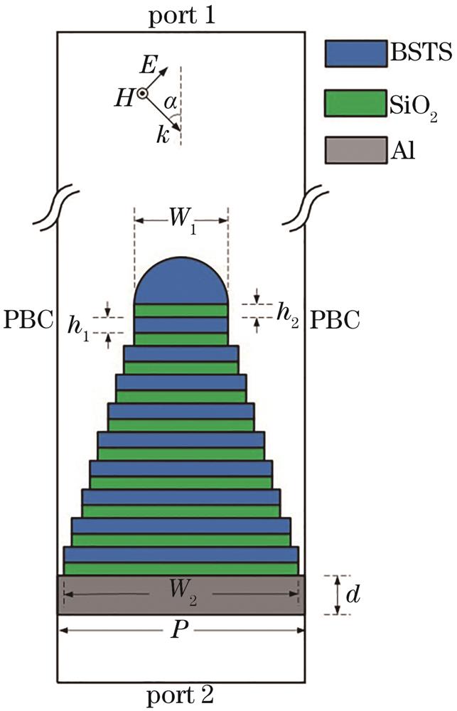
Fig. 1. Schematic diagram of the unit structure of the grating-type ultraviolet absorber based on BSTS material
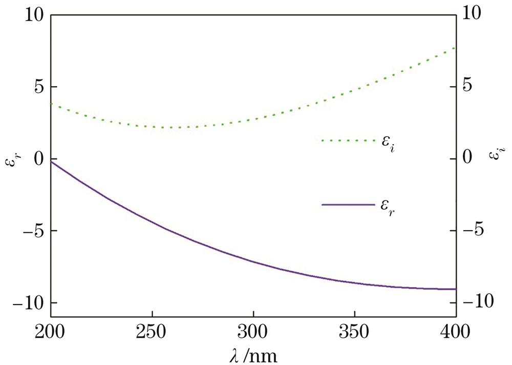
Fig. 2. Relationship between the dielectric constant of the BSTS material and the wavelength
Fig. 3. Relationship between the dielectric constant of the SiO2 material and the wavelength
Fig. 4. Under optimized parameter conditions, contour plot of absorbance as a function of incident angle and wavelength
Fig. 5. Under optimized parameter conditions, relationship between absorptivity, reflectivity and transmittance as a function of wavelength at 60° incidence
Fig. 6. Normalized magnetic field distribution with wavelength of (a) 260 nm, (b) 300 nm and (c) 360 nm in the case of 60° incidence
Fig. 7. In the case of 60° incidence, the absorption rate versus the wavelength when the number of layers of the composite layer L is 6, 10 and 14, respectively, while keeping other optimized parameters unchanged. The embedded graphs are the normalized magnetic field distribution when the wavelength is 350 nm.
Fig. 8. In the case of 60° incidence, the absorption rate versus the wavelength when the BSTS height h1 is 25 nm, 40 nm and 55 nm respectively, while keeping other optimized parameters unchanged. The embedded graphs are the normalized magnetic field distribution when the wavelength is 380 nm.
Fig. 9. In the case of 60° incidence, the absorption rate versus the wavelength when the height of SiO2h2 is 10 nm, 15 nm and 25 nm respectively, while keeping other optimized parameters unchanged. The embedded graphs are the normalized magnetic field distribution when the wavelength is 368 nm.
Fig. 10. In the case of 60° incidence, the absorption rate versus the wavelength when the width W1 is 35 nm, 45 nm and 75 nm respectively, while keeping other optimized parameters unchanged. The embedded graphs are the normalized magnetic field distribution when the wavelength is 280 nm.
Fig. 11. In the case of 60°incidence, the absorption rate versus the wavelength when the width W2 is 80 nm, 90 nm and 100 nm respectively, while keeping other optimized parameters unchanged. The embedded graphs are the normalized magnetic field distribution when the wavelength is 368 nm.
Fig. 12. In the case of 60° incidence, the absorption rate versus the wavelength when the period P is 105 nm, 115 nm and 125 nm respectively, while keeping other optimized parameters unchanged. The embedded graphs are the normalized magnetic field distribution when the wavelength is 394 nm.
|
Table 1. Table of model parameters for dielectric constant of aluminum metals
|
Table 2. Optimized parameters

Set citation alerts for the article
Please enter your email address
© Copyright 2018-2021 | Chinese Laser Press. All Rights Reserved 沪ICP备15018463号-20