
Liming Duan, Cheng Fang, Xueqing Luo, Chuandong Tan, Jinyin Sheng. Direct Generation of Triangular Mesh Finite Element Model From Industrial CT Images[J]. Acta Optica Sinica, 2021, 41(14): 1411002
- Acta Optica Sinica
- Vol. 41, Issue 14, 1411002 (2021)
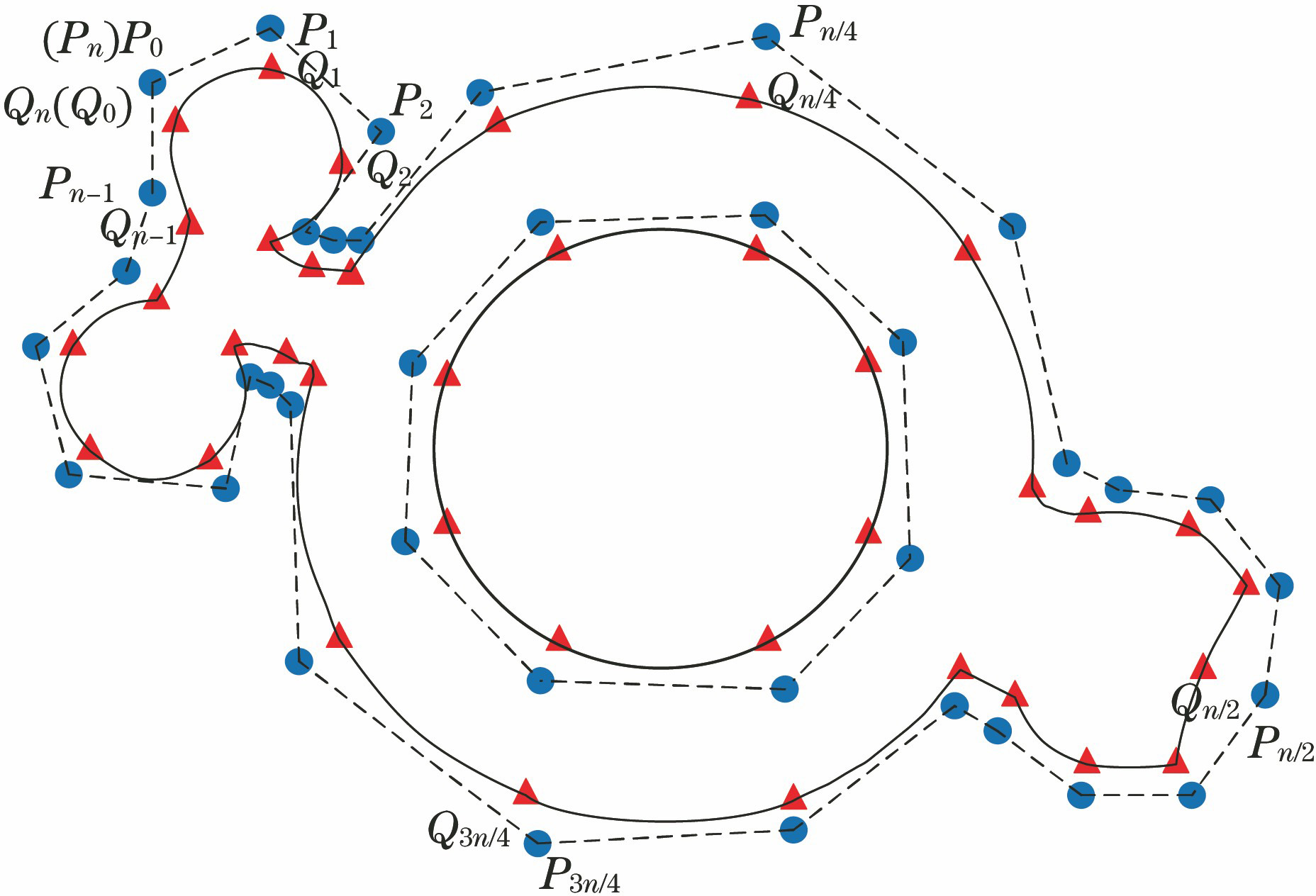
Fig. 1. CT image of the sample
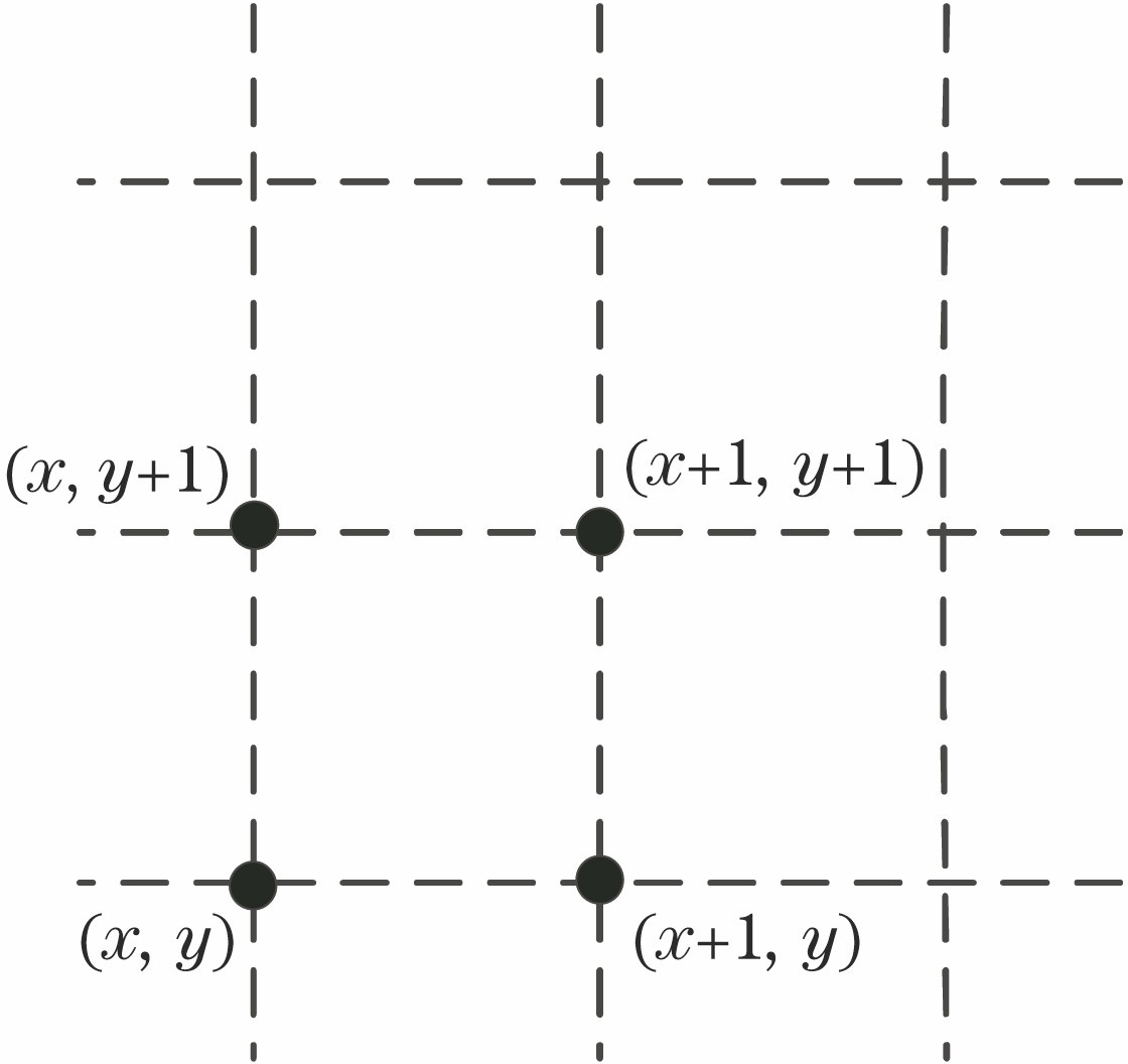
Fig. 2. Boundary of the finite element model of the sample
Fig. 3. Schematic diagram of the unit
Fig. 4. Schematic diagram of CT image unit of the sample
Fig. 5. Schematic diagram of solving the minimizer
Fig. 6. Minimized value of boundary unit
Fig. 7. Triangulation of triangular mesh
Fig. 8. Initial finite element model of the sample
Fig. 9. Value of node normal degree
Fig. 10. Edge flip method
Fig. 11. Unit angle optimization method
Fig. 12. Definition of the twist angle of the triangular mesh
Fig. 13. Finite element model of sample
Fig. 14. Sample stress nephogram
Fig. 15. Industrial CT image sequences of cylinder head
Fig. 16. Finite element models of CT image of cylinder head. (a) Number 33; (b) number 48; (c) number 50; (d) number 57
|
Table 1. Parameter statistics of finite element model of CT image of cylinder head

Set citation alerts for the article
Please enter your email address
© Copyright 2018-2021 | Chinese Laser Press. All Rights Reserved 沪ICP备15018463号-20