
Xinpu Wu, Huaikun Wei, Zhengkun Liu, Keqiang Qiu, Xiangdong Xu, Yilin Hong. Long Trace Profiler for Measuring Groove Density of Diffraction Gratings[J]. Acta Optica Sinica, 2021, 41(6): 0612002
- Acta Optica Sinica
- Vol. 41, Issue 6, 0612002 (2021)
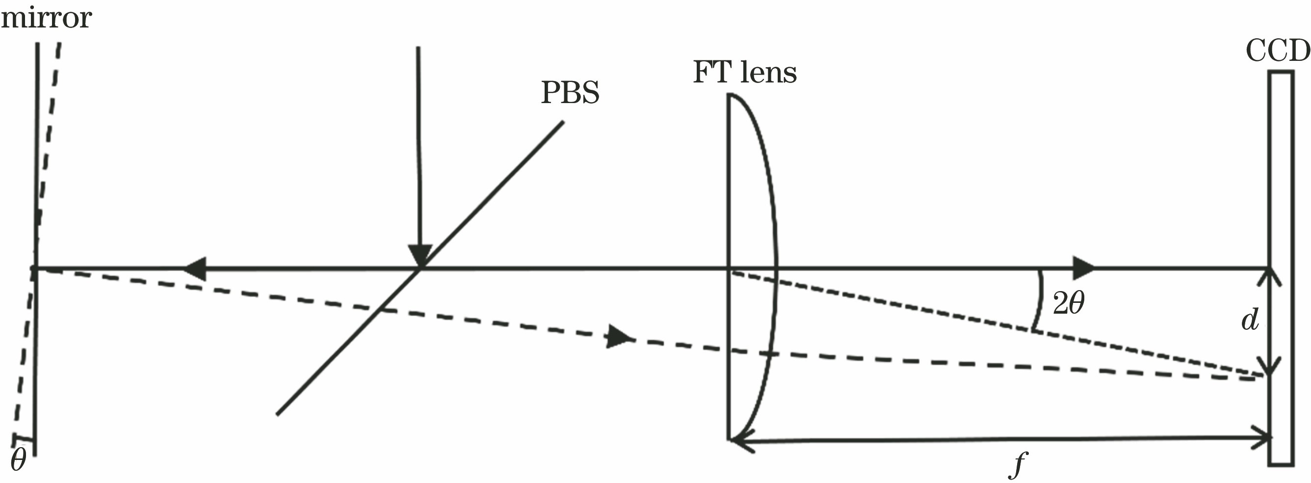
Fig. 1. Measurement schematic of LTP
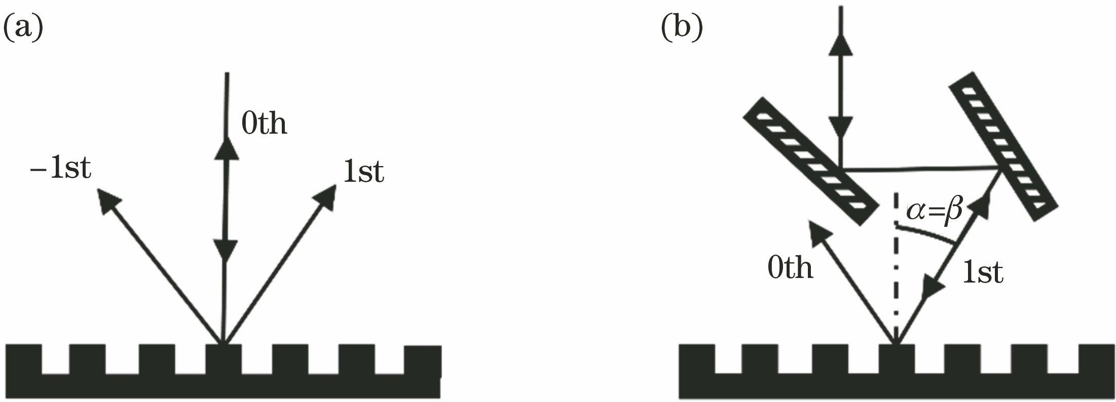
Fig. 2. Principle diagram of LTP detects grating. (a) Grating surface shape measurement with normal incidence; (b) detecting deviation of the grating density at Littrow angle of incidence
Fig. 3. Optical path diagram of LTP system
Fig. 4. Image of LTP system
Fig. 5. Schematic of system error calibration
Fig. 6. Result of system error calibration
Fig. 7. Measurement results of 760 line/mm grating. (a) LTP measurement of the grating in the first diffraction order (m=1)and in the zeroth diffraction order (m=0) (average of 6 groups);(b)(c) reproducibility of LTP measurement on the grating in the first diffraction order(m=1) and in the zeroth diffraction order (m=0) (deviations between each result and the average of 6 groups); (d) uniformity of grating groove density
Fig. 8. Measurement results of 2400 line/mm grating. (a) LTP measurement of the grating in the first diffraction order (m=1) and in the zeroth diffraction order (m=0) (average of 6 groups); (b)(c) reproducibility of LTP measurement on the grating in the first diffraction order (m=1) and in the zeroth diffraction order (m=0) (deviations between each result and the average of 6 groups); (d) uniformity of grating groove density
Fig. 9. Diagrams of 760 line/mm grating diffraction wavefront detected by interferometer. (a) The first diffraction order; (b) the zeroth diffraction order
Fig. 10. Comparison of height profiles for a center line trace on the 760 line/mm grating between LTP and interferometer. (a) The first diffraction order; (b) the zeroth diffraction order; (c) the first diffraction order subtracts the zeroth diffraction order
|
Table 1. Basic parameters of grating

Set citation alerts for the article
Please enter your email address
© Copyright 2018-2021 | Chinese Laser Press. All Rights Reserved 沪ICP备15018463号-20