
Shuo Li, Xiao Feng, Hao Liu, Kai Wang, Yun-Ze Long, S. Ramakrishna. Preparation and application of carbon nanotubes flexible sensors[J]. Journal of Semiconductors, 2019, 40(11): 111606
- Journal of Semiconductors
- Vol. 40, Issue 11, 111606 (2019)
Abstract
1. Introduction
With the development of various industries, including electronic industry, material industry, and medical industry, the quality requirements of electronic products are higher. How to ensure the high flexibility, high energy density, high power density and good stability of electronic products has become a research hotspot in the electronic field. As a new type of electrodes, compared with the traditional electrodes, the flexible sensors (FSs) that are made of flexible materials have the advantages of the good elastic strain, the excellent conductivity and the fantastic durability, which enables FSs to satisfy the requirements mentioned above and lets FSs be widely used in the two-stage matrix converter, the single polyaniline tube, the electrodes in lithium-ion batteries, solar cells and other energy storage components[
As for the materials consisting of FSs, in order to guarantee the good of mechanical flexibility and the good of electrical conduction, materials of FSs mainly include the graphene, the electrospinning, the oxides of transition metal and the conductive polymers[
(1) FCMCs can be used as the electronic transmission channels in FSs because of their excellent electrical conductivity.
(2) FCMCs can be used as the materials of supporting the electrodes in FSs since their excellent properties of bending and folding.
(3) Because of the strong plasticity of the material of carbon element, FCMCs can be easily shaped into various shapes, including the nanostructures of one-dimensional, two-dimensional and three-dimensional, which could have a positive effect on the transmission of current and improve the conductivity of FCMCs.
In summary, the FCMCs play an important role in FSs and become one of the most popular materials which consisting of FSs. In the field of FCMCs, the material of nano-carbon (NC) has become the popular material due to its small size and strong plasticity. According to the forming structure, NC materials are divided into three types[
1.1. Carbon nanofibers
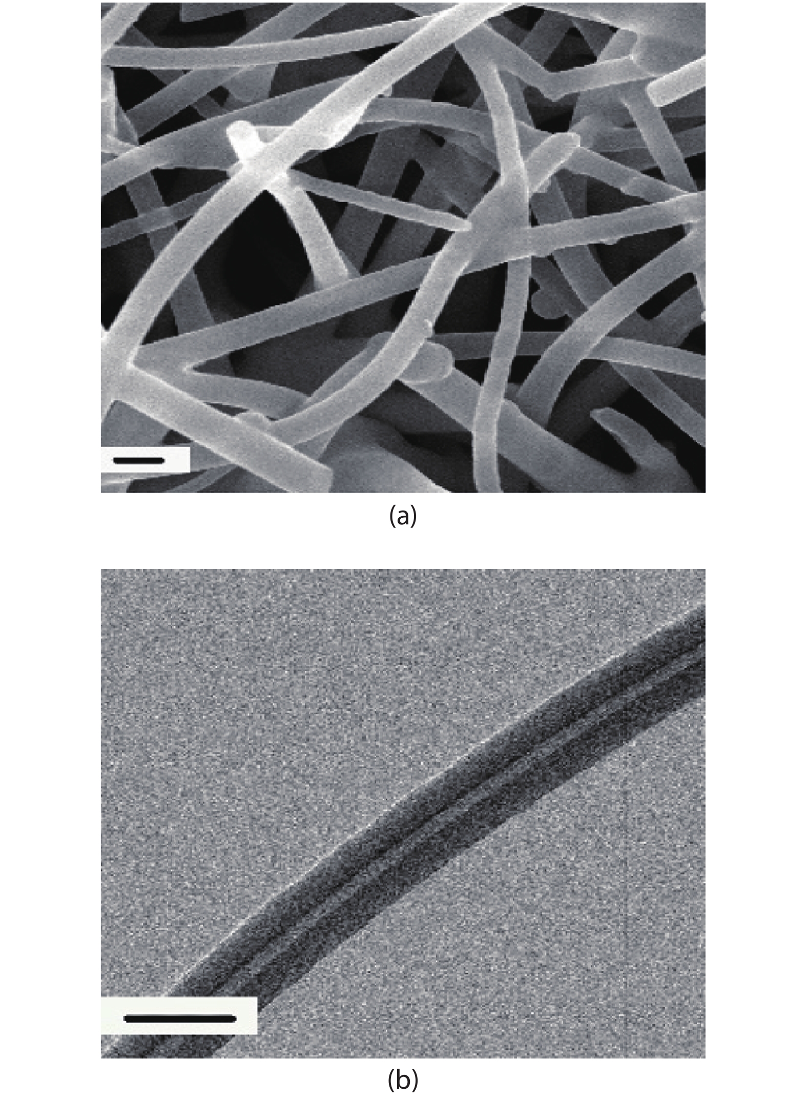
Carbon nanofibers (CNFs) are made of the flaky materials of the polyacrylonitrile fibers, the asphalt fibers, the viscose filaments or the phenolic fibers, which are stacked along the axial direction of the fibers and then carbonized and graphitized. CNFs are a kind of inorganic material made entirely by manual intervention. The structure characterization of the CNFs made by Yang et al. is shown in the Fig. 1[
![]()
Figure 1.Structure characterization of the CNFs. (a) Image of the CNFs under the SEM. (b) Image of the CNFs under the TEM. (Reproduced with permission from Ref. [
The advantages of CNFs include the high strength, the high modulus, the low density, the ultra-high temperature resistance in non-oxidation environment, the low thermal expansion coefficient, the good anisotropy and the good corrosion resistance. The disadvantage of CNFs is the high cost, because the production of carbon nanofibers requires the plenty of the manpower, the raw materials and the time, which restricts the production of the FSs of CNFs[
1.2. Carbon nanospheres
Carbon nanospheres (CNSs) can be obtained by the mixture of carbon raw materials and catalysts, which experience the program of heating at the constant temperature and the program of cooling respectively[
Park et al. fabricated the CNSs by using the porous hollow microcapsules, whose structure is shown as the Fig. 2[
![]()
Figure 2.Structure characterization of the CNSs. (a) Image of the CNSs under the SEM. (b) Image of the CNSs under the TEM. (Reproduced with permission from Ref. [
1.3. Carbon nanotubes
Carbon nanotubes (CNTs) are the hollow tubular carbon materials which are seamless, which are made of graphite sheets of single or multi-layer that curled around the left at a certain angle[
Although CNTs can be used to fabricate FSs, CNTs fabricated from powders cannot be directly used as FSs installed in batteries, and must be attached to a carrier. In theory, materials that can fix the shape of CNTs, such as the material of SiO2, Au and Pd, can be used as the carriers of CNTs[
The polydimethylsiloxane (PDMS) is a kind of the hydrophobic silicone material, which has the color of colorless or pale yellow, the taste of tasteless, the high transparency and the non-toxic. PDMS shows the excellent performance in ductility, heat resistance, cold resistance, hydrophobicity, thermal conductivity, insulation, physiological inertia and chemical stability[
Starting from the structure and properties of the CNTs, this paper introduces in detail the preparation methods and the application fields of the CFS in recent years, expounds the advantages and disadvantages of the preparation methods of the CFS, and shows the application prospects of the CFS in the future.
2. The structure of the CNTs flexible sensor
2.1. The structure and characterization of CNTs
As a kind of the materials of the one-dimensional quantum with special structures, the CNTs are mainly composed of coaxial tubes with several to dozens of layers of carbon atoms arranged in a hexagonal arrangement. The theory model of the CNTs is shown as the Fig. 3.
![]()
Figure 3.Theory model of the CNTs.
About the method of obtaining the CNTs structure characterization, Liao et al. transferred the silver paste/CNTs film on an indium tin oxide (ITO) glass using a single laser shot, which obtained the structure characterization that showed under the scanning electron microscope (SEM) as shown in the Fig. 4[
![]()
Figure 4.Structure characterization of the CNTs. (Reproduced with permission from Ref. [
According to the different orientation of the carbon hexagon along the axis, CNTs can be divided into three types: zigzag, armchair and spiral. The spiral CNTs have the chirality, while the CNTs of zigzag and armchair have no chirality[
According to the number of layers of carbon atoms, CNTs can be divided into the single-walled carbon nanotubes (SWCNTs) and the multi-walled carbon nanotubes (MWCNTs). The SWCNTs are formed by one layer of carbon atoms curling around the left of rotation, which causes the good uniformity and stability since the differences in the size and shape between each carbon atom in SWCNTs are little[
In order to reflect the levels of the rotational energy and the vibrational energy of molecules and reflect dipole moments of chemical molecules inside the CNTs, it is necessary to test the Raman characterization and the UV–vis spectroscopy characterization of the CNTs. In the work of Nguyen et al., under the interference of different materials, the CNTs showed different Raman spectra. And the Raman spectra of pristine (thin solid), I2-intercalated (thick solid), and deintercalated (dashed) SWNTs taken by the 514.5-nm line of Ar-ion laser was shown in Fig. 5[
![]()
Figure 5.Raman spectra of pristine (thin solid), I2-intercalated (thick solid), and deintercalated (dashed) SWNTs in the low Raman shift range taken by: (a) the 514.5-nm line of an Ar-ion laser and by (b) the 647.1-nm line of Kr-ion laser. (Reproduced with permission from Ref. [
In the work of Tsai et al., the UV–vis spectroscopy of the SWCNT with the 9 anthracene carboxylic acid in deionized water (DI water) was shown in Fig. 6[
![]()
Figure 6.(Color online) UV–vis spectroscopy of SWCNT-3 with 9 anthracene carboxylic acid in DI water. (Reproduced with permission from Ref. [
Based on the internal structure, CNTs can be used as the structural materials and the functional materials. As the structural materials, CNTs have high strength because of the covalent bonds between carbon atoms in CNTs. As a functional material, CNTs have good electrical conductivity, thermal conductivity, ductility and other properties, and can be applied in many fields (such as the composite materials and nano-mechanical).
2.2. The structure and function of PDMS
PDMS is an organic material composed of dimethyl siloxane, which has good biocompatibility. The adhesion of PDMS varies little under the changes of temperature, the surface tension of PDMS is small, and the shear resistance of PDMS is very high. Based on these advantages, PDMS is widely used in the fields of the thin film and the physical carrier[
3. Preparation of CNTs flexible sensors
3.1. The hydrothermal auxiliary method
The hydrothermal auxiliary method, which promote the combination between the CNTs and PDMS, could be used for preparing the CFS. Tang et al. provide a method using the hydrothermal assistance for preparing the redox graphene (RG)/PDMS composite flexible sensor, which can be used to fabricate the CFS[
![]()
Figure 7.(Color online) Fabrication steps of the RG/PDMS composite flexible sensor. (Reproduced with permission from Ref. [
The improved preparation method of the CFS is as follows:
(1) The copper mesh is pretreated by the hydrochloric acid/acetone solution to remove various impurities such as oxides adhering to the surface of copper mesh.
(2) The CNTs dispersions are diluted with water.
(3) The copper mesh, whose specification parameters have been shown in Table 1, is placed in a 50 ml autoclave, and then the 35 ml of the CNTs diluted water dispersion is added into the autoclave. After standing for a period of time, CNTs dispersions would deposit on the copper mesh and form a mixture of CNTs and copper mesh (CNTs/Cu).
(4) The solution containing CNTs/Cu in a high-pressure autoclave is put into the oven and heat-treated for 12 h at 180 °C.
(5) Remove the autoclave from the oven and add deionized water into the autoclave. Carefully clean the CNTs/Cu with deionized water in order to eliminate the CNTs powder which do not attach to the copper mesh.
(6) CNTs/Cu cleaned with deionized water is dried in an oven at 50 °C. This step be not completed until all of the water in the autoclave evaporates.
(7) CNTs/Cu removed from the autoclave are divided into two areas: the electrode area and the protected area. The electrode region serves as a connection between CNTs and electrodes, which will not be covered by PDMS because of the good insulation of PDMS. Protected areas protect the CNTs from external interference, which will be covered by PDMS.
(8) The mixed solution of PDMS which is pulled out by dropper was stirred for more than 30 min to achieve the purpose of fully mixing the components in the solution.
(9) The mixed solution of PDMS whose components have been mixed fully is dripped into the protective area of CNTs/Cu. In this step the mixture of CNTs/PDMS/Cu could be obtained.
(10) The CNTs/PDMS/Cu is dried for 2.5 h in a vacuum environment at 120 °C, which ensured that the PDMS monomer is initially polymerized in the protective area of CNTs/PDMS/Cu.
(11) Under the room temperature, the protected region of CNTs/PDMS/Cu has been immersed in the mixed solution of FeCl3/HCl for 12 h. In this solution, the copper mesh can be oxidized to Cu2+ by Fe3+ that exists in FeCl3, which can be dissolved into the solution. The expressions involved are:
In this step, the CNTs/PDMS could be obtained.
(12) CNTs/PDMS obtained by step (11) is carefully cleaned several times with ionic water to remove the remaining etching solution and dry in air.
(13) The CCFS can be obtained by installing an electrode in the electrode region of the CNTs/PDMS.
3.2. The chemical vapor deposition method
The chemical vapor deposition (CVD) is a chemical technology, which forms thin films by chemical reaction on the substrate surface by using gas phase compounds or simple substances containing thin film elements. Jeong et al. provide a method for making the strain sensors by using the CVD technology to mix the graphene foams (GF) and PDMS, which could be used for preparing the CFS[
![]()
Figure 8.Schematic of the process of CVD method of preparing the GF/PDMS strain sensors. (Reproduced with permission from Ref. [
The preparation scheme of CFS improved by this method is as follows:
(1) Using the chemical vapor deposition technology, the CNTs is adhered to the foam nickel template.
(2) Etching the nickel foam template with hot solution of HCl.
(3) The CNTs is immersed in a small bottle containing isopropanol solution, and is broken for 20 min by an edd y current mixer, which causes that the flake of CNTs is dispersed in isopropanol.
(4) Stewing the mixed solution of CNTs/isopropanol for 24 h to make the plate-like CNTs precipitate.
(5) Using the micropipette to inlay CNTs/isopropanol onto glass sheets which are arranged in a rectangular (3 × 20 mm2) pattern with polyimide tape to rearrange CNTs. Because the cost of making electrode pattern with polyimide tape is low, the electrodes with various shapes and sizes can be conveniently designed[
(6) Put the glass sheet containing the CNTs/isopropanol in the oven with a temperature of 50 °C to evaporate the isopropanol and take out the glass sheet from the oven after finishing evaporating the isopropanol.
(7) Polyimide tape is removed from glass slide and PDMS is poured onto glass slide. After curing and peeling, a composite strain sensor film of CNTs/PDMS is prepared.
The comparison between two methods is shown in Table 3.
As shown in the preparation process of two methods and the Table 3, compared with the CFS prepared by the CVD method, the CFS prepared by the hydrothermal auxiliary method has several advantages, which are shown as follow:
(1) short preparation time,
(2) materials that be got easily (such as the solution of hydrochloric acid/acetone and the solution of FeCl3/HCl), which could reduce the cost and the difficulty of preparation.
The disadvantage of the hydrothermal auxiliary method is the need for more experimental steps, which leads to more details to pay attention to.
4. Application fields of CNTs composite flexible sensors
CFS have been used in various fields for the excellent stability, ductility and conductivity. At present, there are two application forms of carbon nanotube flexible sensors:
(1) Other materials are added into the CFS to form the CNTs composite flexible sensor (CCFS).
(2) A new system is composed of CFS or CCFS and other devices.
Both of these two methods could improve the conductivity and electrochemical performance of CFS, and expand the application field of CFS, including the fields of electronics, micromechanical, and thermal management.
4.1. Application in the field of electronics
A flexible symmetric supercapacitor based on TiO2 and CNTs was invented, and a hybrid electrode design was introduced in the work of Chien et al.[
![]()
Figure 9.(Color online) (a) Respective cyclic voltammograms of TiO2 nanotube supercapacitor, PEDOT–MWNT film supercapacitor and TiO2 nanotube + PEDOT–MWNT film supercapacitor in 1 M H2SO4 aqueous electrolyte. (b) Nyquist plots of TiO2 nanotube supercapacitor, PEDOT–MWNT film supercapacitor, and TiO2 nanotube + PEDOT–MWNT film supercapacitor from high frequency to low frequency. (Reproduced with permission from Ref. [
High-speed DC circuit breaker played a very important role in the circuit, and the optimization of the contact material of high-speed DC circuit breaker became the cornerstone of the reliable function of high-speed DC circuit breaker. Among many materials, pure metal materials had high affinity for welding. The Ag/CdO materials did not meet the requirements of European Union. The SnO2, ZnO and the graphite, which worked normally at low current, had not been optimized for high current applications (such as the railway industry). Based on the situation, a kind of material of Ag/CNTs was designed in the work of Jaüimoviül et al.[
![]()
Figure 10.(Color online) Temperature dependence of resistivity of several materials. (Reproduced with permission from Ref. [
Chang et al. demonstrated the superior performance of thin film transistors with a functionalized SWCNTs-blended poly (3-hexylthiophene) (F-SWCNT-P3HT) channel and multiwalled CNTs source and drain electrodes[
![]()
Figure 11.(Color online) (a) The values of contact resistance. (b) Characteristics of drain current versus gate voltage of transistors with a P3HT or F-SWCNT-P3HT channel and gold or MWCNT S/Ds. (Reproduced with permission from Ref. [
On the structure of digitized gold electrode, for the detection of CO, NH3, CO2 and other gases, the gas sensor of sulfonated CNTs (s-CNTs) and the mixture gas sensor of CNTs/polyaniline (PANI) were prepared respectively[
![]()
Figure 12.(Color online) Resistance evolution of resulting structures as a function of gas concentrations. (a) CO. (b) CO2. (c) NH3. (Reproduced with permission from Ref. [
Carbon nanotube flexible sensors could also detect chemical gases. Based on the flexible carbon nanotube sensor and using the non-equilibrium Green's function, a kind of tunnel type carbon nanotube field effect transistor (CNTFET) which could be used to detect the toxic gas in the tunnel was designed, which was shown in Fig. 13[
![]()
Figure 13.(Color online) Two-dimensional circuit model for ballistic CNTFET. (Reproduced with permission from Ref. [
![]()
Figure 14.(Color online) Drain-source current diagram versus dielectric constant. (Reproduced with permission from Ref. [
![]()
Figure 15.(Color online) Transport features. (a) Sulfur Dioxide. (b) Acetonitrile. (c) Sarin Gas. (d) Carbonyl Chloride at logarithmic scale for
4.2. Application in the micromechanical system
Sha et al. invented electroplated Ni-CNT nanocomposites for micromechanical resonator applications[
![]()
Figure 16.(Color online) (a) and (c) Reflection losses of raw CNTs and Ni with 2−5 mm thickness. (b) and (d) Complex permittivity
4.3. Application in the electron field
Wu et al. provided the idea of applying CNTs to the emission devices in the cold cathode electron field and described the cathode ray tubes[
A MEMS/NEMS electron impact gas ion generator based on the CNTs, which had an integrated extractor gate for portable mass spectrometry, was constructed in the work of Hu et al.[
4.4. Application in the back-end interconnection
Liang et al. introduced the method of combining electrical measurement with atomic pair circuit simulation, studied the conductivity of doped SWCNTs and doped MWCNTs, and provided a feasible choice for the next generation of back-end interconnection[
4.5. Application in the thermal management
Because of the thermodynamic properties, CNTs materials were also widely used in the field of thermal management applications. In the process of thermal management applications, it was necessary to estimate the thermal properties of CNTs. For the estimation of the thermal properties of CNTs, CNTs were arranged vertically on the mounted Pt/Si micro-hot plate in the work of Silvestri et al., and then the thermal properties of CNTs were estimated directly[
4.6. Application in the medicine and the anthroponomy
Jung et al. prepared a kind of the dry ECG electrode of the CNTs/PDMS composite, which could be easily connected to the traditional ECG equipment, and showed the long-term wearable monitoring ability and the robustness to exercise[
Rezaei et al. provided an application of the mixed electrodes of MWCNTs/modified carbon quantum dots/pencil graphite in the field of electrochemical determination of dextromethorphan (DXM)[
Xie et al. pointed out a kind of CNTs water dispersion which was used in the thermal effect of microwave[
CNTs/PDMS composite film which is the part of CCFS could also be used in single monitoring of human body. Yang et al. provided a kind of flexible Ag/CNTs/PDMS composite membrane sensor[
5. Conclusion
In this paper, the preparation methods of the CFS are proposed, and several cases of the application of CFS and CCFS which containing CNTs and other materials in recent years are described, which could prove that either CFS or CCFS has a wide use in various fields, such as the energy storage systems, the artificial skin and the nanocomposites. However, there are several remaining challenges in the application fields of the CFS. That the CFS is improved on the basis of the existing technology in order to be used as the elastic electromyogram (EMG) sensor could control the muscle activity in the human body easily. Being used as the material support for the flexible electronic devices with flexibility, the CFS could promote the development of the wearable devices. In addition, based on the good ductility and electric conductivity, CFS could be used as the carrier devices for the human-computer interactive motion monitoring, which could promote the development of automatic control.
Acknowledgments
This work was supported by the Qingdao Postdoctoral Fund and Key Research (No. 2015118), the Development Plan of Shandong Province (No. 2017GGX50114 and No. 2018GGX105007) and the Scientific Research Development Plan of Shandong Higher Education Institutions (No. J18KA316), National Natural Science Foundation of China (No. 60123456).
References
[1] K Wang, L W Li, Y Lan et al. Application research of chaotic carrier frequency modulation technology in two-stage matrix converter. Math Probl Eng, 2019, 1(2019).
[2] K Wang, S Z Zhou, Y T Zhou et al. Synthesis of porous carbon by activation method and its electrochemical performance. Int J Electrochem Sci, 13, 10766(2018).
[3] Y Z Long, L J Zhang, Z J Chen et al. Electronic transport in single polyaniline and polypyrrole microtubes. Phys Rev B, 71, 165412(2005).
[4] K Wang, L W Li, X Wen et al. Electrodeposition synthesis of PANI/MnO2/graphene composite materials and its electrochemical performance. Int J Electrochem Sci, 12, 8306(2017).
[5] K Wang, J B Pang, L W Li et al. Synthesis of hydrophobic carbon nanotubes/reduced graphene oxide composite films by flash light irradiation. Front Chem Sci Eng, 12, 376(2018).
[6] H J Qiu, W Z Song, X X Wang et al. A Calibration-free self-powered sensor for vital sign monitoring and finger tap communication based on wearable triboelectric nanogenerator. Nano Energy, 58, 536(2019).
[7] X X Wang, W Z Song, M H You et al. Bionic single electrode electronic skin unit based on piezoelectric nanogenerator. ACS Nano, 12, 8588(2018).
[8] C J Chien, S S Deora, P C Chang et al. Flexible symmetric supercapacitors based on TiO2 and carbon nanotubes. IEEE Trans Nanotechnol, 10, 706(2011).
[9] H Chen, A R Iyer, R G Harley et al. Dynamic grid power routing using controllable network transformers (CNTs) with decoupled closed-loop controller. IEEE Trans Ind Appl, 51, 2361(2015).
[10] M Tabib-Azar, Y Xie. Sensitive NH3OH and HCl gas sensors using self-aligned and self-welded multiwalled carbon nanotubes. IEEE Sens J, 7, 1435(2007).
[11] M Shahshahan, P Keinänen, J Vuorinen. The effect of ultrasonic dispersion on the surface chemistry of carbon nanotubes in the Jeffamine D-230 polyetheramine medium. IEEE Trans Nanotechnol, 16, 741(2017).
[12] J Cheon, S Choi, Y J Heo et al. Fabrication of n-type CNT field-effect transistor using energy band engineering layer between CNT and electrode. IEEE Electron Device Lett, 34, 1436(2013).
[13] Y Z Long, M M Li, W M Sui et al. Electrical, dielectric and surface wetting properties of multi-walled carbon nanotubes/nylon-6 nanocomposites. Chin Phys B, 18, 1221(2009).
[14] Z Zhang, J G Delgado-Frias. Carbon nanotube SRAM design with metallic CNT or removed metallic CNT tolerant approaches. IEEE Trans Nanotechnol, 11, 788(2012).
[15] J Zheng, B Sun, Y Z Lonf et al. Fabrication of nanofibers by low-voltage near-field electrospinning. Adv Mater Res, 486, 60(2012).
[16] Z T Yang, J Xu, J Q Wang et al. Design and preparation of self-driven BSA surface imprinted tubular carbon nanofibers and their specific adsorption performance. Chem Eng J, 373, 923(2019).
[17] A Gyulassy, A Knoll, K C Lau et al. Interstitial and interlayer ion diffusion geometry extraction in graphitic nanosphere battery materials. IEEE Trans Visual Comput Graph, 22, 916(2016).
[18] G W Park, J B Yoo, G J Kim. Fabrication of spherical CNT skeins formed by self-entangled fibers from hollow type mesoporous silica microcapsules. J Ind Eng Chem, 76, 457(2019).
[19] R A Dubin, i G Callegari, J Kohn et al. Carbon nanotube fibers are compatible with mammalian cells and neurons. IEEE Trans NanoBiosci, 7, 11(2008).
[20] Y C Lee, M H Li, Y T Cheng et al. Electroplated Ni-CNT nanocomposite for micromechanical resonator applications. IEEE Electron Device Lett, 33, 872(2012).
[21] H Li, E J Jr Evans, C B Mullins et al. Ethanol decomposition on Pd-Au alloy catalysts. J Phys Chem C, 122, 22024(2018).
[22] H Li, G Henkelman. Dehydrogenation selectivity of ethanol on close-packed transition metal surfaces: a computational study of monometallic, Pd/Au, and Rh/Au catalysts. J Phys Chem C, 121, 27504(2017).
[23] H Li, K Shin, G Henkelman. Effects of ensembles, ligand, and strain on adsorbate binding to alloy surfaces. J Chem Phys, 149, 1(2018).
[24] H Li, L Luo, P Kunal et al. Oxygen reduction reaction on classically immiscible bimetallics: a case study of RhAu. J Phys Chem C, 122, 2712(2018).
[25] Y H Hwang, D Seo, M Roy et al. Capillary flow in PDMS cylindrical microfluidic channel using 3-D printed mold. J Microelectromechan Syst, 25, 238(2016).
[26] H H Guo, L Lou, X D Chen et al. PDMS-coated piezoresistive NEMS diaphragm for chloroform vapor detection. IEEE Electron Device Lett, 33, 1078(2012).
[27] D Ryu, N Castaño. Multivariate characterization of light emission from ZnS: Cu-PDMS self-sensing composites under cyclic tensile strains. IEEE Sens Lett, 2, 1(2018).
[28] Y B Zhu, B Yang, J Q Liu et al. An integrated flexible harvester coupled triboelectric and piezoelectric mechanisms using PDMS/MWCNT and PVDF. J Microelectromechan Syst, 24, 513(2015).
[29] H Y Liao, J R Ho, S K Chang-Jian. Fabrication of carbon nanotube field-emission cathodes by laser-induced transfer of carbon nanotubes and silver paste. J Display Technol, 10, 1083(2014).
[30] A R Binesh, R Kamali. Effects of chirality on single-file water permeability and diffusivity through single wall carbon nanotubes. Micro Nano Lett, 12, 109(2017).
[31] Q R Zhang, Y Han, L C Wu. Influence of electrostatic field on the adsorption of phenol on single-walled carbon nanotubes: A study by molecular dynamics simulation. Chem Eng J, 363, 278(2019).
[32] R M Chen, J Liang, J Lee et al. Variability study of MWCNT local interconnects considering defects and contact resistances—Part I: pristine MWCNT. IEEE Trans Electron Devices, 65, 4955(2018).
[33] V M Nguyen, g I Yang, Y Jung et al. Resonance raman study of I2-intercalated single-walled carbon nanotubes. IEEE Trans Nanotechnol, 6, 126(2007).
[34] T J Tsai, P C Wang. Preparation and characterization of aqueous dispersions based on single-walled carbon nanotubes functionalized with carboxyl anthracenes. The 12th International Microsystems, Packaging, Assembly and Circuits Technology Conference, 299(2017).
[35] Y C Tang, Z B Zhao, H Hu et al. Highly stretchable and ultrasensitive strain sensor based on reduced graphene oxide microtubes-elastomer composite. ACS Appl Mater Interfaces, 7, 27432(2015).
[36] Y R Jeong, H Park, S W Jin et al. Highly stretchable and sensitive strain sensors using fragmentized graphene foam. Adv Funct Mater, 25, 4228(2015).
[37] J Jacimovic, L Felberbaum. Electro-mechanical properties and welding characteristics of Ag/MoS2, Ag/WS2, Ag/CNTs and Ag/CdO materials for high-DC current contact applications. The 27th International Conference on Electrical Contacts, 132(2014).
[38] C H Chang, C H Chien. Functionalized single-walled carbon-nanotube-blended P3HT-based thin-film transistors with multiwalled carbon-nanotube source and drain electrodes. IEEE Electron Device Lett, 32, 1457(2011).
[39] E Ilarion, S I Spiridon, B F Monea. Comparative study of gas sensing microsensors based on sulfonated CNTs and CNTs/polyaniline mixture. International Conference and Exposition on Electrical and Power Engineering, 65(2016).
[40] M Ghodrati, i A Farmani, A Mir. Nanoscale sensor-based tunneling carbon nanotube transistor for toxic gases detection: a first-principle study. IEEE Sens J, 19, 7373(2019).
[41] L N Sha, P Gao, T T Wu et al. Chemical Ni-C bonding in Ni-carbon nanotube composite by a microwave welding method and its induced high-frequency radar frequency electromagnetic wave absorption. ACS Appl Mater Interfaces, 9, 40412(2017).
[42] L C Wu, Y Han, Q R Zhang et al. Effect of external electric field on nanobubbles at the surface of hydrophobic particles during air flotation. RSC Adv, 9, 1792(2019).
[43] C F Hu, C M Lin, W Fang. Integration of Pdms-infiltrated CNTs and Si bulk-micromachining for monolithic physical sensors application. The 17th International Conference on Solid-State Sensors, Actuators and Microsystems, 1565(2013).
[44] J Liang, R M Chen, R Ramos et al. Investigation of Pt-salt-doped-standalone-multiwall carbon nanotubes for on-chip interconnect applications. IEEE Trans Electron Devices, 66, 2346(2019).
[45] C Silvestri, P Picciafoco, B Morana et al. Electro-thermal simulation and characterization of vertically aligned CNTs directly grown on a suspended microhotplate for thermal management applications. IEEE Sens, 2014, 827(2014).
[46] H C Jung, J H Moon, D H Baek et al. CNT/PDMS composite flexible dry electrodes for long-term ECG monitoring. IEEE Trans Biomed Eng, 59, 1472(2012).
[47] B Rezaei, N Irannejad, A A Ensafi et al. Application of modified carbon quantum dots/multiwall carbon nanotubes/pencil graphite electrode for electrochemical determination of dextromethorphan. IEEE Sens J, 16, 2219(2016).
[48] S X Xie, F Q Gao, S C Patel et al. Clinically relevant CNT dispersions with exceptionally high dielectric properties for microwave theranostic applications. IEEE Trans Biomed Eng, 61, 2718(2014).
[49] Y P Yang, C Z Luo, J J Jia et al. A wrinkled Ag/CNTs-PDMS composite film for a high-performance flexible sensor and its applications in human-body single monitoring. Nanamaterials, 9, 1(2019).


Set citation alerts for the article
Please enter your email address

© Copyright 2018-2021 | Chinese Laser Press. All Rights Reserved 沪ICP备15018463号-20