
Xiao-Yuan LIU, Bao-Dan LIU, Ya-Nan JIANG, Ke WANG, Yang ZHOU, Bing YANG, Xing-Lai ZHANG, Xin JIANG, [in Chinese], [in Chinese], [in Chinese], [in Chinese], [in Chinese], [in Chinese], [in Chinese], [in Chinese]. In-situ Synthesis of Perovskite SrTiO3 Nanostructures with Modified Morphology and Tunable Optical Absorption Property[J]. Journal of Inorganic Materials, 2019, 34(1): 65
- Journal of Inorganic Materials
- Vol. 34, Issue 1, 65 (2019)
Abstract
Over the past few decades, perovskite materials owning a featured ABX3 molecular formula and fascinating functional properties have received global research interest and have been widely investigated. Extensive efforts have been paid to improve the performances of these existed ABX3 materials and to seek new members in perovskite family[
As one of the most popular and versatile materials in perovskite family[
From the point of crystallography, SrTiO3 shows a simple cubic (s.c.) crystallographic structure and a space group Pm-3m, implying a minimum surface energy in (001) plane. For this reason, the crystallographic morphology of SrTiO3 is favorable to form cube-like structure. However, the functional properties of SrTiO3 nanostructures such as catalytic reactions are strongly dependent on its crystal facet. Considering all these points, an approach that can realize the in-situ growth of SrTiO3 nanostructures for strong substrate adherence, the crystal facet tailoring for selective catalytic reaction and superior crystal quality is generally needed for further promoting their applications in diverse fields.
As a conventional surface treatment method for enhancing metal wear resistance, plasma electrolytic oxidation (PEO) technology owns many unique advantages. It has been regarded as an ideal method to prepare metallurgical bonded film with strong adherence for cyclic utilization in some harsh environment. Furthermore, the porous PEO film can provide sufficient nucleation sites for the further in-situ growth of SrTiO3 nanostructures. In this paper, a two-step method by combining traditional PEO and hydrothermal method to in-situ synthesize SrTiO3 nanostructures on metal substrate was developed based on our previous work[
1 Experimental
1.1 PEO film fabrication
The PEO treatment was applied to preparation of porous TiO2 film in accordance with the experiment routes of our previous work[
1.2 In-situ synthesis of SrTiO3 nanostructures
In this step, porous PEO film containing Sr source was used as the nucleation site of SrTiO3 nanostructures. The film was vertically immersed into 15 mL NaOH solution (0.5 mol/L, 1 mol/L, 1.5 mol/L) in a Teflon-lined autoclave and heated at 180℃ for different hydrothermal durations (1 h, 2 h, 4 h, 6 h, 8 h).
1.3 Characterizations of SrTiO3 nanostructures
The phases and crystal structures of SrTiO3 samples were characterized by X-ray diffraction (XRD, Rigaku D/max 2400). 3D spatial profiles of PEO film was measured via a 3D X-ray microscope (Xradia Versa XRM 500). X-ray photoelectron spectroscopy (XPS, Thermal VG/ESCALAB250) was used to obtain the binding energy of SrTiO3 samples. The morphology and composition of SrTiO3 nanostructures were characterized by a field-emission scanning electron microscopy (FE-SEM, FEI Inspect F50) equipped with a Quanta 600 Energy Dispersed X-ray spectrometer (EDS) system. The microstructure and crystallinity of SrTiO3 nanostructures were analyzed using a 200 kV transmission electron microscopy (TEM, Tecnai G2 F20). UV-Vis diffuse reflectance spectra (DRS) of SrTiO3 nanostructures were obtained on a HITACHI U-3900 spectrophotometer.
2 Results and discussions
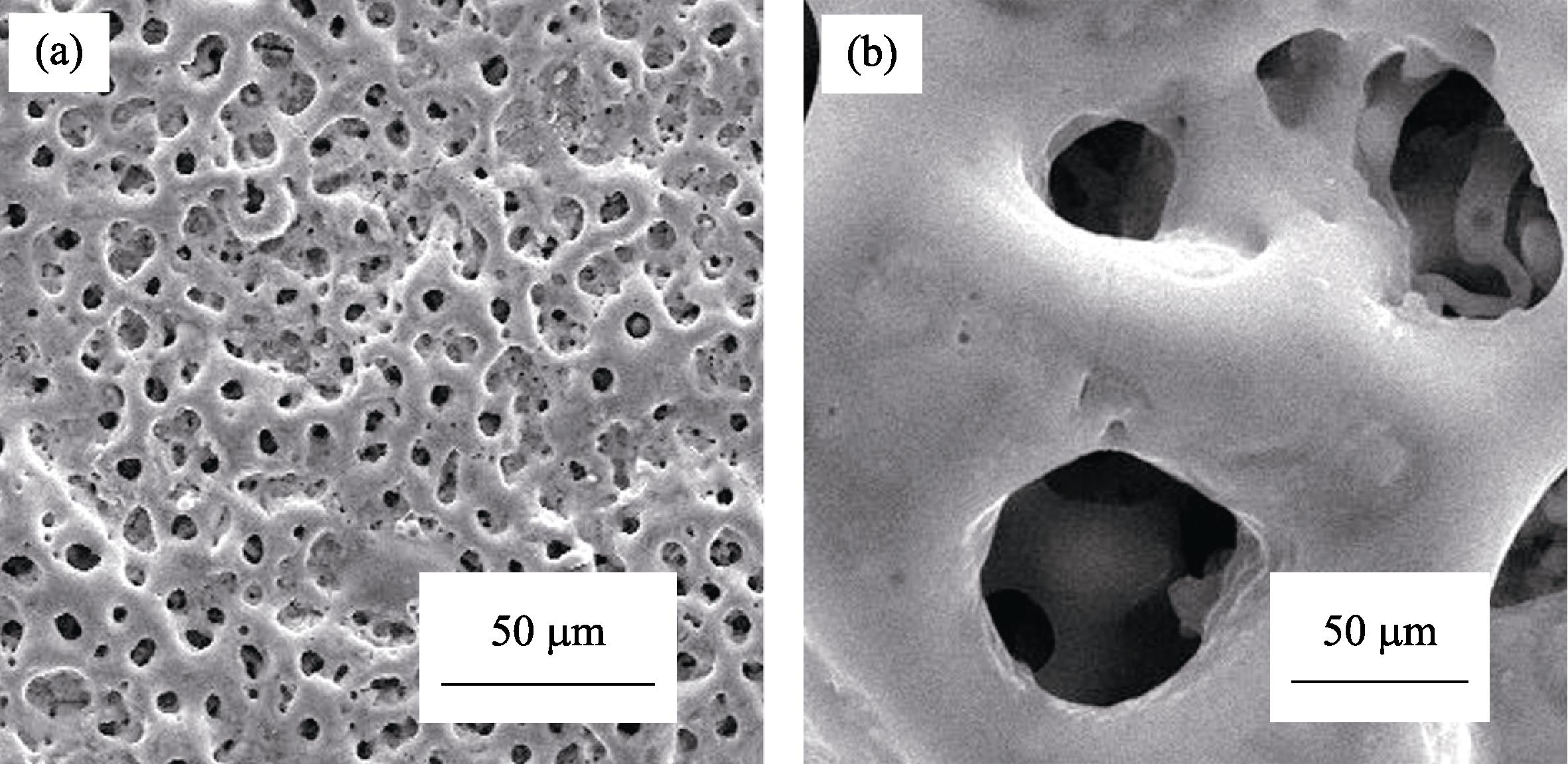
Previous work has demonstrated the merits of PEO method in obtaining metal oxide nanostructures with strong substrate adherence[
XRD measurement was carried out to investigate the structure/phase information of all PEO samples before (Fig. S3) and after (Fig. 1) hydrothermal treatment. The (110) (101) and (111) peaks of TiO2 in rutile phase (JCPDS no. 21-1276; a=b=0.495 nm, c=0.296 nm) at 2θ=27.4°, 36.1° and 41.2° can be clearly distinguished. In addition, a slight trace of (101) peak at 2θ=25.3° can also be detected, which originates from anatase phase TiO2 (JCPDS no. 21-1272; a=b=0.379 nm, c=0.951 nm). The coexistence of these two TiO2 phases in the PEO film coincides with the results of other groups[
![]()
Figure 1.XRD patterns of SrTiO3 samples prepared under different hydrothermal conditions
Hydrothermal treatment is applied on PEO film for the in-situ growth of SrTiO3 nanocrystal. Fig. 2 shows the typical morphology of SrTiO3 nanocrystals in-situ nucleated on HSCE PEO film after hydrothermal treatment. It can be seen that the surface of the PEO film is fully covered with numerous cube-like nucleus with regular crystalline facets. Each micro-cube shows smooth surface and sharp edges, and the typical size of these microcubes is 1 µm -3 µm. In addition, it is also found that NaOH solution plays a key role in the formation of SrTiO3 nanostructures. The addition of NaOH in hydrothermal reaction will promote the high density of nucleation and accelerate the growth rate of SrTiO3 nanocrystals (Fig. S4)[
![]()
Figure 2.(a,c) SEM image and TEM bright field image of SrTiO3 microcubes; (b) Crystallographic model of cube-like SrTiO3 nanostructure; (d,e) HRTEM image and FFT pattern of SrTiO3 microcubes
When the Sr content in initial electrolyte was reduced, the SrTiO3 nanocrystals show quite different morphology as compared to SrTiO3 microcubes. In SEM images (Fig. 3(a)) widespread ultra-thin nanosheets take the place of SrTiO3 microcubes and fully cover the PEO film. Fig. S8 gives the SEM image of PEO sample treated in 1 mol/L NaOH for different durations. It can be seen that the size of nanosheets varies among 100 nm-200 nm as the reaction time is 0.5 h (Fig. S8(a)), and then grows to micron scale as the time extends to 1 h (Fig. S8(b)) and 2 h (Fig. S8(c)). Further increasing the treating time causes the edge curling and assembling of sheet structure (Fig. S8(d)-(e)), which is probably induced by the stress release. Adjusting the NaOH concentration also leads to the size evolution and morphology changing of nanosheets. Taking Fig. S8, Fig. S9 and Fig. S10 as comparisons, the sheet size shows an increasing tendency in pace with the increase of NaOH concentration. Through the HRTEM image (Fig. 3(d)) and corresponding FFT pattern (Fig. 3(e)), we can calculate the interlayer spacing of such nanosheet to be 0.371 nm along (001) plane and 0.278 nm along (110) plane of SrTiO3.
![]()
Figure 3.(a,c) SEM image and TEM bright field image of Sr1-
The exposed facet is calculated to be (11¯0) crystalline plane. Additionally, it can be seen that the crystalline quality of nanosheet is not so good as microcube (Fig. 2(d)). EDS data (Table S2) shows that the Sr/Ti ratio of SrTiO3 nanosheets is about 0.21, which is much smaller than the stoichiometric ratio of standard SrTiO3. In order to get more convincing conclusion, XPS element component analysis is used to collect the signals of the topmost surface of SrTiO3 nanosheets. The Sr/Ti ratio of nanosheet is found to be around 0.31 (Table S3), which is similar to the EDS result. Thus these nanosheets can be regarded more accurately as Sr1-δTiO3. The XPS result (Fig. 4) of Sr exhibits two peaks at around 133.7 eV and 135.4 eV which correspond to the 3d5/2 and 3d3/2 electron orbit of Sr2+. Two peaks of Ti2p located at 458.0 eV (2p3/2) and 463.8 eV (2p1/2) are observed, which belong to Ti4+ in SrTiO3[
![]()
Figure 4.XPS spectra of (a) Sr3d, (b) Ti2p and (c) O1s of Sr1-
Based on all the results above, the tentative formation mechanism of SrTiO3 microcubes and nanosheets isproposed (Fig. 5). The PEO film serves as both substrate and precursor for the nucleation of SrTiO3 nanocrystals and the Sr/Ti source for hydrothermal reaction. During hydrothermal process, Sr/Ti species in the PEO film can quickly dissolve under elevated temperature in alkaline environment, then the released Sr2+ and Ti4+ species suffer from a hydrolysis process. The hydrolysis of Ti4+ is very quick[
![]()
Figure 5.Schematic diagram describing the formation process of SrTiO3 microcubes and Sr1-
The optical properties of SrTiO3 microcube and Sr1-δTiO3 nanosheets were roughly examined through a UV-Vis spectrometer. Fig. 6 shows the UV-Vis absorption spectra of PEO film and SrTiO3 samples synthesized under different conditions. It can be seen that the SrTiO3 microcube has only strong absorption around 390 nm with smaller inclination, while the Sr1-δTiO3 nanosheets show two absorption edges at around 335 nm and 400 nm, respectively. Apparently, the 390 nm absorption is directly from SrTiO3 microcube, which corresponds to a band gap of 3.18 eV. For Sr1-δTiO3 nanosheets, the absorption edge located at around 335 nm, which corresponds to a band gap of 3.71 eV, exhibits obvious blue-shift in comparison with the bulk SrTiO3 (3.25 eV) due to size effect[
![]()
Figure 6.SEM images of SrTiO3 microcubes obtained on PEO film under HSCE and in 1.0 mol/L NaOH with different durations (a) 180℃, 0.5 h; (b) 180℃, 1 h; (c) 180℃, 2 h; (d) 180℃, 8 h
3 Conclusions
SrTiO3 microcubes and Sr1-δTiO3 nanosheets have been in-situ fabricated on PEO film through a combined technology. The SrTiO3 microcubes obtained under HSCE show a regular cubic structure with (001) exposed crystal facets and superior crystalline quality without defects. Reducing the concentration of Sr source induces an obvious morphology evolution from microcubes to Sr1-δTiO3 nanosheets with a thickness of about several nanometers and (110) exposed facet. In addition, the two types of SrTiO3 nanostructures show significant difference in composition and optical absorption properties. SrTiO3 microcubes own a higher Sr concentration and a bulk-like optical absorption behavior, while Sr1-δTiO3 nanosheets with insufficient Sr content exhibit obvious blue-shift in optical absorption due to the size effect. It is believed that the initial Sr/Ti atomic ratio in PEO film is mainly responsible for the morphology evolution of SrTiO3 nanostructures. This feasible in-situ synthetic strategy to SrTiO3 nanostructures with modified morphology, tunable band gap and optical properties will pave a solid way toward their promising application in the fields of photocatalysis for clean energy and environmental processing.
Supporting information
In-situ Synthesis of Perovskite SrTiO3 Nanostructures with Modified Morphology and Tunable Optical Absorption Property
LIU Xiao-Yuan1,2, LIU Bao-Dan1, JIANG Ya-Nan1, WANG Ke1,2, ZHOU Yang1,2, YANG Bing1, ZHANG Xing-Lai1, JIANG Xin1
(1. Shenyang National Laboratory for Materials Science, Institute of Metal Research, Chinese Academy of Sciences, Shenyang 110016, China; 2. School of Materials Science and Engineering, University of Science and Technology of China, Hefei 230026, China)
![]()
Figure 7.SEM images of SrTiO3 microcubes obtained on PEO film under HSCE and in 1.5 mol/L NaOH with different durations (a) 180℃, 4 h; (b) 180℃, 6 h; (c) 180℃, 8 h
![]()
Figure 8.SEM images of Sr1-
![]()
Figure 9.SEM images of Sr1-
![]()
Figure 10.SEM images of Sr1-
References
[1] M GRATZEL, S KAZIM, K NAZEERUDDIN M et al. Perovskite as light harvester: a game changer in photovoltaics. Angew Chem. Int. Edit., 53, 2812-2824(2014).
[2] T SATO, U SULAEMAN, S YIN. Solvothermal synthesis and photocatalytic properties of chromium-doped SrTiO3 nanoparticles. Appl Catal B. -Environ., 105, 206-210(2011).
[3] K IWASHINA, A KUDO. Rh-doped SrTiO3 photocatalyst electrode showing cathodic photocurrent for water splitting under visible- light irradiation.. Am. Chem. Soc., 133, 13272-13275(2011).
[4] B COMES R, C KASPAR T, Y SMOLIN S et al. 106(9): 092901-1-5(2015).
[5] Y LIU, I PARK K, S XU et al. Piezoelectric BaTiO3 thin film nanogenerator on plastic substrates. Nano Letters, 10, 4939-4943(2010).
[6] E GRABOWSKA. Selected perovskite oxides: characterization, preparation and photocatalytic properties—a review. Applied Catalysis B: Environmental, 186, 97-126(2016).
[7] A ASHOK, B MADHAVAN. Review on nanoperovskites: materials, synthesis, and applications for proton and oxide ion conductivity. Ionics, 21, 1-10(2014).
[8] A KUDO, Y MISEKI. Heterogeneous photocatalyst materials for water splitting. Chemical Society Reviews, 38, 253-278(2009).
[9] G CHEN S, Y DIAMANT, O MELAMED et al. Core-shell nanoporous electrode for dye sensitized solar cells: the effect of the SrTiO3 shell on the electronic properties of the TiO2 core. J. Phys. Chem. B, 107, 1977-1981(2003).
[10] S BURNSIDE, J KRUEGER, F LENZMANN et al. Surface photovoltage spectroscopy of dye-sensitized solar cells with TiO2, Nb2O5, and SrTiO3 nanocrystalline photoanodes: indication for electron injection from higher excited dye states. J. Phys. Chem. B, 105, 6347-6352(2001).
[11] Q KANG, P LI, T WANG et al. Photocatalytic reduction of carbon dioxide by hydrous hydrazine over Au-Cu alloy nanoparticles supported on SrTiO/TiO coaxial nanotube arrays. Angewandte Chemie International Edition, 54, 841-845(2014).
[12] T CAO, Y LI, C WANG et al. A facile in situ hydrothermal method to SrTiO3/TiO2 nanofiber heterostructures with high photocatalytic activity. Langmuir, 27, 2946-2952(2011).
[13] Z LONG, Q QIU X, H WEI X. Preparation of SrTiO3 cubes by molten salt method and its surface ions modification with Cu(II) clusters. J. Inorg. Mater., 28, 1103-1107(2013).
[14] G TANG Y, H YAN J, R ZHU Y et al. Preparation and photocatalytic hydrogen generation activity of nitrogen doped SrTiO3 under visible light irradiation.. Inorg. Mater., 23, 443-448(2008).
[15] L JI, D MCDANIEL M, S WANG et al. A silicon-based photocathode for water reduction with an epitaxial SrTiO3 protection layer and a nanostructured catalyst. Nat. Nano, 10, 84-90(2014).
[16] H YAN J, L ZHANG, R ZHU Y et al. Preparation and photocatalytic hydrogen production of NiO(CoO)/N-SrTiO3 heterojunction complex catalyst under simulated sunlight irradiation. J. Inorg. Mater., 24, 666-670(2009).
[17] V KOVALEVSKY A, S POPULOH. PATRÍCIO S G, et al. Design of SrTiO3-based thermoelectrics by tungsten substitution. The Journal of Physical Chemistry C, 119, 4466-4478(2015).
[18] Y HWANG H, A OHTOMO. A high-mobility electron gas at the LaAlO3/SrTiO3 heterointerface. Nature, 427, 423-426(2004).
[19] Q KUANG, S YANG. Template synthesis of single-crystal-like porous SrTiO3 nanocube assemblies and their enhanced photocatalytic hydrogen evolution. ACS Applied Materials & Interfaces, 5, 3683-3690(2013).
[20] G CHEN Z, H ZHAN, J ZHUANG et al. Correlation between multiple growth stages and photocatalysis of SrTiO3 nanocrystals. The Journal of Physical Chemistry C, 119, 3530-3537(2015).
[21] T BASKARAN, A SIVANANTHAM, G SREEDHAR et al. A role of lithiated sarcosine TFSI on the formation of single crystalline SrTiO3 nanocubes via hydrothermal method. Materials Letters, 133, 127-131(2014).
[22] K CHENG, L DONG, Q LUO et al. 4: 5084-1-5(2014).
[23] Y JIANG, B LIU, Z ZHAI et al. A general strategy toward the rational synthesis of metal tungstate nanostructures using plasma electrolytic oxidation method. Appl. Surf. Sci., 356, 273-281(2015).
[24] N JIANG Y, D LIU B, J YANG W et al. New strategy for the in situ synthesis of single-crystalline MnWO4/TiO2 photocatalysts for efficient and cyclic photodegradation of organic pollutants. CrystEngComm., 18, 1832-1841(2016).
[25] Y JIANG, B LIU, L YANG et al. 5: 14330-1-10(2015).
[26] Y JIANG, B LIU, W YANG et al. Crystalline (Ni1-xCox)5TiO7 nanostructures grown in situ on a flexible metal substrate used towards efficient CO oxidation. Nanoscale, 9, 11713-11719(2017).
[27] X JIANG, S WYBORNOV, L ZHANG et al. Highly efficient nanoarchitectured Ni5TiO7 catalyst for biomass gasification. ACS Applied Materials & Interfaces, 4, 4062-4066(2012).
[28] N BARATI, F GOLESTANIFARD, A YEROKHIN et al. Alumina- zirconia coatings produced by plasma electrolytic oxidation on Al alloy for corrosion resistance improvement.. Alloy Compd., 724, 435-442(2017).
[29] E BRECKENFELD, T HAASCH R, W MARTIN L. Single crystal perovskites analyzed using X-ray photoelectron spectroscopy: 1. SrTiO3(001). Surface Science Spectra, 21, 87-94(2014).
[30] M GIERSIG, H MOCKEL, F WILLIG. Formation of uniform size anatase nanocrystals from bis(ammoniumlactato)titanium dihydroxide by thermohydrolysis. Journal of Materials Chemistry, 9, 3051-3056(1999).
[31] F DANG, K KATO, I MIMURA K et al. Nano-sized cube-shaped single crystalline oxides and their potentials, composition, assembly and functions. Advanced Powder Technology, 25, 1401-1414(2014).
[32] K FUJINAMI, J KAMIYA, K KATAGIRI et al. Sub-10 nm strontium titanate nanocubes highly dispersed in non-polar organic solvents. Nanoscale, 2, 2080-2083(2010).
[33] Y GUO, G LIU, Z REN et al. Single crystalline brookite titanium dioxide nanorod arrays rooted on ceramic monoliths: a hybrid nanocatalyst support with ultra-high surface area and thermal stability. CrystEngComm., 15, 8345-8352(2013).
[34] A AKKERMAN Q, G MOTTI S. KANDADA A R S, et al. Solution synthesis approach to colloidal cesium lead halide perovskite nanoplatelets with monolayer-level thickness control.. Am. Chem. Soc., 138, 1010-1016(2016).
[35] D DIMITRAKOPOULOS C, B MITZI D, T XU Z et al. Semiconducting perovskites (2-XC6H4C2H4NH3)2SnI4 (X = F, Cl, Br): steric interaction between the organic and inorganic layers. Inorganic Chemistry, 42, 2031-2039(2003).


Set citation alerts for the article
Please enter your email address

© Copyright 2018-2021 | Chinese Laser Press. All Rights Reserved 沪ICP备15018463号-20