
Lei Chen, Zelin Liu, Chuan Guo, Tongcheng Yu, Minsun Chen, Zhongjie Xu, Hao Liu, Guomin Zhao, Kai Han. Nanosecond laser-induced controllable periodical surface structures on silicon[J]. Chinese Optics Letters, 2022, 20(1): 013802
- Chinese Optics Letters
- Vol. 20, Issue 1, 013802 (2022)
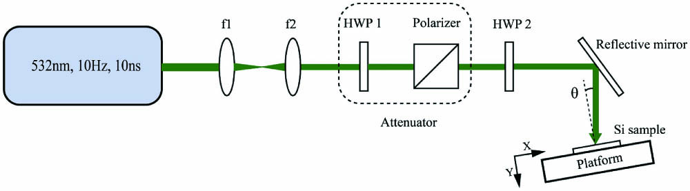
Fig. 1. Schematic diagram of the experimental setup.
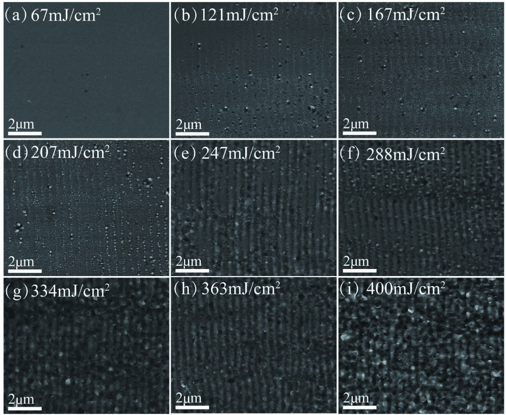
Fig. 2. SEM images of LIPSS with irradiation fluence ranging from 67 mJ/cm2 to 400 mJ/cm2 with the pulse number of 600.
Fig. 3. AFM images of LIPSSs with irradiation fluence of 247 mJ/cm2 and 363 mJ/cm2 under pulse number of 600. (A), (a) 2D AFM image, (B), (b) horizontal height of LIPSS along the green line, and (C), (c) 3D AFM image.
Fig. 4. 2D-FFT and 1D-FFT spectrograms of LIPSS SEM images with different fluence: (a), (c) 247 mJ/cm2 and (b), (d) 288 mJ/cm2.
Fig. 5. SEM images of LIPSS with irradiation pulse number ranging from 400 to 900 under fluence of 247 mJ/cm2.
Fig. 6. SEM images of LIPSSs at different incident angles: (a) 20°, (b) 30°, (c) 45°, and (d) 60°. (e) Angular dependence of LIPSS periodicities. Red, blue, and black lines represent, respectively, theoretical values of Λ(p), Λ(s), and fitting of experimental data. Dots represent experimental data of 45° polarization.
Fig. 7. SEM images of LIPSS after irradiation with different polarization angles: 0°, 30°, 60°, and 90° under fluence of 207 mJ/cm2 and pulse number of 800. The red arrow indicates the laser polarization direction.
Fig. 8. 2D-FFT spectrograms of LIPSS in Fig. 7 .
Fig. 9. Reflectance spectrum of untreated Si and that with two different LIPSSs.
Fig. 10. General formation of LIPSS at different laser fluence and pulse number with different kinds of surface morphology.

Set citation alerts for the article
Please enter your email address
© Copyright 2018-2021 | Chinese Laser Press. All Rights Reserved 沪ICP备15018463号-20