• Chinese Optics Letters
  • Vol. 20, Issue 1, 013802 (2022)
Lei Chen1, Zelin Liu1, Chuan Guo1、2、*, Tongcheng Yu1、2, Minsun Chen1、2, Zhongjie Xu1、2, Hao Liu1、2, Guomin Zhao1、2, and Kai Han1、3、**
Author Affiliations
  • 1College of Advanced Interdisciplinary Studies, National University of Defense Technology, Changsha 410073, China
  • 2Hunan Provincial Key Laboratory of High Energy Laser Technology, Changsha 410073, China
  • 3State Key Laboratory of Pulsed Power Laser Technology, Hefei 230037, China
  • show less
    DOI: 10.3788/COL202220.013802 Cite this Article Set citation alerts
    Lei Chen, Zelin Liu, Chuan Guo, Tongcheng Yu, Minsun Chen, Zhongjie Xu, Hao Liu, Guomin Zhao, Kai Han. Nanosecond laser-induced controllable periodical surface structures on silicon[J]. Chinese Optics Letters, 2022, 20(1): 013802 Copy Citation Text show less

    Abstract

    In this paper, an effective method is proposed to generate specific periodical surface structures. A 532 nm linearly polarized laser is used to irradiate the silicon with pulse duration of 10 ns and repetition frequency of 10 Hz. Laser-induced periodic surface structures (LIPSSs) are observed when the fluence is 121 mJ/cm2 and the number of pulses is 1000. The threshold of fluence for generating LIPSS gradually increases with the decrease of the number of pulses. In addition, the laser incident angle has a notable effect on the period of LIPSS, which varies from 430 nm to 1578 nm, as the incident angle ranges from 10° to 60° correspondingly. Besides, the reflectivity is reduced significantly on silicon with LIPSS.

    1. Introduction

    Since Birnbaum[1] first, to the best of our knowledge, obtained laser-induced periodic surface structures (LIPSSs) by utilizing a pulsed ruby laser to irradiate a semiconductor in 1965, LIPSS has been widely used in many fields, such as controlling structural colors[2,3], producing hydrophobic and hydrophilic surfaces[4,5], reducing bacterial adhesion and forming biofilms[6], enhancing friction properties[7], optical waveguide[8,9], and optical information storage[10]. For various materials including metals[11], dielectrics[12,13], semiconductors[14], and recently researched 2D materials[15], LIPSS can be formed by irradiating the surface of the materials with a linearly polarized laser of appropriate fluence[16]. People have shown extensive interest in the formation mechanism and process of LIPSS, especially on the silicon (Si) surface. Si being a key material in electronics and optical communications, strategies for turning Si into a material that allows light emission are of great interest[17]. Besides, porous Si has been identified as a suitable candidate to provide efficient luminescence due to the presence of crystalline Si nanostructures. Furthermore, light-emitting Si devices could result in a new generation of Si chips and extend the functionality of Si technology from microelectronics into optoelectronics eventually[18]. However, the band gap of crystalline Si is 1.11 eV, which makes it difficult to absorb a laser with wavelengths greater than 1100 nm, and it has a relatively high reflectivity for visible to near-infrared (NIR) light. These deficiencies restrict the development of crystalline Si. Laser-induced micro-nano structures can effectively reduce the reflectivity of Si, thereby enhancing the absorption of the laser.

    In recent years, most of the works on LIPSS have adopted femtosecond and picosecond laser pulses[19,20]. A femtosecond laser was used to produce LIPSS on metal and semiconductor samples with different structural colors, and it was found that LIPSS has a greater impact on the reflective properties of the material[21]. The papers of nanosecond pulsed lasers to produce LIPSS are relatively rare compared to that of femtosecond and picosecond lasers[22]. In fact, nanosecond lasers can reduce costs of equipment and provide higher single pulse energy[23]. Nanosecond lasers were used to generate LIPSSs perpendicular to the laser polarization on semiconductors such as InP, GaAs, GaP, and SiC[24]. LIPSS in SiO2 substrates covered with a three-layer compound was investigated using a single nanosecond NIR laser pulse[25], and it was proved that the LIPSS period depended on the laser parameters such as pulse energy, pulse duration, and the characteristics of the material layer; the LIPSS can be manipulated by changing these influencing factors simultaneously.

    Many parameters such as laser wavelength, pulse duration, fluence, polarization, pulse number, incident angle, and refractive index of environmental media could affect the period size or surface morphology of LIPSS. Nuernberger et al.[26] found that when the incident angle increased from 0° to 70°, the period of LIPSS increased from 520 nm to 4.4 µm for a p-polarized laser and from 520 nm to 1.2 µm for an s-polarized laser on stainless steel. Gemini et al.[14] investigated LIPSS formed by a femtosecond laser on the surface of Si and SiC and found that the period increased from an average value of approximately 600 nm for a high number of pulses (N>50) to a value of approximately 760 nm for a small number of pulses (N<25). In this Letter, we demonstrated the general formation of LIPSSs on the Si surface produced by nanosecond laser pulses with different fluences and pulse numbers. Meanwhile, we analyzed the angular dependence of LIPSS periodicity. Besides, we found the antireflection effect on Si with LIPSS.

    2. Experimental Setup

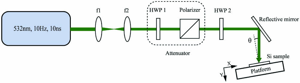
    A diagram of the experimental setup is illustrated in Fig. 1, where a Nd:Y3Al5O12 (Nd:YAG) nanosecond laser amplifier was employed as an irradiation source to deliver polarized pulse trains at the repetition rate of 10 Hz, with central wavelength of 532 nm and pulse duration of 10 ns. The maximum single pulse energy delivered by the laser system is 46 mJ. The f1 and f2 are lenses to collimate the beam to 3.7mm. Half-wave plates (HWP1 and HWP2) are used to adjust the polarization of the laser. HWP1 and the polarizer were combined into an attenuator to control the energy. HWP2 was employed to change the light polarization from the horizontal to vertical direction. The number of shots was controlled by the laser controller. The laser was incident at 10° on the Si sample to prevent the oscillator from being damaged by the reflected light. A circular Si disk of 99.99% purity with a 50 mm diameter and 1 mm thickness was used as a target material, which was fixed on a 2D displacement platform. After the laser irradiation, the sample surface was analyzed by scanning electron microscopy (SEM, Hitachi S-4800) and atomic force microscopy (AFM, NT-MDT prima).

    Schematic diagram of the experimental setup.

    Figure 1.Schematic diagram of the experimental setup.

    3. Results and Discussion

    Figure 2 shows the SEM images of LIPSS with irradiation fluence ranging from 121mJ/cm2 to 400mJ/cm2 with the pulse number of 600. There is no modification when the fluence is 67mJ/cm2. It can be seen from Figs. 2(b)2(d) that when the fluence is lower than 207mJ/cm2 the morphology of the LIPSS appears to be a fractured ripple, and it seems that only a very shallow layer is attached to the Si surface; at the same time, the LIPSS ripples are composed of many tiny nanoparticles. These images reveal that the ridges of the ripples are quasi-periodically populated by nanosized (100 nm or even smaller diameter) craters, which basically grow on the ridges, not on the valleys. The sharp edges that surround the crater holes indicate the possible occurrence of incubation effects triggered by rapid local heat accumulation, which would lead to a micro-explosion. It is well known that sharp edges would enhance field effects; if that is the case, there is a possibility of freeing electrons to seed rapid avalanche ionization[27]. Figures 2(e)2(h) show that when the fluence of the laser varies from 207mJ/cm2 to 363mJ/cm2, the LIPSS is continuous, and the depth of ripple is obviously deeper than that of Figs. 2(b)2(d). Figure 2(i) shows that when the fluence is increased to 400mJ/cm2 the LIPSS comes to be slightly melted, and the periodicity becomes less regular.

    SEM images of LIPSS with irradiation fluence ranging from 67 mJ/cm2 to 400 mJ/cm2 with the pulse number of 600.

    Figure 2.SEM images of LIPSS with irradiation fluence ranging from 67 mJ/cm2 to 400 mJ/cm2 with the pulse number of 600.

    As for the formation of nanoparticles, ablation may be the main reason, as far as we know. Ablation may occur through several different mechanisms, such as phase explosion, evaporation, spallation, and fragmentation[21]. The plume of the ablated material is composed of nanoparticles and other substances. Some of the nanoparticles generated in ablation are deposited back onto the sample. Meanwhile, the laser energy transfer from the air plasma induced by ablation to the sample and enhanced re-deposition of hot nanoparticles back onto the sample are due to the presence of high pressure from the ambient gas plasma[28].

    Figure 3 shows the AFM images of two typical LIPSSs with irradiation fluence of 247mJ/cm2 and 363mJ/cm2 under pulse number of 600. Figures 3(A) and 3(a) show the 2D AFM images of the two LIPSSs, which are in good agreement with the SEM images in Figs. 2(e) and 2(h). Figures 3(B) and 3(b) show the height information of the LIPSS in the horizontal direction. It can be seen that the depth of LIPSS is 4–7 nm at fluence of 247mJ/cm2, and the depth of LIPSS is 30–50 nm at fluence of 363mJ/cm2, which demonstrates that the depth of LIPSS increases with the laser fluence. Figures 3(C) and 3(c) are the three-dimensional AFM images of the two LIPSSs, which indicate that the height of the surface protrusion is, respectively, 27 nm (247mJ/cm2) and 63 nm (363mJ/cm2).

    AFM images of LIPSSs with irradiation fluence of 247 mJ/cm2 and 363 mJ/cm2 under pulse number of 600. (A), (a) 2D AFM image, (B), (b) horizontal height of LIPSS along the green line, and (C), (c) 3D AFM image.

    Figure 3.AFM images of LIPSSs with irradiation fluence of 247 mJ/cm2 and 363 mJ/cm2 under pulse number of 600. (A), (a) 2D AFM image, (B), (b) horizontal height of LIPSS along the green line, and (C), (c) 3D AFM image.

    The 2D fast Fourier transform (FFT) and one-dimensional (1D) FFT spectrograms of the SEM images are used to calculate the period of the LIPSS, as shown in Fig. 4. The irradiation fluences are 247mJ/cm2 and 288mJ/cm2 at the pulse number of 600, respectively. Figures 4(a) and 4(b) are the 2D-FFT spectrograms, in which a group of symmetrical frequency points representing the spatial frequency of LIPSS can be seen. Figures 4(c) and 4(d) are the 1D-FFT spectrograms along the transverse direction, in which the position of the peak represents the spatial frequency of LIPSS. The results of 2D-FFT are consistent with the 1D-FFT spectrograms. As for the LIPSS with irradiation fluence of 247mJ/cm2, the period is 435 nm; and for LIPSS with irradiation fluence of 288mJ/cm2, the period is 421 nm. The periods of other LIPSSs are either 435 nm or 421 nm, owing to the resolution of the FFT method, and the periods are not correlated to the fluence. Therefore, we consider the period ΛLIPSS421–435 nm. The parametric decay model[14,29] was used to explain the phenomenon that when the fluence was relatively high, the period remained constant with respect to the fluence in general.

    2D-FFT and 1D-FFT spectrograms of LIPSS SEM images with different fluence: (a), (c) 247 mJ/cm2 and (b), (d) 288 mJ/cm2.

    Figure 4.2D-FFT and 1D-FFT spectrograms of LIPSS SEM images with different fluence: (a), (c) 247 mJ/cm2 and (b), (d) 288 mJ/cm2.

    The pulse number applied to the Si surface is another significant parameter that affects the morphology of LIPSS. Figure 5 shows the SEM images of LIPSS with irradiation pulse numbers ranging from 400 to 900 under laser fluence of 247mJ/cm2. It can be seen that the LIPSS with 400 pulses is very shallow, indicating that this is the initial status of LIPSS formation, and only a small amount of energy is periodically modulated on the Si surface. When it comes to 500 pulses, the LIPSS appears to be fractured, which is composed of many tiny nanoparticles. When the number of pulses is further increased from 600 to 900, the ripples become much more continuous and regular, and, at 900 pulses, larger nanoparticles are attached to the surface of LIPSS, which are different from the tiny nanoparticles at 500 pulses. The influence of the pulse number on the morphology of LIPSS can be explained by a feedback mechanism. The first few pulses generate a rough surface, which facilitates the coupling of energy for the following laser pulses. Specific spatial frequencies of the roughness distribution can better absorb radiation. During repetitive exposure, via this positive feedback, certain spatial periods are favored to form the grating-like LIPSS pattern. It was believed that interpulse effects affect the morphological characteristics of LIPSS[20], which include ablation[30], hydrodynamical melt flows[31], alterations of the material structure at the surface between crystalline or amorphous states[32], and chemical reactions with the ambient environment[3335].

    SEM images of LIPSS with irradiation pulse number ranging from 400 to 900 under fluence of 247 mJ/cm2.

    Figure 5.SEM images of LIPSS with irradiation pulse number ranging from 400 to 900 under fluence of 247 mJ/cm2.

    The incident angle of the laser is the essential parameter to control the period of LIPSS. Based on the theory of interference between the incident laser and surface plasmon polaritons (SPPs), the periodicities dependence of LIPSS on the incident angle of p- and s-polarized light is theoretically predicted by Bauerle[36] and Bonch-Bruevich[37]: Λ(p)=λRe[η]sinθ,Λ(s)=λ(Re[η]2sin2θ)12,with θ being the incident angle, and Re[η] being the real part of the effective refractive index of the observed air-Si interface, which reads asRe[η]=Re[εair·εSiεair+εSi],with εair and εSi being the dielectric constant of air and Si. At λ=532nm, Re[η] results as 0.972 for Si[38]. In Eq. (1), the ‘±’ represents SPPs that can propagate in the forward (+ sign) or backward (− sign) direction depending on how light is incident upon the target. It has been demonstrated that the backward propagating situation dominates[39], so we only consider the ‘−’ situation when it comes to the theoretical Λ(p), as seen in Fig. 6. In this study, the pulsed laser applied to the Si surface is polarized 45°; thus, the values of the LIPSS period are predicted to be between theoretical Λ(p) and Λ(s): Λ(s)<Λ(π/4)<Λ(p).

    Figure 6 shows the SEM images of LIPSSs at four different incident angles and the fitting of experimentally obtained periodicities. The periods of LIPSSs at four incident angles are 601 nm, 789 nm, 1147 nm, and 1578 nm, as obtained by 1D-FFT and 2D-FFT. In addition, the period of LIPSS at an incident angle of 10° is about 435 nm. Increasing incident angles is accompanied by growing periodicities. The experiment data is in good agreement with the prediction on the whole.

    SEM images of LIPSSs at different incident angles: (a) 20°, (b) 30°, (c) 45°, and (d) 60°. (e) Angular dependence of LIPSS periodicities. Red, blue, and black lines represent, respectively, theoretical values of Λ(p), Λ(s), and fitting of experimental data. Dots represent experimental data of 45° polarization.

    Figure 6.SEM images of LIPSSs at different incident angles: (a) 20°, (b) 30°, (c) 45°, and (d) 60°. (e) Angular dependence of LIPSS periodicities. Red, blue, and black lines represent, respectively, theoretical values of Λ(p), Λ(s), and fitting of experimental data. Dots represent experimental data of 45° polarization.

    SEM images of LIPSS after irradiation with different polarization angles: 0°, 30°, 60°, and 90° under fluence of 207 mJ/cm2 and pulse number of 800. The red arrow indicates the laser polarization direction.

    Figure 7.SEM images of LIPSS after irradiation with different polarization angles: 0°, 30°, 60°, and 90° under fluence of 207 mJ/cm2 and pulse number of 800. The red arrow indicates the laser polarization direction.

    In this work, HWP2 is used to control the polarization angle of the laser. Respectively, the SEM images of LIPSSs after irradiation with different polarization angles of 0°, 30°, 60°, and 90° under laser fluence of 207mJ/cm2 and pulse number of 800 are shown in Figs. 7(a)7(d). Figure 8 shows the 2D-FFT spectrograms of the SEM images at different polarization angles. Figures 7 and 8 show that the orientation of the LIPSS obtained in this work is strictly perpendicular to the polarization direction of the incident laser. The polarization dependence of LIPSS was explained as follows: due to the effective coupling of the incident electromagnetic radiation with the plasmon oscillation, a significant enhancement of the field in the vicinity of the structure can be produced, explaining the polarization dependence of LIPSS[40].

    2D-FFT spectrograms of LIPSS in Fig. 7.

    Figure 8.2D-FFT spectrograms of LIPSS in Fig. 7.

    After generating LIPSSs on Si, the reflectance spectrum of Si with different morphologies is measured by a spectrophotometer (Hitachi, U-4100). The result is presented in Fig. 9. LIPSS1 is produced with fluence of 167mJ/cm2 and pulse number of 600, as illustrated in Fig. 2(h). LIPSS2 is produced with fluence of 363mJ/cm2 and pulse number of 600, as shown in Fig. 2(c). It can be seen from Fig. 9 that LIPSS can reduce the reflectivity of Si, and LIPSSs with different morphologies have different reduction effects. For example, the reflectivities of Si with no treatment, LIPSS1, and LIPSS2 are 37.7%, 29.6%, and 15.7% at the wavelength of 532 nm, respectively. Compared to untreated Si, the reflectivities of Si with LIPSS1 and LIPSS2 have reduced by 21.5% and 58.4%, respectively.

    Reflectance spectrum of untreated Si and that with two different LIPSSs.

    Figure 9.Reflectance spectrum of untreated Si and that with two different LIPSSs.

    Based on the above discussion of the formation of LIPSS on Si with a nanosecond laser, the relationship between the LIPSS and the laser parameters is shown in Fig. 10. Appropriate fluence and pulse number should be applied to generate LIPSS, because if either of them is too high or too low, it will cause a disappearance of LIPSS. The laser fluence applied to the Si target surface ranges from 67mJ/cm2 to 400mJ/cm2, and the pulse number ranges from 100 to 1200. The white area in the table indicates that there is no obvious damage on the Si surface, and no LIPSS is formed; the yellow area indicates that discontinuous and shallow LIPSS is formed on the Si surface; the red area indicates the formation of continuous and clearer LIPSS on the Si surface; the green area indicates the formation of quasi-periodic nanoparticles on the Si surface; the blue area indicates that the Si surface is severely ablated, and no LIPSS is observed. It can be seen from the table that when the laser fluence and pulse number are both small, there will be no obvious modification on the Si surface; on the contrary, it will cause severe ablation. Only when the two parameters are in the middle, LIPSS with different morphologies and nanoparticles can be generated. At the same time, it is noted that when the fluence is lower than 67mJ/cm2, LIPSS is not observed, indicating that the lowest laser fluence to generate LIPSS on Si is about 67mJ/cm2 for the 532 nm nanosecond laser. For other fluence conditions, only a suitable number of pulses can be applied to generate a continuous and regular LIPSS.

    General formation of LIPSS at different laser fluence and pulse number with different kinds of surface morphology.

    Figure 10.General formation of LIPSS at different laser fluence and pulse number with different kinds of surface morphology.

    4. Conclusion

    In this work, LIPSS was generated on a Si surface by a 532 nm laser with pulse duration of 10 ns with different fluence, pulse number, and incident angle. General formation of LIPSS with different morphology is observed when laser fluence ranges from 121mJ/cm2 to 400mJ/cm2 and pulse number ranges from 300 to 1000. It is found that in the case of low fluence and low pulse number, LIPSS ripples are usually discontinuous, shallow, and composed of some tiny nanoparticles. In the case of high fluence and high pulse number, LIPSS ripples usually appear to be continuous and deep, with some larger nanoparticles attached to them. The period of LIPSS is around 430 nm when the laser is incident at a small angle of about 10°, and it is irrelevant to the fluence and pulse number. Besides, the angular dependence of LIPSS periodicity is demonstrated, and the period increases from 430 nm to 1578 nm when the incident angle ranges from 10° to 60° correspondingly. The LIPSS orientation is perpendicular to the laser polarization. Lastly, the reflectance spectra of Si with and without LIPSS are measured. It is found that LIPSS has a good antireflection effect on Si.

    References

    [1] M. Birnbaum. Semiconductor surface damage produced by ruby lasers. J. Appl. Phys., 36, 3688(1965).

    [2] H. Lochbihler. Colored images generated by metallic sub-wavelength gratings. Opt. Express, 17, 12189(2009).

    [3] B. Dusser, Z. Sagan, H. Soder, N. Faure, E. Audouard. Controlled nanostructrures formation by ultra fast laser pulses for color marking. Opt. Express, 18, 2913(2010).

    [4] J. Long, P. Fan, M. Zhong, H. Zhang, Y. Xie, C. Lin. Superhydrophobic and colorful copper surfaces fabricated by picosecond laser induced periodic nanostructures. Appl. Surf. Sci., 311, 461(2014).

    [5] Y. Zhang, G. Zou, L. Liu, Y. Zhao, Q. Liang, A. Wu, Y. N. Zhou. Time-dependent wettability of nano-patterned surfaces fabricated by femtosecond laser with high efficiency. Appl. Surf. Sci., 389, 554(2016).

    [6] A. Cunha, A. M. Elie, L. Plawinski, A. P. Serro, A. M. Botelho Do Rego, A. Almeida, M. C. Urdaci, M. C. Durrieu, R. Vilar. Femtosecond laser surface texturing of titanium as a method to reduce the adhesion of Staphylococcus aureus and biofilm formation. Appl. Surf. Sci., 360, 485(2016).

    [7] J. Bonse, R. Koter, M. Hartelt, D. Spaltmann, S. Pentzien, S. Hoehm, A. Rosenfeld, J. Krueger. Tribological performance of femtosecond laser-induced periodic surface structures on titanium and a high toughness bearing steel. Appl. Surf. Sci., 336, 21(2015).

    [8] G. D. Valle, R. Osellame, P. Laporta. Micromachining of photonic devices by femtosecond laser pulses. J. Opt. A, 11, 013001(2009).

    [9] J. Li, S. Ho, M. Haque, P. R. Herman. Nanograting Bragg responses of femtosecond laser written optical waveguides in fused silica glass. Opt. Mater. Express, 2, 1562(2012).

    [10] M. Beresna, M. Gecevičius, P. G. Kazansky, T. Taylor, A. V. Kavokin. Exciton mediated self-organization in glass driven by ultrashort light pulses. Appl. Phys. Lett., 101, 053120(2012).

    [11] C. W. B. Wu, Z. Luo, J. Li, S. Man, K. Ding, J. Duan. Controllable annulus micro-/nanostructures on copper fabricated by femtosecond laser with spatial doughnut distribution. Chin. Opt. Lett., 18, 013101(2020).

    [12] S. G. T. Jiang, Z. Tian, Z. Zhang, L. Niu. Fabrication of diamond ultra-fine structures by femtosecond laser. Chin. Opt. Lett., 18, 101402(2020).

    [13] J. Shao, X. Liang, L. You, N. Pan, Y. Lin, S. Wang, Z. Deng, X. Fang, X. Wang. Laser-induced damage and periodic stripe structures of a CaF2 single crystal by an ArF excimer laser. Chin. Opt. Lett., 18, 021403(2020).

    [14] L. Gemini, M. Hashida, M. Shimizu, Y. Miyasaka, S. Inoue, S. Tokita, J. Limpouch, T. Mocek, S. Sakabe. Metal-like self-organization of periodic nanostructures on silicon and silicon carbide under femtosecond laser pulses. J. Appl. Phys., 114, 194903(2013).

    [15] T. Yang, H. Lin, B. Jia. Ultrafast direct laser writing of 2D materials for multifunctional photonics devices [Invited]. Chin. Opt. Lett., 18, 023601(2020).

    [16] Y. Li, J. Hu, W. Liu, J. Yin, J. Lu. High period frequency LIPSS emerging on 304 stainless steel under the irradiation of femtosecond laser double-pulse trains. Chin. Opt. Lett., 19, 123801(2021).

    [17] R. Zazo, J. Solis, J. A. Sanchez-Gil, R. Ariza, R. Serna, J. Siegel. Deep UV laser induced periodic surface structures on silicon formed by self-organization of nanoparticles. Appl. Surf. Sci., 520, 146307(2020).

    [18] A. G. Cullis, L. T. Canham, P. Calcott. The structural and luminescence properties of porous silicon. J. Appl. Phys., 82, 909(1997).

    [19] K. Ahmmed, G. Colin, K. Anne-Marie. Fabrication of micro/nano structures on metals by femtosecond laser micromachining. Micromachines, 5, 1219(2014).

    [20] J. Bonse, S. Hohm, S. V. Kirner, A. Rosenfeld, J. Kruger. Laser-induced periodic surface structures—a scientific evergreen. IEEE J. Sel. Top Quantum Electron, 23, 9000615(2017).

    [21] A. Y. Vorobyev, C. Guo. Direct femtosecond laser surface nano/microstructuring and its applications. Laser Photonics Rev., 7, 385(2013).

    [22] L. Bayera, M. Ehrhardta, P. Lorenza, M. Mäserb, K. Zimmera. Large-area picosecond laser-induced periodic surface structure (LIPSS) on chromium. 9th International Conference on Photonic Technologies LANE, 1(2016).

    [23] J. G. A. B. Simoes, R. Riva, W. Miyakawa. High-speed laser-induced periodic surface structures (LIPSS) generation on stainless steel surface using a nanosecond pulsed laser. Surf. Coat. Technol., 344, 423(2018).

    [24] M. Sanz, E. Rebollar, R. A. Ganeev, M. Castillejo. Nanosecond laser-induced periodic surface structures on wide band-gap semiconductors. Appl. Surf. Sci., 278, 325(2013).

    [25] M. Ehrhardt, B. Han, F. Frost, P. Lorenz, K. Zimmer. Generation of laser-induced periodic surface structures (LIPSS) in fused silica by single NIR nanosecond laser pulse irradiation in confinement. Appl. Surf. Sci., 470, 56(2019).

    [26] P. Nuernberger, H. Reinhardt, H. C. Kim, F. Yang, K. Peppler, J. Janek, N. Hampp. Influence of substrate microcrystallinity on the orientation of laser-induced periodic surface structures. J. Appl. Phys., 72, 3688(2015).

    [27] S. Camacho-López, R. Evans, L. Escobar-Alarcón, M. A. Camacho-López, M. A. Camacho-López. Polarization-dependent single-beam laser-induced grating-like effects on titanium films. Appl. Surf. Sci., 255, 3028(2008).

    [28] A. Y. Vorobyev, C. Guo. Shot-to-shot correlation of residual energy and optical absorptance in femtosecond laser ablation. Appl. Phys. A, 86, 235(2007).

    [29] S. Sakabe, M. Hashida, S. Tokita, S. Namba, K. Okamuro. Mechanism for self-formation of periodic grating structures on a metal surface by a femtosecond laser pulse. Phys. Rev. B, 79, 3409(2009).

    [30] J. Skolski, G. R. B. E. Roemer, J. V. Obona, A. J. H. I. T. Veld. Modeling laser-induced periodic surface structures: finite-difference time-domain feedback simulations. J. Appl. Phys., 115, 103102(2014).

    [31] G. D. Tsibidis, M. Barberoglou, P. A. Loukakos, E. Stratakis, C. Fotakis. Dynamics of ripple formation on silicon surfaces by ultrashort laser pulses in subablation conditions. Phys. Rev. B, 86, 115316(2012).

    [32] M. Huang, F. Zhao, Y. Cheng, Z. Xu. Effects of the amorphous layer on laser-induced subwavelength structures on carbon allotropes. Opt. Lett., 37, 677(2012).

    [33] T. J.-Y. Derrien, R. Koter, J. Krüger, S. Höhm, A. Rosenfeld, J. Bonse. Plasmonic formation mechanism of periodic 100-nm-structures upon femtosecond laser irradiation of silicon in water. J. Appl. Phys., 116, 074902(2014).

    [34] J. Reif, O. Varlamova, S. Varlamov, M. Bestehorn. The role of asymmetric excitation in self-organized nanostructure formation upon femtosecond laser ablation. Appl. Phys. A, 104, 969(2011).

    [35] V. I. E. Yanov. Self-organization of ordered nano- and microstructures on the semiconductor surface under the action of laser radiation. Laser Phys., 18, 682(2008).

    [36] D. Baeuerle. Laser Processing and Chemistry(2011).

    [37] A. M. Bonch-Bruevich, M. N. Libenson, V. S. Makin, V. V. Trubaev. Surface electromagnetic waves in optics. Opt. Eng., 31, 718(1992).

    [38] D. E. Aspnes, A. A. Studna. Dielectric functions and optical parameters of Si, Ge, GaP, GaAs, GaSb, InP, InAs, and InSb from 1.5 to 6.0 eV. Phys. Rev. B, 27, 985(1983).

    [39] D. R. Austin, K. Kafka, S. Trendafilov, G. Shvets, H. Li, A. Y. Yi, U. B. Szafruga, Z. Wang, Y. H. Lai, C. I. Blaga. Laser induced periodic surface structure formation in germanium by strong field mid IR laser solid interaction at oblique incidence. Opt. Express, 23, 19522(2015).

    [40] F. Garrelie, J. P. Colombier, F. Pigeon, S. Tonchev, N. Faure, M. Bounhalli, S. Reynaud, O. Parriaux. Evidence of surface plasmon resonance in ultrafast laser-induced ripples. Opt. Express, 19, 9035(2011).

    Lei Chen, Zelin Liu, Chuan Guo, Tongcheng Yu, Minsun Chen, Zhongjie Xu, Hao Liu, Guomin Zhao, Kai Han. Nanosecond laser-induced controllable periodical surface structures on silicon[J]. Chinese Optics Letters, 2022, 20(1): 013802
    Download Citation