• Infrared and Laser Engineering
  • Vol. 51, Issue 4, 20210403 (2022)
Yanjun Fu1、2, Xiaoqi Cai1, Kejun Zhong1, Baiheng Ma2, and Zhanjun Yan2
Author Affiliations
  • 1Key Laboratory of Nondestructive Testing, Education Ministry of China, Nanchang Hangkong University, Nanchang 330063, China
  • 2Science and Technology on Electro-optic Control Laboratory, Luoyang 471023, China
  • show less
    DOI: 10.3788/IRLA20210403 Cite this Article
    Yanjun Fu, Xiaoqi Cai, Kejun Zhong, Baiheng Ma, Zhanjun Yan. Method for phase-height mapping calibration based on fringe projection profilometry[J]. Infrared and Laser Engineering, 2022, 51(4): 20210403 Copy Citation Text show less
    Schematic diagram of PMP method
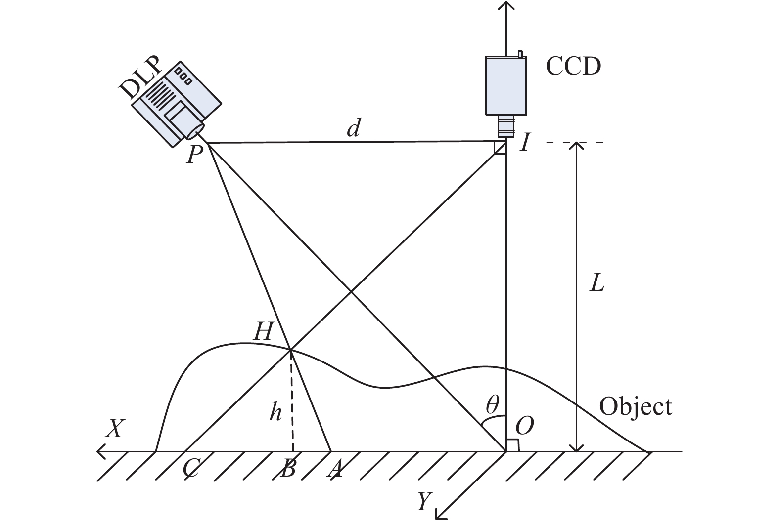
    Fig. 1. Schematic diagram of PMP method
    Schematic diagram of traditional calibration method
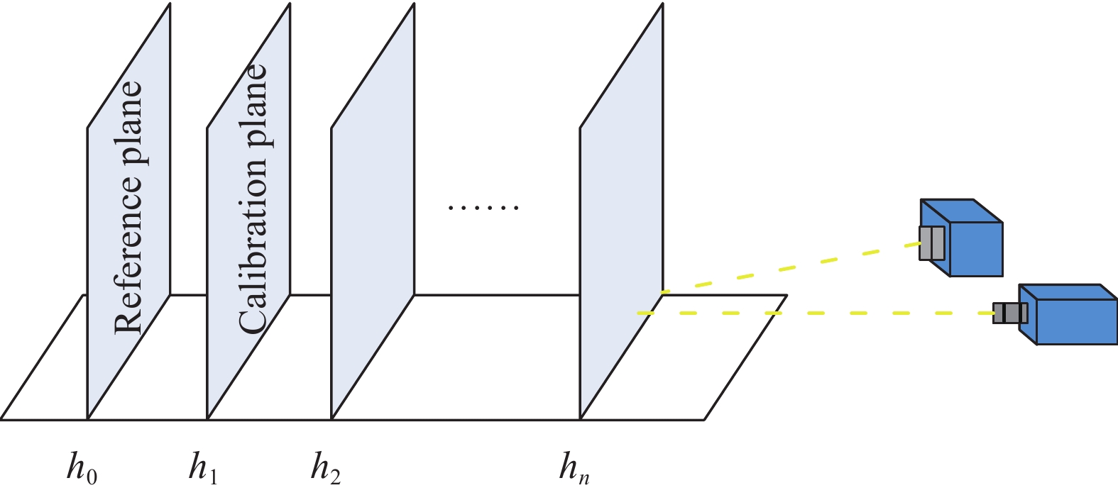
    Fig. 2. Schematic diagram of traditional calibration method
    Schematic diagram of new calibration method
    Fig. 3. Schematic diagram of new calibration method
    Circle marker. (a) Circle center; (b) Partial enlargement of the figure (a)
    Fig. 4. Circle marker. (a) Circle center; (b) Partial enlargement of the figure (a)
    Schematic of the proposed method
    Fig. 5. Schematic of the proposed method
    Measurement with the traditional method. (a) The deformed fringe pattern modulated by the block; (b) Part of a deformed fringe pattern; (c) The continuous phase value; (d) 3D point cloud data of a block
    Fig. 6. Measurement with the traditional method. (a) The deformed fringe pattern modulated by the block; (b) Part of a deformed fringe pattern; (c) The continuous phase value; (d) 3D point cloud data of a block
    Measurement with the proposed method. (a) The calibration system; (b) 3D point cloud data of a block
    Fig. 7. Measurement with the proposed method. (a) The calibration system; (b) 3D point cloud data of a block
    Measurement data of the sphere. (a) Measured sphere; (b) The deformed fringe pattern modulated by the sphere; (c) Continuous phase distribution
    Fig. 8. Measurement data of the sphere. (a) Measured sphere; (b) The deformed fringe pattern modulated by the sphere; (c) Continuous phase distribution
    Reconstruction results of the sphere. (a) 3D shape by the traditional method; (b) 3D shape by the proposed method
    Fig. 9. Reconstruction results of the sphere. (a) 3D shape by the traditional method; (b) 3D shape by the proposed method
    The part of cutaway view for a column
    Fig. 10. The part of cutaway view for a column
    Reconstruction results of the sphere. (a) Captured deformed pattern; (b) Reconstructed 3D shape
    Fig. 11. Reconstruction results of the sphere. (a) Captured deformed pattern; (b) Reconstructed 3D shape
    MethodAverage height/mmRMSE/mm
    Traditional10.0180.043
    Proposed10.0470.072
    Table 1. Comparison of the measurement results
    Yanjun Fu, Xiaoqi Cai, Kejun Zhong, Baiheng Ma, Zhanjun Yan. Method for phase-height mapping calibration based on fringe projection profilometry[J]. Infrared and Laser Engineering, 2022, 51(4): 20210403
    Download Citation