• Advanced Photonics
  • Vol. 5, Issue 3, 036001 (2023)
Jingxin Zhang1, Peixing Li2, Ray C. C. Cheung2, Alex M. H. Wong2、3、*, and Jensen Li1、*
Author Affiliations
  • 1The Hong Kong University of Science and Technology, Department of Physics, Hong Kong, China
  • 2City University of Hong Kong, Department of Electrical Engineering, Hong Kong, China
  • 3City University of Hong Kong, State Key Laboratory of Terahertz and Millimeter Waves, Hong Kong, China
  • show less
    DOI: 10.1117/1.AP.5.3.036001 Cite this Article Set citation alerts
    Jingxin Zhang, Peixing Li, Ray C. C. Cheung, Alex M. H. Wong, Jensen Li. Generation of time-varying orbital angular momentum beams with space-time-coding digital metasurface[J]. Advanced Photonics, 2023, 5(3): 036001 Copy Citation Text show less
    Time-varying OAM beam generation. (a) Time-varying OAM beam with topological charge l(t) varying from 0, 1, 2, 3, 4(−4), −3, −2, and −1 periodically in time, with envelope phase profile [omitting exp(jωt) for brevity] shown at different layers in time. The cyan and red curved surfaces geometrically join up the 0 and π phase on different layers, showing a twist completing one cycle in the clockwise direction defined with winding number w=−1. The beam is generated by a space-time-coding digital metasurface controlled with FPGA. (b) Digital coding scheme of the metasurface with 3-bit coding digits “1” to “8” representing the 0 deg to 315 deg in every 45 deg for the reflection phase profile (in addition to reflection from a perfect metal) at each time instance. The black stars mark the twisted trajectory of zero phase position with coding digit “1.”
    Fig. 1. Time-varying OAM beam generation. (a) Time-varying OAM beam with topological charge l(t) varying from 0, 1, 2, 3, 4(4), 3, 2, and 1 periodically in time, with envelope phase profile [omitting exp(jωt) for brevity] shown at different layers in time. The cyan and red curved surfaces geometrically join up the 0 and π phase on different layers, showing a twist completing one cycle in the clockwise direction defined with winding number w=1. The beam is generated by a space-time-coding digital metasurface controlled with FPGA. (b) Digital coding scheme of the metasurface with 3-bit coding digits “1” to “8” representing the 0 deg to 315 deg in every 45 deg for the reflection phase profile (in addition to reflection from a perfect metal) at each time instance. The black stars mark the twisted trajectory of zero phase position with coding digit “1.”
    Metasurface design and reflection responses. (a) Photo of the fabricated space-time-coding digital metasurface. (b) Detailed geometrical parameters of the element structure. (c), (d) Simulated reflection amplitude and phase of the metasurface at different bias voltages, where the vertical orange line indicates the operating frequency at 11 GHz. (e), (f) Measured reflection amplitude and phase of the metasurface at different bias voltages.
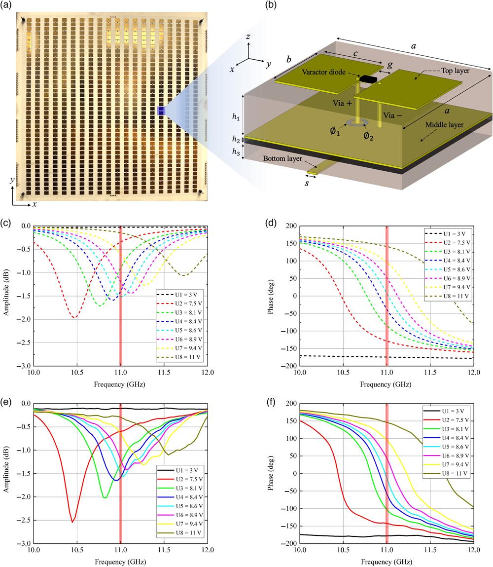
    Fig. 2. Metasurface design and reflection responses. (a) Photo of the fabricated space-time-coding digital metasurface. (b) Detailed geometrical parameters of the element structure. (c), (d) Simulated reflection amplitude and phase of the metasurface at different bias voltages, where the vertical orange line indicates the operating frequency at 11 GHz. (e), (f) Measured reflection amplitude and phase of the metasurface at different bias voltages.
    Dynamic measurement of time-varying OAM field pattern (w=−1) using the two-probe technique. (a) Experimental scenario of dynamic electric field pattern measurement of the generated time-varying OAM beams. The probe S is movable to scan the field, and the reference probe R is fixed for synchronization processing. (b) Measured near-field amplitude and phase patterns of the time-varying OAM beams at different time instances in one period of T. The field patterns consisted of 45×45=2025 pixels with a range of 0.6 m×0.6 m.
    Fig. 3. Dynamic measurement of time-varying OAM field pattern (w=1) using the two-probe technique. (a) Experimental scenario of dynamic electric field pattern measurement of the generated time-varying OAM beams. The probe S is movable to scan the field, and the reference probe R is fixed for synchronization processing. (b) Measured near-field amplitude and phase patterns of the time-varying OAM beams at different time instances in one period of T. The field patterns consisted of 45×45=2025  pixels with a range of 0.6  m×0.6  m.
    Spectrum analysis of time-varying OAM. (a) OAM intensity and phase spectrum of the measured time-varying OAM beams at different instants of time. (b) Measured and theoretical OAM mode purity for the dominant l(t). (c) Comparison of measured and theoretical twisting phases for different time instants of dominant l(t).
    Fig. 4. Spectrum analysis of time-varying OAM. (a) OAM intensity and phase spectrum of the measured time-varying OAM beams at different instants of time. (b) Measured and theoretical OAM mode purity for the dominant l(t). (c) Comparison of measured and theoretical twisting phases for different time instants of dominant l(t).
    Jingxin Zhang, Peixing Li, Ray C. C. Cheung, Alex M. H. Wong, Jensen Li. Generation of time-varying orbital angular momentum beams with space-time-coding digital metasurface[J]. Advanced Photonics, 2023, 5(3): 036001
    Download Citation