Jingxin Zhang, Peixing Li, Ray C. C. Cheung, Alex M. H. Wong, Jensen Li, "Generation of time-varying orbital angular momentum beams with space-time-coding digital metasurface," Adv. Photon. 5, 036001 (2023)
Copy Citation Text
The recently proposed extreme-ultraviolet beams with time-varying orbital angular momentum (OAM) realized by high-harmonic generation provide extraordinary tools for quantum excitation control and particle manipulation. However, such an approach is not easily scalable to other frequency regimes. We design a space-time-coding digital metasurface operating in the microwave regime to experimentally generate time-varying OAM beams. Due to the flexible programmability of the metasurface, a higher-order twist in the envelope wavefront structure of time-varying OAM beams can be further designed as an additional degree of freedom. The time-varying OAM field patterns are dynamically mapped by developing a two-probe measurement technique. Our approach in combining the programmability of space-time-coding digital metasurfaces and the two-probe measurement technique provides a versatile platform for generating and observing time-varying OAM and other spatiotemporal excitations in general. The proposed time-varying OAM beams have application potentials in particle manipulation, time-division multiplexing, and information encryption.
Electromagnetic waves carry both linear and angular momenta. Specifically, the latter can be decomposed into spin angular momentum (SAM) and orbital angular momentum (OAM).1 Although SAM is associated with polarization, OAM is associated with the helical wavefront in azimuthal angle with an integer topological charge .2 OAM beams with distinct topological charges are mutually orthogonal, allowing them to carry information and to be multiplexed.3–7 The increased channel capacity and spectral efficiency with OAM multiplexing can thus be useful in fiber-based and free-space communications, with both prospects and challenges.8 Moreover, OAM beams with nonzero topological charges have phase singularity with vanished intensity at the beam center, which are useful for optical trapping and lattices.9–12
To further unlock the full potential of OAM, there have been persistent efforts in generalization of the concept. Spatiotemporal optical vortex beams13–19 have been recently demonstrated with phase singularities generally in space-time coordinates, forming higher-order structures, such as a phase-singular ring. Rego et al.20 proposed a kind of extreme-ultraviolet beam with time-varying OAM arising from high-harmonic generation. The topological charge varies in time periodically, giving a time-dependent phase profile and inducing a self-torque of light. It can be potentially applied to various scenarios, including particle manipulation,21–23 Bose–Einstein condensation,24,25 and Floquet topological dynamics.26,27 However, such a high-harmonic approach in generating time-varying OAM is not easily applicable to other frequency regimes, hindering further demonstrations. Alternatively, Sedeh et al.28 proposed an optical metasurface with a spiral-staircase profile of modulation frequencies to implement time-varying OAM. In fact, such an approach can be feasible and generalized through a space-time-coding digital metasurface with field-programmable-gate-array (FPGA) technology, particularly in the microwave regime.29–37 In such a case, different metasurface responses can be digitized by controlling the bias voltages with the adoption of FPGA, which offers the metasurface powerful programmability for space-time modulation.
In this work, we experimentally construct and observe time-varying OAM beams using a space-time-coding digital metasurface in the microwave regime. We also introduce a higher-order twist in the wavefront structure of time-varying OAM beams, enabled by the flexible programmability of the metasurface. To observe the complex field pattern being varied in time, we use a two-probe measurement technique to dynamically map the time-varying OAM field pattern. A space-time-coding digital metasurface together with a two-probe field-mapping technique provides a versatile platform to construct and observe time-varying OAM and spatiotemporal excitations in general. The proposed time-varying OAM beams can be further used in particle manipulation, time-division multiplexing, and information encryption.
Sign up for Advanced Photonics TOC. Get the latest issue of Advanced Photonics delivered right to you!Sign up now
2 Materials and Methods
2.1 Theory of Time-Varying OAM Beams Generation
To generate normal OAM beams with phase profile by a metasurface [time harmonic convention , the direct way is to create an azimuthal phase gradient of the scattered field with topological charge , while for the time-varying OAM beams, the phase profile turns to be with topological charge varying linearly with time,20 manifesting a time-dependent azimuthal phase gradient decided by . To realize such properties, we consider a space-time-coding digital metasurface with active modulation of reflection phase depending on both azimuthal angle and time as When the is chosen to vary linearly in time with a modulation period , we obtain consecutive integer from 0 to at time instants . The metasurface is divided into finite azimuthal sectors to implement the different OAM profiles. Due to the discretization of the metasurface, the OAM phase profiles with and are in fact equivalent to each other by assuming each sector can only give a particular reflection phase at a particular time instance, so the value of cannot increase to infinity but repeats from to in every period .28 Under a monochromatic illumination at signal radial frequency on the metasurface with spatiotemporal phase modulation , the reflected field becomes when the modulation frequency is much lower than the signal frequency. The describes the spatial dependency of the scattered field in cylindrical coordinates , and the coefficient of becomes as , which denotes the time-varying topological charge of the OAM beam.
With the flexible programmability of the metasurface, the envelope wavefront structure of the above-mentioned time-varying OAM beams can be further designed. We modify the spatiotemporal phase modulation in Eq. (1) as where and is defined as the time-dependent twisting angle. As an example here, we design as , a linear function in time, where is defined as the winding number of the time-varying OAM beam. Then the reflected field can be expressed as
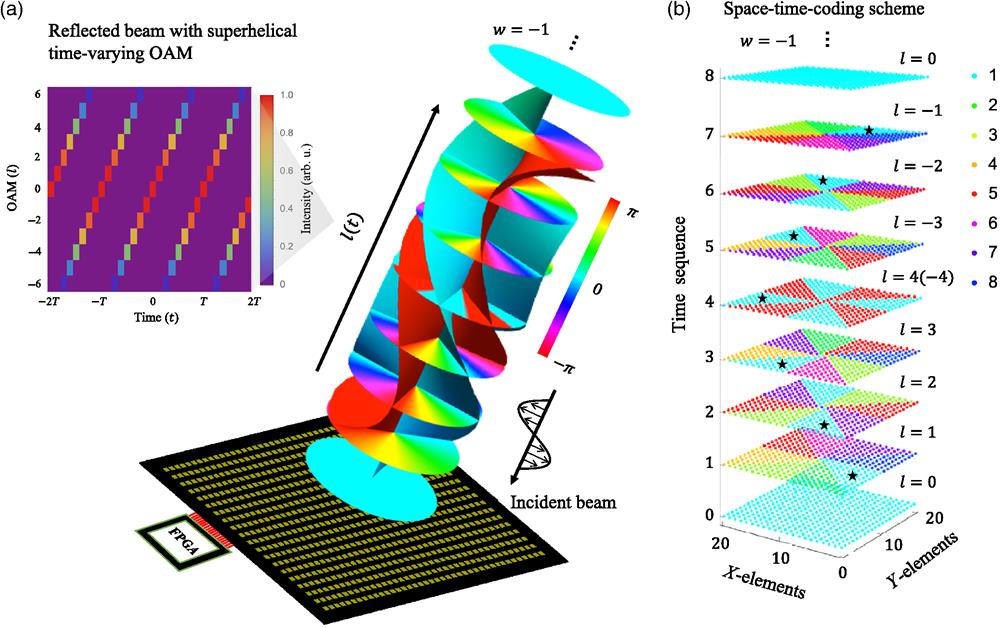
Here we consider the case of , for illustration purposes. As shown in Fig. 1(a), the envelope wavefront structure of the reflected beam has been plotted, where the constant phase contour is only about the slowly varying modulation phase envelope, and the much faster phase variation at signal frequency is omitted in the drawing for brevity. As can be seen, different time layers at show different OAM phase profiles, taken as , 1, 2, 3, , , , periodically. We remark that it is a superposition of two OAM modes: and at . By “geometrically” joining up all the zero phase (cyan color) and phase (red color) at different time instances, the wavefront structure shows up a higher-order twist for a nonzero ( in this example) compared with case (see Fig. S1 in the Supplementary Material). In other words, the envelope wavefront of the time-varying OAM beam () is further twisted with round in one period of . Here we only consider the integer case of as an example, while the can be other integers and fractional values (see Sec. 4 for details). The winding number can be seen as an additional degree of freedom in constructing the time-varying OAM beams. More information can be encoded by designing the to increase the channel capacity for data transmission. And we provide an example of winding number implementation and measurement with experimental demonstrations, as shown in Sec. 3.2.
Figure 1.Time-varying OAM beam generation. (a) Time-varying OAM beam with topological charge varying from 0, 1, 2, 3, , , , and periodically in time, with envelope phase profile [omitting for brevity] shown at different layers in time. The cyan and red curved surfaces geometrically join up the 0 and phase on different layers, showing a twist completing one cycle in the clockwise direction defined with winding number . The beam is generated by a space-time-coding digital metasurface controlled with FPGA. (b) Digital coding scheme of the metasurface with 3-bit coding digits “1” to “8” representing the 0 deg to 315 deg in every 45 deg for the reflection phase profile (in addition to reflection from a perfect metal) at each time instance. The black stars mark the twisted trajectory of zero phase position with coding digit “1.”
In our paper, we generate the time-varying OAM beams with and , respectively. The case of is illustrated in the main text, whereas the results of can be found in Sec. 2 in the Supplementary Material for comparison. To generate the time-varying OAM beam with by a space-time-coding digital metasurface, as shown in Fig. 1(b), we divide the metasurface into azimuthal sectors, and each sector is dynamically controlled with 3-bit coding digits “1” to “8,” representing the reflection phase from 0 deg to 315 deg in every 45 deg (in addition to reflection from a perfect metal). The space-time-coding scheme is designed according to the phase term in Eq. (4), with winding number . For easier implementation, we only adopt eight different time frames with eight coding states in a period of to generate the integer , whereas the fractional OAM states are not considered for the implementation. The details for the space-time modulation scheme can be found in Tables S1 and S2 in the Supplementary Material. In Fig. 1(b), the corresponding phase states represented by different colors show an -related distribution at each time layer, and the black stars mark the azimuthal positions of zero phase (coding digit “1”) showing the higher-order twist in the envelope wavefront structure of time-varying OAM with . The location of the zero phase takes a time of for one revolution. Here we emphasize that the upper limit of the modulation frequency of the space-time-coding digital metasurface is typically within the megahertz range,29–34 which is much slower than the signal frequency (gigahertz) in the microwave regime. Therefore, the modulation mechanisms and the operation only focus on the modulation envelope rather than the carrier signal. In our current work, the time-varying control is achieved through adiabatic field control at the fundamental frequency. It is also possible to instruct the output beam to another ’th harmonic by adding an additional phase to the reflection phase.
2.2 Space-Time-Coding Digital Metasurface
To demonstrate the above-illustrated concept, as shown in Fig. 2(a), we design and fabricate a space-time-coding digital metasurface with elements operating at 11 GHz. Each element is loaded with a varactor diode, whose capacitance changes with the bias voltage, leading to the frequency shift of the dipole resonance of the metasurface so that the reflection phase can be varied in time. We note that we apply the commonly used element structure embedded with a varactor diode for the realization of digital-coding metasurface as previous work,30,31,33 but now with a biasing network design appropriate for generating time-varying OAM in Fig. S3 in the Supplementary Material and the digital coding scheme in space-time domain in Fig. 1(b). The 3D structure of each element of the proposed metasurface is illustrated in Fig. 2(b). The geometrical parameters of the element are chosen as , , , Ø, Ø, , , , , and . The element is composed of three copper layers printed on two substrate layers (Rogers 4003C, , ) and a bonding layer (Rogers 4450F, , ). On the top layer, two rectangular metal patches are connected by a varactor diode (MAVR-000120-14110P) soldered on the metasurface by the surface mounting technology (SMT). One patch is connected to the middle layer through metallic via −. Another patch is connected to the bottom layer through via +, which is electrically isolated from the middle layer by a hollowed ring. The middle layer connects to negative “−” electrode and the bottom layer connects to positive “+” electrode, providing the bias voltage to the varactor diode through the two metallic vias.
Figure 2.Metasurface design and reflection responses. (a) Photo of the fabricated space-time-coding digital metasurface. (b) Detailed geometrical parameters of the element structure. (c), (d) Simulated reflection amplitude and phase of the metasurface at different bias voltages, where the vertical orange line indicates the operating frequency at 11 GHz. (e), (f) Measured reflection amplitude and phase of the metasurface at different bias voltages.
To characterize the reflection responses of the metasurface, full-wave simulations are performed (CST Microwave Studio). The simulated reflection amplitude and phase at eight bias voltages from U1 to U8 are shown in Figs. 2(c) and 2(d). As can be seen, we acquire eight different reflection phases at 11 GHz with a 45-deg gradient covering a range of 315 deg, which can be used as 3-bit coding digits from “1” to “8.” The corresponding amplitudes at 11 GHz are not uniform, and their differences are controlled within . The experimental results agree well with the simulation results, as shown in Figs. 2(e) and 2(f), which are obtained by measuring the reflection coefficient of the metasurface in setting the bias voltages for all the elements to be the same one. In addition, we simulate the near-field patterns of the time-varying OAM beam at different time instances, which can be found in Fig. S2 in the Supplementary Material.
3 Results
3.1 Dynamic Field Pattern Measurement of the Time-Varying OAM Beams
For experimental demonstration of the time-varying OAM beams generated by the space-time-coding digital metasurface, we directly measure the time-varying field pattern, including amplitude and phase information at various instants of time. A vector network analyzer can be used in the continuous wave (CW) time sweep mode to measure time-domain -parameters. However, as the measured -parameters in the time domain can start at any instant within one modulation cycle, the fields scanned at different positions cannot be compared with each other. Here in addition to the scanning probe S, we add a reference probe R whose position is fixed, and the two probes are measured synchronously. Then the results from the probe R do not vary against different probe S positions except for a time shift, which can now be used to align the -parameters between signals probed at different positions (see the schematic in Figs. S4 and S5 in the Supplementary Material for more details). In our experiment, as shown in Fig. 3(a), the space-time-coding digital metasurface is applied with 3-bit digital coding sequence [Fig. 1(b)], to generate the time-varying OAM beam with a modulation period around with winding number . The feed horn is placed 0.2 m away from the reflective metasurface to give a monochromatic excitation signal at 11 GHz polarized in the direction. Note that the feed horn is located at the beam null of the reflected OAM beams to minimize the block effect. Two open-ended waveguide probes (WR-90) are placed 0.44 m away from the metasurface. The stimulus condition of the vector network analyzer (Agilent N5230A) is set as CW time sweep mode at 11 GHz, with a sweep time of 10 ms. Then a time-domain -parameter waveform (complex value) with a temporal resolution of can be measured. By simultaneously measuring the probe R and probe S in the scanning range of , with a step size of 13.6 mm, groups of data are obtained. By performing data postprocessing for the received signals at all scanning positions (see details in Sec. 4 in the Supplementary Material), we can map the dynamic amplitude and phase field pattern of the generated time-varying OAM beams at any moment during a modulation cycle.
Figure 3.Dynamic measurement of time-varying OAM field pattern () using the two-probe technique. (a) Experimental scenario of dynamic electric field pattern measurement of the generated time-varying OAM beams. The probe S is movable to scan the field, and the reference probe R is fixed for synchronization processing. (b) Measured near-field amplitude and phase patterns of the time-varying OAM beams at different time instances in one period of . The field patterns consisted of with a range of .
Figure 3(b) illustrates the measured near-field amplitude and phase patterns of the time-varying OAM beams with at different instants of time in one period of , showing the time-varying topological charge in consecutive integer values. The amplitude patterns with nonzero show a dark area in the center due to the phase singularity along the OAM beam axis. The nonuniform intensity of the OAM along the azimuthal direction is caused by the differences in reflection amplitude for different coding states at 11 GHz, as shown in Fig. 2(e). In addition, for these phase patterns, a multiannular structure can be observed because the incident beam is seen as a spherical wave when the feed horn is placed not far away enough from the metasurface. The phase pattern of shows an almost homogeneous phase in the central area and the other patterns with nonzero show different spiral fringes determined by the value of . The change of OAM is clearly observable as the spiral fringes vary in time. We observe that these spiral fringes are disconnected from the peripheral phase profile due to the finite size of the fabricated metasurface. Some noise points can be found in the measured field pattern, which is caused by the synchronization error when using two-probe dynamic field mapping.
3.2 OAM Spectrum Analysis and Winding Number Decoding
To further evaluate the OAM mode purity and decode the winding number of the generated time-varying OAM beams, first we calculate the OAM intensity spectrum by decomposing the field into different angular momenta,38,39where denotes the measured time-varying OAM field in Fig. 3(b), and are the radial range of the electric field, and is the OAM component to check on the measured field. The OAM intensity spectra for the measured field at different instants of time are shown in Fig. 4(a). Each spectrum contains different components, and it is normalized to the maximum component. At each time instant, the OAM field has a topological charge . As can be seen, the OAM intensity spectrum at each time instant is relatively dominated by the component (marked by a red star), compared with the parasitic ones, showing that the generated beam contains time-varying OAM modes as the theoretical expectation shown in Fig. 1(a). Here we define OAM mode purity as and obtain the measured mode purity for the dominant topological charges , as shown in the black bar in Fig. 4(b). On the other hand, we can also calculate the theoretical results for the mode purity, as shown in the same figure. We note that the theoretical mode purity is not 100% due to the spatial discretization of the profile into eight sectors of constant reflection phases, so that the theoretical mode purity deceases from 100% at to around 50% at . Nevertheless, the experimentally extracted mode purity agrees well with the theoretical results. The difference between measured and theoretical results comes from the near-field pattern measurement error, nonuniform azimuthal intensity, and the feed-horn blocking effect. In addition, the insufficient scanning range of the field pattern also leads to the lower mode purity, especially for the case.
Figure 4.Spectrum analysis of time-varying OAM. (a) OAM intensity and phase spectrum of the measured time-varying OAM beams at different instants of time. (b) Measured and theoretical OAM mode purity for the dominant . (c) Comparison of measured and theoretical twisting phases for different time instants of dominant .
Next, we investigate the winding (or twisting) wavefront structure of the time-varying OAM beam. We numerically obtain the field arriving at the measurement plane for a metasurface with zero winding structure using the Fresnel diffraction formula and denote it as at different time instants (see Sec. 1 in the Supplementary Material for details). Then the additional phase introduced by the twisting can be obtained from the measured field using which is called twisting phase here; it should be theoretically introduced by Eq. (3), becoming (mod ). In Fig. 4(c), we plot the twisting phase at the eight time instances using open circles. They also agree well with the theoretical results (quadratic in time , with and ), plotted as the red line in the same figure. The results confirm the realization of the winding number. This also indicates the winding number is a real degree of freedom of time-varying OAM and can be used for information encoding, and it can be decoded from the measured OAM field patterns. This additional degree of freedom is enabled by the flexible programmability of the space-time coding metasurface.
4 Discussion
The space-time-coding digital metasurfaces provide a powerful and flexible platform to manipulate the electromagnetic waves both in the spatial and temporal domains, which contributes to the realization of time-varying OAM beam generation in the current work. In fact, we have only considered the integer case of winding number as a typical example. The extension to other values, including fractional value, can also be realized with an adjustment of the space-time-coding scheme. For , the azimuthal position of zero phase needs to take a time of for a full cycle. Then the coding sequence needs to be modified with a longer period of . For , the zero phase rotates around circles in one period of . The number of OAM modes varying in one period of needs to be added to acquire more frames of OAM patterns to characterize the winding number of time-varying OAM beams.
For experimental verification of the time-varying OAM beam generation, one difficulty is the dynamic measurement of the time-varying amplitude and phase field pattern. The traditional microwave near-field scanning system (which conventionally features one probe) cannot fulfill our demands. The usage of a two-probe measurement technique can observe the OAM amplitude and phase pattern varying in the time domain, which enables the time-varying OAM validation in this work. We note that the S11 signal at the feed horn can also act as the second probe, serving similar purpose of the probe R. Such a two-probe technique might also be applied in other time-varying scenarios to measure other spatiotemporal excitations.
Our proposed metasurface with space-time phase modulation is implemented in the microwave regime. However, it can be extended to other frequency regimes with higher frequencies in terms of principle. From the perspective of implementation, we will need a meta-atom response that can be controlled and tunable in space and time in that frequency regime. For example, in the terahertz regime, by dynamically exciting different metamaterial structures, a reconfigurable wavefront is possible.40 In the optical regime, a space-time varying profile of indices can be achieved by the nonlinear Kerr effect.41 As a brief picture, a micromirror device or an spatial light modulator can be used to excite different locations on metasurface to change the local indices, e.g., using the nonlinear Kerr effect, so that the spatiotemporal profile of the OAM in this work can be achieved based on the elaborated principle. The advantages of introducing time modulation can be twofold. An additional degree of freedom in controlling OAM with a time-varying profile can be used to enhance communication capacity as an immediate application.42 Moreover, the inhomogeneous OAM profile in both the spatial and temporal domains can also be potentially useful for obtaining unconventional particle trapping, sorting dynamics, and controlling particle trapping stability.43
In summary, we have experimentally generated time-varying OAM beams by a space-time-coding digital metasurface in the microwave regime. A higher-order twist described by winding number in the envelope wavefront structure of time-varying OAM beams is proposed and demonstrated. We develop a two-probe measurement technique to dynamically map the time-varying OAM field patterns and perform the OAM spectrum analysis. The proposed time-varying OAM beams provide new routes in particle manipulation, time-division multiplexing, and information encryption.
Acknowledgment
Acknowledgment. This work was supported by the Hong Kong Research Grants Council (Project Nos. R6015-18 and C6012-20G).
Jingxin Zhang received his BS and MS degrees from Beihang University, Beijing, China. He is currently a PhD student, supervised by Prof. Jensen Li, in the Physics Department at the Hong Kong University of Science and Technology, Hong Kong, China. His research interests are focused on programmable digital-coding metasurface, time-varying metamaterials, and machine-learning techniques with the application of beam steering, harmonics manipulation, information encryption, and orbital angular momentum generation.
Peixing Li is currently a final-year undergraduate student in the Department of Electrical Engineering at the City University of Hong Kong. He is conducting research supervised by Dr. Alex M. H. Wong and is a member of the Departmental Undergraduate Research Fellowship. His coursework and research focus on applied electromagnetics, microwave engineering, antenna design, and metamaterials. His research experience includes digital modulation mechanism of time-varying systems, programmable metasurface, and antenna design and measurement.
Ray C. C. Cheung received his BEng (Hons.) and MPhil degrees in computer engineering and computer science and engineering from the Chinese University of Hong Kong and the DIC and PhD degrees in computing from the Imperial College London. He received the Hong Kong Croucher Foundation Fellowship and moved to Los Angeles in Electrical Engineering Department at UCLA. He is an associate professor in the Department of Electrical Engineering at the City University of Hong Kong and at the Digital Systems Laboratory. His current research interests include cryptographic hardware and processor architecture designs.
Alex M. H. Wong obtained his doctoral degree in electrical engineering from the University of Toronto. He is currently an assistant professor in the Department of Electrical Engineering at the City University of Hong Kong. He is also a member of the State Key Laboratory of Terahertz and Millimeter Waves. His research interests lie in metasurfaces from optical to microwave frequencies and applied electromagnetics in general, with societal applications in telecommunication and biomedicine.
Jensen Li is a professor of physics at the Hong Kong University of Science and Technology. His research focuses on optical metasurfaces, non-Hermitian systems, transformation optics, and acoustic metamaterials, resulting in more than 100 peer-reviewed publications. He has led a collaborative research project on “Non-Hermitian Systems in Optics and Acoustics” across several Hong Kong universities. He was elected Croucher senior research fellow in 2022 and is a member of the Hong Kong Young Academy of Sciences.
Jingxin Zhang, Peixing Li, Ray C. C. Cheung, Alex M. H. Wong, Jensen Li, "Generation of time-varying orbital angular momentum beams with space-time-coding digital metasurface," Adv. Photon. 5, 036001 (2023)