1Key Laboratory for Physical Electronics and Devices of the Ministry of Education & Shaanxi Key Laboratory of Information Photonic Technique, School of Electronic Science and Engineering, Faculty of Electronic and Information Engineering, Xi’an Jiaotong University, Xi’an 710049, China
Optical skyrmions formed by photonic spin–orbit (SO) coupling are of significant interest in high-dimensional optical information processing. We report the formation mechanism and non-Hermitian properties of skyrmion-like states in a circular confinement potential with photonic SO coupling, which is preferably realized in a concave-planar microcavity system. We show that the effective photonic gauge field leads to two split manifolds of degenerate skyrmions whose spin textures can be controlled via the non-Hermitian properties by introducing circularly polarized gain and loss, exhibiting dramatically discrepant evolutions at the two sides of the exceptional point (EP). Furthermore, the lifetime degeneracy can be lifted by spatially inhomogeneous pumping according to the non-Hermitian mechanism, enabling the possibility for the skyrmion laser. By introducing shape asymmetry of the confinement potential, a double EP evolution can be achieved, which allows non-Hermitian control of the SO coupled states with higher degrees of freedom. These results open the way for the non-Hermitian control of photonic spin in confined systems, which would be of great significance for the fundamentals of advanced optical information processing.
1. INTRODUCTION
Skyrmions are topological structures in magnetic materials characterized by a vortex-type distribution of electron spin [1], which are proposed to be applied in high-density data storage and transfer [2]. An ideal skyrmion is a spatially restricted topological structure of three-dimensional (3D) vector field, characterized by the topological number, which is an integer equal to the number of times the 3D vectors wrapping around the unit sphere [3,4] (see Appendix B for details). As photons also carry spin and orbital angular momentum (OAM), optical and plasmonic Skyrmions, featured by the concentric alternation of the photon spin in space, have been demonstrated in evanescent electromagnetic fields [5,6], meta-structures [7], and free space [8,9], and they have been proposed for promising applications in information processing, storage, and transportation [7]. The key mechanism for the formation of optical Skyrmions is the photonic spin–orbit (SO) coupling, which involves the interaction between the photon spin and orbital motion. The SO coupling effect has resulted in various types of photonic Hall effect, chirality of photon transportation, and topological phenomena in both free optics [10–12], dielectrics [13–15], and surface plasmonics [16–20]. One of the most promising on-chip platforms for implementing photonic SO interaction is Fabry–Perot (FP) microcavities with metal mirrors or distributed Bragg reflectors (DBRs), which can support the half-light, half-matter eigenstates of exciton-polaritons [21]. The various types of polarization associated mechanisms, including the cavity transverse-electric transverse-magnetic (TE-TM) splitting, the anisotropy of the active material, the external magnetic field, and the combination of the above, serve as an effective gauge field on the spin of cavity photons. This leads to the research topic of spinoptronics in microcavities, meaning the optical counterparts of spintronics [22]. The mechanism of spinoptronics has led to remarkable physical achievements such as the optical spin-Hall effect [23,24], dark half-solitons [25], Rashba–Dresselhauses SO coupling [26,27], and nontrivial topological bands and valleys [28–31]. Propagating photonic skyrmions have also been proposed and demonstrated by resonantly pumping such systems with linearly polarized photons [22,32].
In addition to the exotic band structures and dynamics of two-dimensional (2D) cavity photons and polaritons, the SO coupling within a photonic potential of lateral confinement also leads to interesting physical phenomena. In the confined structure of circular symmetry, the cavity photons form a series of zero-dimensional (0D) eigenstates of which the higher-order transverse modes carry Laguerre–Gaussian (LG)-type OAM [33]. The SO coupling in the confined potential, i.e., the interaction between the photonic OAM and spin angular momentum (SAM) induced by the cavity TE-TM splitting, has led to new eigenstates of spin vortices in open-access microcavities [34] and the benzene-like photonic molecules [35]. It is shown that the relation between such vector vortex states in the first excited manifold, i.e., with OAM and SAM , could be described by a generalized theoretical frame of higher-order Poincaré sphere (HOPS) [36,37]. For the higher orders of the excited manifolds with , although there are theoretical prediction and experimental demonstration of part of the possible eigenstates for that display complex polarization patterns showing the feature of skyrmions [34,38], inadequate conclusions might be drawn without the comprehensive understanding of the entire manifold, as will be discussed later.
Meanwhile, the non-Hermitian properties, enabled by the dissipative interaction with the environment, have brought significant interest in microcavity photonics during recent years, revealing rich physics associated with the exceptional point (EP) [39–41]. It is shown that the non-Hermitian properties around the EP can be employed to control the system performance in lasers and sensors [40,42,43]. In polaritonic microcavity systems with SO coupling, Voigt EPs were observed [44] and demonstrated to display a divergent quantum metric [45]. The key feature associated with the non-Hermitian nature is the strong modification of the photon spin, which is characterized by the measured polarization distribution of the photonic bands. Therefore, one can certainly expect that, by applying the non-Hermitian mechanism, an efficient control of the spin textures of the higher excited manifolds in confined systems can be achieved, which nevertheless requires, first of all, a decent theoretical model to describe such a system.
Sign up for Photonics Research TOC. Get the latest issue of Photonics Research delivered right to you!Sign up now
In this paper, we investigate the eigenstates of the second excited manifold of a circular harmonic potential in an FP microcavity with photonic SO coupling. By applying a theoretical method based on the degenerate perturbation theory in quantum mechanics, we obtain precisely the entire assembly of eigenvalues and eigenstates. We show that, under the effective gauge field induced by the TE-TM splitting, degenerate skyrmions constitute two new manifolds of eigenstates, followed by the non-Hermitian control of the skyrmion states presented in a logical order. (1) The polarization textures of the degenerate skyrmions can be controlled via the non-Hermitian effects of the circularly polarized gain and loss, exhibiting a parallel movement on the Poincaré sphere before reaching the EP, and a longitudinal movement toward the poles after passing the EP. (2) The degeneracy of the skyrmions can be lifted by introducing spatial inhomogeneity of the circularly polarized gain and loss. (3) In a more complicated situation that involves potential asymmetry, a double EP configuration can be established, manifesting non-Hermitian control with multiple degrees of freedom. Our results initiate the unique methodology for non-Hermitian control of photon spin in confined systems and would play a significant role in developing advanced mechanisms for on-chip polarization control of light.
2. FORMATION OF OPTICAL SKYRMIONS IN CONFINED SYSTEMS WITH TE-TM SPLITTING
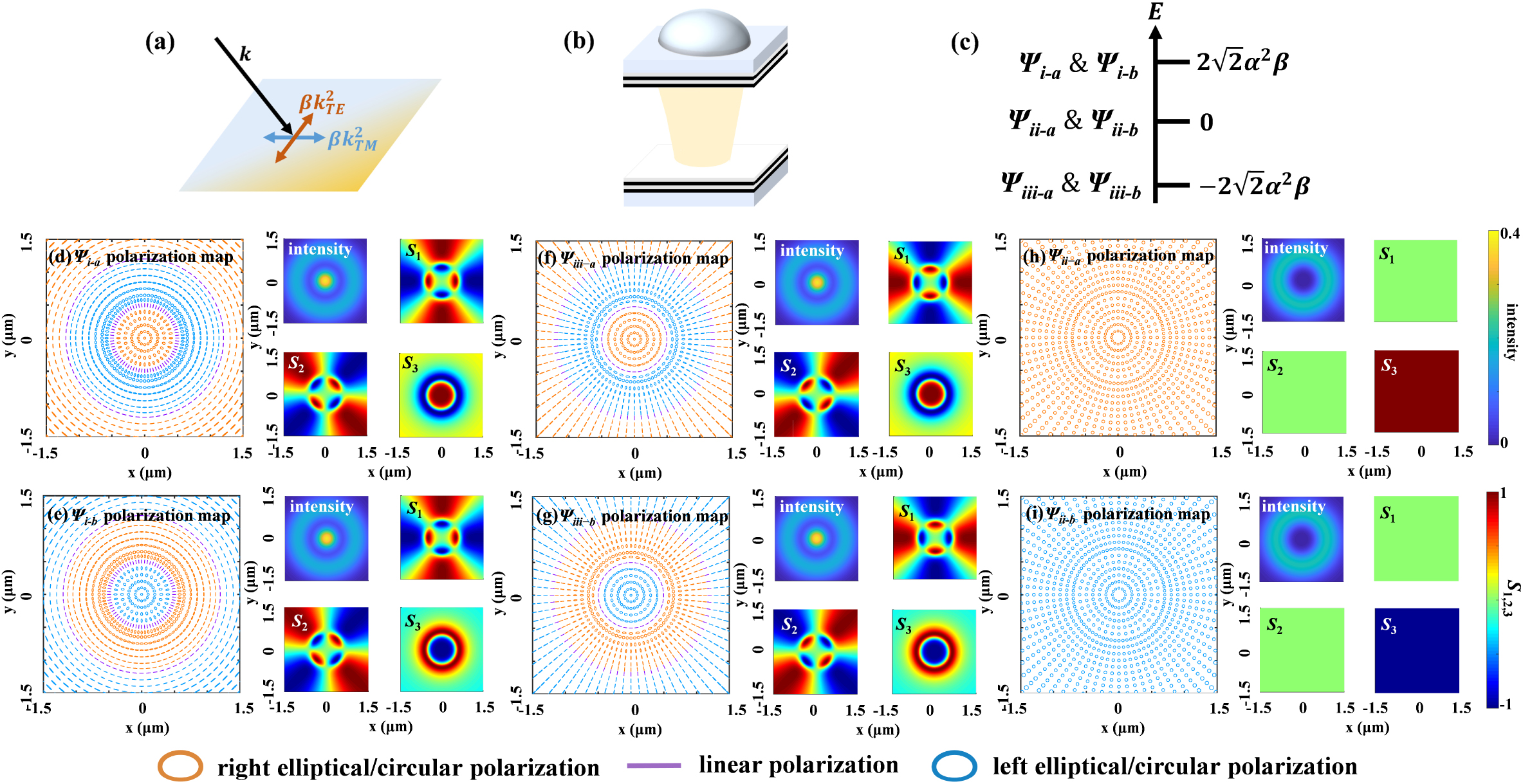
The TE-TM splitting in an FP microcavity is induced by the difference of surface reflectance at the cavity mirrors, which defines two non-degenerate polarization directions associated with the in-plane wave vector, as shown in Fig. 1(a), known as the TE- and TM-polarized cavity modes. The TE-TM splitting serves as an effective gauge field introducing SO coupling of the 2D photons [23,46]. When the cavity photons are confined in a photonic potential, the photonic Hamiltonian can be written as [28,46] in the circular polarization basis where () represents the right (left) circularly polarized photons. In Eq. (1a), is the wave vector composed of two components and , , with () corresponding to the transverse (longitude) effective polariton mass. represents the confinement potential and is the TE-TM splitting term with the polar angle. The Hamiltonian of the free 2D photons can be written in the form of , where represents the kinetic and potential energies, is a column vector consisting of Pauli matrices, and is the effective gauge field [23]. A confinement potential can be realized either by etching the FP microcavity into micropillars [47] or using the open-access microcavity structure consisting of a microscale concave mirror [33,48], as illustrated in Fig. 1(b). When the confinement potential is much stronger than the eigenenergy splitting induced by the TE-TM SO coupling, we can apply the perturbation theory, where the terms of TE-TM splitting are treated as perturbation. Such perturbation theory is proved to fit well with the situation of open-access microcavities, where the concave-planar mirror complex provides very deep confinement potential [34]. The circular-shaped confinement can be expressed as a potential for a harmonic oscillator , with determining the confinement strength. The eigenstates of the unperturbed cavity photons, i.e., when , under circular symmetry are the LG modes, which is denoted as , where represent right- and left-circular polarization, while represents the radial (azimuthal) quantum number. The LG modes are -degenerate, forming a six-dimensional (6D) orthogonal basis in the second excited manifold, in which α is the parameter determining the mode size, given by . The total angular momentum, defined as with representing the quantum number of SAM, has possible values of , or 3, as shown in Table 1.
Total Angular Momentum of the Second Excited Manifold LG Modesa
0
1
1
0
−1
−1
2
1
3
2
−1
1
−2
1
−1
−2
−1
−3
respectively correspond to polarized photons.
Figure 1.Polarization textures of the eigenstates of the second excited manifold. (a) Schematic of the TE-TM splitting characterized by . (b) Sketch of an open-access microcavity; the concave-planar mirror configuration provides the confined potential . (c) Energy levels of the eigenstates under the effect of TE-TM splitting. is the parameter determining mode size. (d)–(i) Left panels, polarization textures of each eigenstate which is instructed in the main text; right panels, the four small graphs representing the intensity distribution, Stokes components , , and . The states presented in (d) and (e), (f) and (g), (h) and (i) are all twofold degenerate in energy. The following parameters are used: μ, μ.
We apply the degenerate perturbation theory (see Appendix A for details) for nonzero , which results in a perturbation matrix of the zeroth order in the 6D basis , in which the unperturbed eigenenergy of the second excited manifold is set to be zero and is applied hereafter. The matrix yields the new eigenenergies, and the new corresponding eigenstates,
The eigenenergies and the polarization textures of the eigenstates are plotted in Fig. 1(c) and Figs. 1(d)–1(i), respectively. The TE-TM splitting partially lifts the degeneracy of manifold, resulting in three energy levels, which are all double-degenerate. As the polarization patterns of the states are very complicated, we adopt a reader-friendly method to display them: the shapes (circular, elliptical, and linear) of the drawings represent the calculated circular polarization degree while the colors represent the direction of the SAM, with orange, blue, and purple meaning the right circular (elliptical), left circular (elliptical), and linear polarizations, respectively. The states, being the bare LG states of , correspond to vector vortices with a topological charge of 2, which are out of the interest of this article. On the contrary, the and states, exhibiting concentric alternating SAM along the radial direction, are optical skyrmions defined by the Stokes vectors on the Poincaré sphere with a skyrmion number of [4,49–52]. The association of these polarization textures with ideal skyrmions is presented in detail in Appendix B. It is obvious from Eqs. (5a), (5b), (5e), and (5f) that the (resp. ) state is non-degenerate with the (resp. ), while they are the coherent superpositions of the (resp. ) modes with a relative phase of 0 and , respectively.
3. NON-HERMITIAN CONTROL OF THE DEGENERATE OPTICAL SKYRMIONS
Despite the skyrmion-like eigenstates given by the perturbation theory, the microcavity is most unlikely to display skyrmion-like optical mode due to the twofold degeneracy. Indeed, since the two skyrmions of (or ) are degenerate, the actual eigenstate can be a coherent superposition of them with any relative phase, yielding an antenna-like mode as shown in Fig. 2(a), which displays linear polarization everywhere. Unfortunately, the degenerate skyrmion modes are the most unstable against asymmetry. If the system is perfectly Hermitian with no dissipation, a slight deformation of the circular potential shape or a tiny defect will lead to a phase pinning between them, resulting in the antenna-like mode, which is, on the contrary, very robust against asymmetric perturbations. Nevertheless, non-Hermitian properties of the cavity photons could allow the skyrmion mode to exist in a special form. The finite coherence (linewidth) due to the dissipation prevents and from going through a coherent interference but instead enables an incoherent superposition, meaning a simple addition of intensities without coherent phase. The resulting mode loses the circular polarization degree due to the incoherent superposition between the left and right circularly polarized light but keeps the linear polarization degree due to the fact that the linear polarization angle is the same for and everywhere. The “incoherent skyrmion” formed in this way is characterized by partial linear polarization features with a concentric alternating polarization degree as calculated in Fig. 2(b) and is, therefore, not exactly a skyrmion due to the loss of circular polarization. Indeed, the experimental observation of such a mode, though not thoroughly explained, can be found in Fig. 3 of Ref. [34]. In fact, incoherent superposition could allow the observation of degenerate modes in their original form without becoming other types of modes via mandatory phase pinning, such as the transverse modes reported in Fig. 3 of Ref. [33], which shows LG-like spatial distribution of intensity by keeping the degeneracy.
Figure 2.Optical skyrmions with lifting and keeping the mode degeneracy. (a) Left panel, polarization textures of the linear combination of degenerate skyrmion-like states with at zero phase difference; right panels, the four small graphs represent the intensity distribution, Stokes components , , and . (b) Polarization degree of the incoherent superposition of the two degenerate skyrmion-like states.
It is obvious that the incoherent states are less interesting due to the lack of coherent phase and polarization. Therefore, it is essential to develop a method to select a coherent single state of the skyrmion, which can be achieved by introducing asymmetry of the non-Hermitian properties. Before going into the details, we first explore the non-Hermitian properties of the degenerate skyrmions by introducing circularly polarized gain and loss, which is associated with the main interest of the article. The corresponding Hamiltonian with the same basis in Eqs. (1b) and (1c) is written as in which is the imaginary part of the uncoupled circularly-polarized cavity photons, being gain for and loss for polarizations. Such circularly-polarized gain in polaritonic microcavities can be provided either by resonant excitation or by non-resonant pumping on valley addressable materials, such as 2D transition metal dichalcogenides (TMDs) [53]. The resulting eigenstates associated with and , derived from the perturbation theory, can be reconstructed by a Hamiltonian in the four-dimensional (4D) basis of where the nonzero elements form two independent matrices. The top-left and the bottom-right ones, corresponding to and states, respectively, display the mathematical forms of standard Hamiltonians for a non-Hermitian system with EPs [39]. The non-Hermitian behavior due to the increase of is demonstrated in Figs. 3(a) and 3(b). At , the eigenstates reduce to the Hermitian situation of degenerate skyrmions and , with an energy (the real part of the eigenvalue) splitting induced by the SO coupling term and balanced gain and loss (the same imaginary part of the eigenvalue equal to zero). With increasing , the bifurcation of the real part is reduced until an EP is reached at the condition , displaying coalesced eigenvalues of both the real and imaginary parts. After passing the EP, the bifurcation of imaginary parts arises, resulting in gain (resp. loss) for the degenerate skyrmions () and () with and , respectively.
Figure 3.Non-Hermitian control of the optical skyrmions. (a) Real and (b) imaginary parts of the eigenvalues as a function of the circular gain and loss . (c) and (d) are, respectively, the same as (a) and (b) except that is enveloped by Gaussian-like spatial distribution with the size parameter μ. The following parameters are used: μ, μ.
The most interesting phenomena lie in the variation of the states with , which is characterized by the polarization textures. Herein we plot the evolution of the polarization textures for in Figs. 4(a)–4(c), while the other skyrmion states follow the same trend. Apparently, the linear polarization angle, i.e., the long axis of the polarization ellipse, at every spatial point rotates with increasing until reaching the maximum rotation of 45° at the EP presented by Fig. 4(b). Then, by further increasing , the degree of circular polarization increases at every spatial point (except those pure polarized, which maintains unchanged), changing toward . Such an evolution could be nicely presented by the traces on the surface of the Poincaré sphere, as displayed in Fig. 4(d), in which we show the trace of the red spatial spot in Figs. 4(a)–4(c). The polarization evolution exhibits a parallel movement of a quarter sphere on the surface until reaching the EP, and then a longitudinal movement toward the north pole after passing the EP, while the points , , and correspond to the situation in Figs. 4(a)–4(c), respectively. As the polarization texture of a skyrmion generally covers the whole surface of the Poincaré sphere, the collective motion of the skyrmion with increasing is equivalent to a parallel rotation of the sphere surface, followed by a density accumulation toward one of the poles, which can be of interest for techniques involving complex polarization control.
Figure 4.Evolution of the polarization textures of in Fig. 3 under non-Hermitian manipulation. (a)–(c) intuitively show the change of polarized state with the increase of with spatially uniform gain and loss corresponding to Figs. 3(a) and 3(b). (d) Poincaré sphere representation of polarization texture evolution. Coordinates , , and are three components of Stokes vectors. Point denotes the polarization state at the red spatial point shown in (a)–(c), which locates at positions , , and when (a) , (b) (at EP), and (c) , respectively. (e) Polarization texture of at the EP with Gaussian-enveloped gain and loss. The four small graphs on the right panels of (a)–(c) and (e) represent the intensity distribution, Stokes components , , and , respectively, while the left panels represent the polarization texture drawings. The following parameters are used: μ, μ.
The evolution of the polarization pattern can be understood by a simple analysis from the general mathematical form of the non-Hermitian Hamiltonian, which can apply to any 2D orthogonal basis. The positive numbers are the coupling coefficients. The eigenvalues and the corresponding eigenstates are An EP occurs when , at which and coalesce. Now we take as an example to analyze the evolution of eigenstates with increasing , while follows similar rules. In the strong coupling regime before reaching the EP, i.e., , can be written as in which the square root terms are real. In this regime, changing means varying the relative phase between the two elements of the basis, which reaches the maximum of at the EP when . On the other hand, in the weak regime after passing the EP, i.e., , has to be written in the following form to keep the square room terms real: In this regime, the relative phase between the two elements of the basis is fixed to be determined by the imaginary unit in the first row. Nevertheless, changing means varying the relative amplitude between the two elements. If the orthogonal basis is chosen to be the polarization, the above evolution corresponds to the one presented in Figs. 4(a)–4(c). For nonzero and , the polarization will not reach pure (the north pole of the Poincaré sphere) until becomes infinite, which is not achievable. Meanwhile, the single states of (the north and south poles of the Poincaré sphere) do not evolve under the gain or loss of the same or orthogonal polarization. The striking fact we can conclude from the above reasoning is that the evolution of a system of high complexity, e.g., the polarization texture of coupled modes with complicated OAM and SO coupling, can be inferred from that of the single uniform state at each pixel. It would be a very interesting topic to investigate how well this principle can apply for various types of complicated systems and at what conditions it holds. At least in our system, it requires the absence of interaction between different spatial points of the LG mode even if they exhibit phase correlation; otherwise, each pixel cannot decide its fate of evolution independently. Indeed, a similar polarization evolution is also seen in other non-Hermitian systems in momentum space [45], which show very different photonic structures as well as the mechanism of SO coupling.
4. LIFT OF DEGENERACY OF THE OPTICAL SKYRMIONS
Despite all the interests of the non-Hermitian phenomena, the introduction of the spatially uniform circularly polarized gain and loss does not affect the degeneracy of the skyrmion states, leaving and still coherently superimposed and incoherently mixed in Hermitian and non-Hermitian situations, respectively. This is because the overall circular polarization degrees of and integrated over the space are zero, indicating a balance between and . This reason is obvious as the two bare components of each degenerate group ( for and for ) have equal components of pure and polarizations, due to the fact that the amplitude of the LG modes is normalized. This situation, nevertheless, can be broken by introducing spatially inhomogeneous pumping, as the and LG modes of the same have different spatial distributions. For example, when the circularly-polarized gain (loss) is modulated by a Gaussian-like spatial distribution described by the Hamiltonian, the basis of which is the same as Eqs. (1a) and (1c). Herein is modulated by a Gaussian-like spatial envelope with the size parameter of . The zeroth-order perturbation matrix on the basis reads which yields the eigenstates and eigenfunctions, in which and . Although the eigenvalues and still show degeneracy in the real parts, the degeneracy of the imaginary parts is lifted at nonzero , which is well portrayed by Figs. 3(c) and 3(d), showing bifurcations of the imaginary (resp. real) parts of the eigenvalues when the real (resp. imaginary) parts coalesce. Interestingly, seen from Eq. (14), the eigenfunctions show balanced amplitudes between the two superposed bare LG modes until reaching the EP, indicating that the eigenstates are still optical skyrmions, at least before and at the EP. The discrepancy in the imaginary parts of eigenenergies in Eq. (14) varies with the size parameter , reaching a maximum of at μ, which induces non-negligible effects. For example, at the EP, the discrepancy of the imaginary parts can reach μ [see Fig. 3(d)] with the parameter settings μ and μ, typical for GaAs-based microcavities for exciton-polaritons. The value of μ is certainly non-negligible in a high-Q microcavity of which the mode linewidth can reach 42 μeV ( at the wavelength ) or even narrower. We note that, in the special situation of , the splitting in the imaginary parts still reaches as large as μ at the EP. Such values of difference in mode gain or loss can efficiently pick up the mode of better gain when the system reaches above lasing threshold, leading to the emission of a single optical skyrmion. This mechanism may already work well even before reaching the EP, depending on the details of the experimental system, the cavity quality, and the gain material. The polarization textures with the Gaussian-enveloped gain and loss show approximately the same features as in Figs. 4(a)–4(c), with the polarization textures of at (at the EP) plotted in Fig. 4(e) as an example. It is noticeable that, when slightly above threshold, the system may experience mode competition between and at different frequencies; nevertheless, the intensity of each mode usually gets stabilized when the optical pumping power reaches well above threshold [34]. The possible lasing mode competition, which is mainly a technical issue for practical implementations, is out of the scope of this manuscript.
5. NON-HERMITIAN CONTROL WITH ASYMMETRIC PHOTONIC POTENTIAL
The non-Hermitian control could be extended to asymmetric photonic potentials, which provide an extra degree of freedom to tune the non-Hermitian system, and would play a non-negligible role in actual experiments for studying SO coupling with photonic confinement [34]. When introducing an asymmetry parameter of ellipticity , we add a perturbation term to the photonics potential , which yields the perturbation matrix with a Gaussian-like gain (loss), in which we still apply the basis . Herein we let for simplicity. The calculated eigenvalues with a non-zero are plotted in Fig. 5, which shows a complex feature of two EPs with increasing . At , besides the SO coupling that lifts the fourfold degeneracy into two groups of skyrmions as discussed before, the ellipticity induces an extra orbital coupling that further lifts the degeneracy of the skyrmions, forming four antenna-like modes, as exemplified in Fig. 6(a) with . As the modes are no longer skyrmions herein, the labeling has to be rearranged with subscripts of Arabic number , as indicated in Fig. 5. The two EPs, labeled as and , correspond to the coalescence of the SO coupling induced by TE-TM splitting and the orbital coupling induced by the potential ellipticity, respectively. The eigenstates’ evolution presented in Fig. 6, nevertheless, shows a combined feature of the two effects. The polarization texture starts to gain circular polarization degree after reaching , while the rotation of the linear polarization angle, nevertheless, does not reach 45° until reaching . The antenna-like intensity pattern rotates with the linear polarization angle up to 45° when reaching and then evolves toward a symmetric donut shape with increasing . It should be noted that and are second-order EPs (at which the eigenvalues of two states coalesce) instead of fourth-order ones, meaning the quantities of and are both doubled, seen in the graphs of the real and the imaginary parts in Fig. 5, respectively. The degeneracy of eigenenergies is fully lifted in the real part before and in the imaginary part after , while a twofold degeneracy is kept between and . Interestingly, the degeneracies are for different mode groups as in the real and in the imaginary parts. For the real part, the degeneracy happens between and (meanwhile and ), while for the imaginary part, the degeneracy happens between and (meanwhile and ). Nevertheless, when the potential asymmetry is not negligible, the non-Hermitian control never results in skyrmion-like states.
Figure 5.Non-Hermitian control of the second manifold states with elliptical asymmetry of the photonic potential. (a) Real and (b) imaginary parts of the eigenvalues as a function of the circular gain and loss with Gaussian-like envelope. The enlarged parts of the bifurcation of the real (imaginary) part are shown in (a-1) and (a-2) [(b-1) and (b-2)]. The following parameters are used: μ, μ, and .
Figure 6.Evolution of the polarization textures of in Fig. 5 under the non-Hermitian manipulation. The left panels of (a)–(f) intuitively show the change of polarized state with the increase of . The right panels are the four small graphs representing the intensity distribution, Stokes components , , and , respectively. The values of are uniform in (a)–(e). In (a)–(c) , while in (d) and (e) .
Finally, we discuss the possible strategies for the experimental demonstration of the cavity skyrmion states. The experimental demonstration requires TE-TM splitting larger than the spectral linewidth of the cavity (or polariton) modes and energy splitting by cavity shape asymmetry, but smaller than the spectral separation between different degenerate manifolds. This means high Q-factor, large TE-TM splitting, and deep photonic potential of the cavity are required. Seen from the literature, the concave-planar microcavity is a very promising candidate [48], in which coherent single skyrmions could be excited by a small-size, circularly polarized near-resonant pump combined with a spatially uniform, linearly polarized non-resonant pump. An alternative option for excitation is to use an elliptically polarized non-resonant pump of small-size, exciting valley-coherent exciton-polaritons. Both approaches provide better gain for one skyrmion over the other and, thereby, select a single skyrmion state to lase. Especially, with the fabrication of the on-chip ultra-high finesse concave-planar microcavities recently published [54], it is very promising that the skyrmions can be emitted from a single micro-chip. Meanwhile, the micropillar cavity polariton is also a possible solution. It has the advantage of being easier to be fabricated on chip for integration, while its TE-TM splitting and photonic potential depth are, however, smaller than the planar-concave cavity filled by air. This disadvantage may be overcome by using coupled pillar structures in which spin vortices have been experimentally demonstrated.
6. CONCLUSION
In summary, we have precisely obtained the eigenstates of the second excited manifold of confined photons under the effect of SO coupling induced by the effective gauge field associated with TE-TM polarization splitting, and we demonstrated the methodology of non-Hermitian control of these states, including reaching the EP with gain of circular polarization, getting non-degenerate skyrmions by applying inhomogeneity in gain and loss, and multi-dimensional non-Hermitian control using the asymmetry of the photonic potential. The physics revealed in this article applies not only to microcavity systems but also to any possible platform with similar effective gauge field enabling a monopole-like polarization pattern in the momentum space. The capability of preparing controlled skyrmion-like optical states would bring significant advances in the basic understanding and practical applications of spinoptronics. Magnetic skyrmions already enabled high-density information storage in spintronics [55], which is promising for application to optical information in spinoptronics. Meanwhile, vector vortex beams are already demonstrated to be an emerging tool for optical information storage and communication [56], as they enable more degrees of freedoms by combining the OAM and SAM. The skyrmion, as a special form of vector vortex beam, would certainly lead to more advanced protocols for optical information, considering its advantage in topological and propagation properties [4]. Especially, the skyrmions investigated in this work are the eigenstate of a microcavity, which can be directly generated on-chip with a small mode size of microns and do not require complicated optical setups generally for high-order vector vortex states (), exhibiting a unique advantage for device integration and miniaturization.
APPENDIX A: THE DEGENERATE PERTURBATION THEORY
We present here the theoretical method, i.e., the degenerate perturbation theory, used throughout the main text to derive the eigenenergies and the eigenstates. In fact, the perturbation theory is a standard method in most of the textbooks on quantum mechanics [57]. It takes three steps to perform the calculation.System.Xml.XmlElementSystem.Xml.XmlElementSystem.Xml.XmlElement
Steps (1)–(3) in our microcavity system are performed in detail as follows. System.Xml.XmlElementSystem.Xml.XmlElementSystem.Xml.XmlElement
In the rest of the main text, the terms containing the non-Hermitian gain and loss as well as the potential asymmetry are all treated as perturbation terms in exactly in the same way as described above.
APPENDIX B: THE SKYRMION TOPOLOGY
In this appendix, we show how the eigenstates with concentrically alternating polarization correspond to the ideal skyrmion and derive the skyrmion number. The ideal skyrmion is a spatially confined 3D vector field, showing topological properties characterized by a quantity called the skyrmion number , which is defined by [50] in which is the vector field and is the area confining the skyrmion. Geometrically, the skyrmion number counts how many times the vector field wraps around the unit sphere. Theoretically, the integration in Eq. (B1) always yields an integer value of for skyrmions. In our studies, the 3D vector is defined as the vector pointing from the center to the surface of the Poincaré sphere, i.e., at each spatial point , which is widely applied in the studies of optical skyrmions associated with vector beams [49,50] and is similarly used in the SO coupling mechanisms in cavity exciton-polaritons [51]. With such definition, Eq. (B1) can be written as where and are integer numbers indicating the times of wrapping in vertical and horizontal directions, respectively. and indicate the center and the boundary of the skyrmion area. and are the coordinate angles of the Poincaré sphere ( is the angle with the axis, and is the angle of the projection in the plane with the axis).
To demonstrate the topological properties of the optical skyrmions, we plotted the spatial distribution of 3D vector for the eigenstates in Figs. 1(d), 4(b), and 1(f) in the main text as typical examples, in Figs. 7(a)–7(c), respectively. The plot is restricted within the region μ, with herein corresponding to the spatial positions, where , i.e., pure circular polarization. The Stokes parameters of these eigenstates reveal , , , which is well visualized by the color maps of Fig. 7, yielding and . For skyrmions with circular polarization at the center, such as those in Figs. 1(e) and 1(g), reverses the sign, and similarly is obtained. Therefore, we get the conclusion that the skyrmion numbers are for the situations of circular polarization at the spatial center.
Figure 7.Spatial distribution of the 3D vector . (a)–(c) correspond to the eigenstates in Figs. 1(d), 4(b), and 1(f) of the main text, within the region of μ. Each group contains a 3D map of the vector and the 2D colored maps of [i.e., and [i.e., ]. The range of arctangent values is set from to to cover the range of the angle of the Poincaré sphere. Note that the parts of the graphs exceeding the range of μ are out of the skyrmion structure and, therefore, do not represent proper physical meaning, which is just an extension out of the proper range to fit the square-shaped graph boundary.
The results are in agreement with the rule given in Ref. [49] that the skyrmion number equals the OAM difference between the two LG components. It is obvious from Eq. (5) that each skyrmion is the coherent superposition of two LG modes with opposite SAMs and an OAM difference of (one with OAM and the other with OAM ), yielding a skyrmion number of .