
Hu LI, Xue-Feng LIU, Xu-Ri YAO, Fan LIU, Shen-Cheng DOU, Tai HU, Guang-Jie ZHAI. Multiblock compressed sensing imaging in real time[J]. Journal of Infrared and Millimeter Waves, 2023, 42(1): 61
- Journal of Infrared and Millimeter Waves
- Vol. 42, Issue 1, 61 (2023)
Abstract
Introduction
Medium and long infrared waves possess many distinct and useful characteristics,such as penetrating tissue,fog and smog,radiation emitting from objects related to temperature and material,which enables imaging and identifying the targets through scattering media even in the dark. These outstanding characteristics of infrared imaging make it widely used in environmental monitoring,biomedical diagnosis,military reconnaissance and so on. However,the cost of megapixel sensors in the infrared imaging is expensive,especially for high-performance cooled detectors,often extending tens of thousands of dollars. As a result,despite the dramatic utilization potentially,the high spatial-temporal resolution and online monitoring cameras are beyond the reach of many engineers and researchers.
Compressed sensing(CS)[
Thus far,two limiting factors of imaging speed in parallel CI are mainly known:the optical modulation speed and image reconstruction efficiency.
(1)In the optical modulation phase,CI usually employs a binary random matrix or an orthogonal matrix. A digital micromirror device(DMD),which enables high-speed spatial light modulation(SLM),is widely used in optical modulation. However,DMD only provides binary modulation. When the DMD loads a gray pattern from a modulation matrix,such as random Gaussian or random partial Fourier,Discrete Fourier Transform(DCT)or Fast Fourier Transform(FFT),each frame has to be obtained with time-sharing pulse width modulation that results the increment of the modulation time exponentially and goes against high-speed imaging. Although the DMD can provide a frame rate up to 20 kHz,the modulation frequency of an 8-bit gray pattern is about 250 Hz[
A +1/-1 Hadamard matrix is one of the few choices for fast sampling and is easy to implement. Therefore,using the +1/-1 or Hadamard matrix for CS modulation can reduce the number of measurements and increase the imaging speed in the acquisition phase.
(2)In the recovery phase,the CS reconstruction algorithm involves intensive computation iterations and is suitable for parallel processing. Meanwhile,asynchronous parallel processing is also suitable for sequential sampling and iterative reconstruction to reduce the processing time.
Both the +1/-1 Hadamard modulation and CS parallel processing are considered to increase imaging speed. In addition,in order to increase imaging speed,parallel MBCS imaging with GPU acceleration is proposed. MBCS combines the multiple blocks of observations into a merged block for reconstruction,which benefits from preserving the edge information and continuity information among the blocks and reduces the blocking effect of traditional block CS. Also,the number of blocks is reduced by combining blocks,which eliminates some small block initializations that appear in the traditional block CS,thereby,reducing the reconstruction costs.
The main tasks in this work are as follows:Firstly,for the modulation,the image performance of +1/-1 Hadamard matrix is applied for fast imaging. Secondly,for the reconstruction process,the proposed MBCS can effectively improve the image recovery speed and ensure recovered image quality since the combined blocks retain edge information. We found that +1/-1 matrix showed a good performance with under-sampling and the image reconstruction performance was related to the block size. Different under-sampling ratio reconstruction procedures show the same law that the peak signal-to-noise ratio(PSNR)increases first and then decreases as the block size increases,while the reconstruction time decreases first and then increases. There exists an optimal block size for achieving good reconstruction quality and speed. Furthermore,we designed a(multi-frame)GPU-based algorithm to increase the iteration speed. We experimentally demonstrated that the parallel MBCS imaging with GPU acceleration could achieve fast sampling and reconstruction,thereby promoting high-speed,real-time,large-array imaging.
1 Block compressed sensing imaging
1.1 Optical prototype architecture
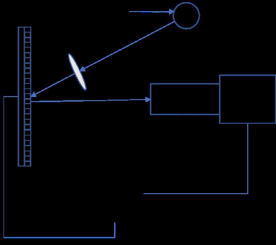
In this section,we will describe parallel optical FPA,two-cascade imaging,and GPU-adaptive reconstruction architecture. In the low-resolution image acquisition phase and high-resolution image estimation phase,the light reflected by an object is imaged by an objective lens and modulated on the DMD,and then reimaged on the detector FPAs by a projection image lens;finally,the high-resolution image is recovered from the acquired low-resolution image by real-time parallel programming on the GPU.
In this section,we describe the BCS imaging architecture shown in
![]()
Figure 1.Block compressed sensing(BCS)architecture with a graphics processing unit(GPU)acceleration imaging system
In the experimental optical setup,the light source was a View Solutions halogen lamp. We utilized a Texas Instruments digital micromirror device(TI DMD)as the SLM. The DMD contained 1024 × 768 micromirrors,each mirror of size 13.68 × 13.68 µm. Each mirror could be independently rotated to either +12° or -12° position. We used an objective lens with a focal length of 50 mm to focus the light onto the DMD. We used a 1388 × 1038 sensor(ALLIED Vision Technologies Manta G-145)with a pixel size of 6.45 × 6.45 µm connected to an image lens with a focal length of 30 mm to validate the proposed method,which is the same to procedures in the medium and long infrared wave spectrum. The sensor and image lens faced the DMD and could be rotated around the optical axis,so as to align the relative position of the sensor and DMD as accurately as possible.
In this paper,the compression ratio scale of
1.2 Image system model for BCS measurement
In an SPC,the observation value vectors of all pixel intensities
The FPA functions parallel to the measuring image system,which employs a focal plane array detector instead of the single pixel detector of the SPC via image plane coding and provides a flexible optical architecture and multiplex simultaneous information acquisition method using FPA pixels measurement of the inner product of modulation function multiplied with the image. Consequently,the original image is compressed and recorded on the low-resolution sensor. The compression ratio is equal to the mapping of the signal from mask elements to a single pixel element of sensor by
where
Let
Eventually,one measurement of the complementary matrices is given as
where
1.3 Performance of under-sampling reconstruction: Inversing versus CS
The use of an orthogonal gray matrix results in a long sampling time,and fails to obtain images fast. Although a relatively high reconstruction speed can be achieved by inverse transformation,the full sampling is inevitable;otherwise,the quality of under-sampling will be very poor or the full sampling will increase the sampling time. In the proposed optical architecture,DMD functions as the SLM to achieve 0/1 modulation on the gray image. The advantage of the +1/-1 Hadamard matrix is that it is easy to realize and provides notable imaging speed;hence,the Hadamard matrix was chosen as the modulating function
![]()
Figure 2.Inverse(a,c,e)and CS(b,d,f)reconstruction results with subsampling rate = 0.3,the image sizes are(a),(b)32 × 32 pixels,(c),(d)64 × 64 pixels,and(e),(f)128 × 128 pixels
where x represents position in the image,
Also,to evaluate the reconstruction accuracy of the proposed method,the PSNR between the original and reconstructed images was adopted as a performance indicator:
where
1.4 MBCS measurement matrix and projection vectors
This section describes the construction method of the measurement matrix and projection vector for a configurable compression ratio scale of
![]()
Figure 3.Unit of projection vectors derived from a compressive element block. A part of the coding pattern on the SLM is divided into four identical parallelly measuring blocks. One measurement entry,which corresponds to a measurement operation and an observed value,is reshaped into a vector according to the vertical orientation
First,the image is divided into several element blocks
The observed value vectors of all partitioned blocks are synchronized with each projection vector in the well-designed measurement matrix. First,the parallel blocks in the observed results are successively arranged in a column-wise manner. Second,column vector of the observed value for each block originates from the corresponding linear combination of blocks in the measurement sequence. Therefore,each low-resolution image consists of the projection results of all element blocks,while the observed vector in each block consists of the observed values of specific blocks distributed over the corresponding position of every low-resolution image. The measurement matrix is depicted schematically in
![]()
Figure 4.
1.5 Evaluation of reconstruction performance related to the block size
We simulated the under-sampling imaging process with the image size of 128 × 128 pixels. The compression rate was 8 × 8,and the under-sampling rates were 0.8125,0.6875 and 0.5. The construction of the measurement matrix and the observed values for different block sizes refer to the method described in section 1.4.
![]()
Figure 5.Peak signal-to-noise ratio(PSNR)and reconstruction time with different block sizes and different under-sampling rates
The MBCS reconstruction results are expected to be better than those of single-block reconstruction,which is the case of a block size of 1. This is because multi-blocks reconstruction is expected to preserve more edge information and continuity information between the blocks comparing with a single block;furthermore,MBCS improves the overall sparsity of the measurement matrix. In addition,when the overall reconstruction is divided into many small parts to be rebuilt separately,more time is spent on variables and algorithm initialization. Initially,as the block size of the reconstruction increases,the speed increases. Later,as the size increases further,the computational cost of each block reconstruction increases rapidly,and the overall reconstruction time starts increasing. These regularities motivate the design of block-compressive sensing reconstruction.
1.6 MBCS reconstruction strategy with GPU acceleration
The GPU is a computing device capable of executing many identical programs simultaneously and processing different data with a large number of threads in parallel[
The CS reconstruction procedure can be improved using the high-performance computing characteristics of the GPU and parallel image acquisition on FPA. According to related research results,the traditional CS reconstruction algorithm(for instance,Total Variation,TV)spends time mainly on matrix operations in each iteration of TV optimization,such as linear and multiplication operations. This seriously affects the performance. Hence,the GPU can be used to reduce time cost and improve recovery speed drastically. In addition,it is important to minimize the data transmission overhead cost between the host and device. To efficiently exploit and utilize the performance of the GPU for matrix manipulation,several strategies were proposed:(a)Implementing sparse matrix multiplication and sparse matrix-vector multiplication based on cuSparse library to accelerate procedure;(b)Storing and loading the matrix in a sparse format used for sparse matrix multiplication operation,which can effectively improve GPU performance;(c)When rebuilding blocks sequentially,avoiding reloading the measurement matrix into the GPU global memory from an external storage,and using a consistent measurement matrix derived from the same patterns for each block;(d)Alternating the measurement matrix size derived from the FPA coding scale and the optimal partitioning block size described in the previous sections depending on the problem size and equipment characteristics(such as scene size and computer performance);and(e)Merging several frames together into one frame to reconstruct.
![]()
Figure 6.Block-compressive reconstruction procedure with GPU acceleration
(1)Prepare a blocked projection matrix on the GPU referring to the method described in section 1.4. Generate a full blocking projection matrix with dimensions
(2)Prepare the block observed values on GPU by the method described in section 1.4. To achieve a higher reconstruction efficiency,corresponding low-resolution observed values should be loaded into the host,and multiframes should be merged into one frame
(3)Reconstruct each block with the acceleration GPU functions and stitch all reconstructed high-resolution blocks into a high-resolution overall frame. In this step,the matrix structure definitions in the Compressed Sparse Column format on CUDA device and host and GPU kernel functions related to linear operation and matrix-vector multiplication are used.
2 Experiment and results
2.1 Experiment configuration
The experiment optical setup described in section 1.2 is the optical prototype architecture. The reconstruction system is equipped with Intel Core i7-9700K 3.60 GHz ×8,GeForce RTX 2080Ti(4352 computational cores;clock frequencies are 1350–1635 MHz;11 GB GDDR;352 bit bandwidth;access rate is 14 GB/s;and throughout rate is 616 GB/s). The operating system is Ubuntu 18.04.2 LTS 64 bit. The object scenes of the experiment are as follows:(a)A digital chart[
2.2 Low-resolution acquisition result and high-resolution reconstruction quality
According to the experimental reconstruction results,high-resolution imaging can be achieved with low-cost and low-resolution sensors. Furthermore,sampling data transmission only needs very low bandwidth,and this helps to improve the frame rate of high-resolution imaging.
![]()
Figure 7.Comparison of experimental results from different low-resolution images with different compression ratios[
| Image Type | Compression Ratio | Traditional Block CS | MBCS | ||
|---|---|---|---|---|---|
| PSNR | FSIM | PSNR | FSIM | ||
| Digital Chart | 2x2 | 12.99 | 0.54 | 15.63 | 0.85 |
| 4x4 | 12.67 | 0.76 | 14.74 | 0.84 | |
| 8x8 | 16.45 | 0.79 | 16.7 | 0.81 | |
| Film | 2x2 | 20.23 | 0.92 | 33.89 | 0.99 |
| 4x4 | 24.85 | 0.93 | 29.4 | 0.96 | |
| 8x8 | 18.09 | 0.89 | 23.26 | 0.91 | |
| Toy | 2x2 | 16.77 | 0.61 | 40.31 | 0.99 |
| 4x4 | 30.44 | 0.94 | 37.48 | 0.97 | |
| 8x8 | 34.55 | 0.95 | 35.01 | 0.97 | |
Table 1. Comparison of the quality between traditional Block CS and MBCS
2.3 MBCS reconstruction with GPU acceleration
We compared the reconstruction time implemented on the GPU with the reconstruction algorithm implementation on the CPU. We performed a simulation to recover 32 × 32,64 × 64,and 128 × 128 pixel head phantoms[
| Image Size | CPU-Matlab | GPU | Speedup |
|---|---|---|---|
| 32×32 | 0.39s | 0.05 s | 7.79 |
| 64×64 | 7.86s | 0.03 s | 216 |
| 128×128 | 38.12s | 0.140 7 s | 270 |
Table 2. Comparison of the reconstruction time between Matlab–CPU and GPU
Then,the MBCS reconstruction algorithm with GPU acceleration was applied to the experimentally acquired images from the optical architecture described herein. The results show the outstanding performance of the MBCS algorithm on GPU. A larger block has more efficient reconstruction performance,thereby verifying the effectiveness of the GPU acceleration strategy described in section 1.5.
In the experiment,first,we attempted to reconstruct the high-resolution image with a size of 128 × 128 pixels from the acquired low-resolution images with a size of 64 × 64 pixels at a compression ratio of 2 × 2. Then,multiple 64 × 64 pixels low-resolution images were manually stitched into 128 × 128 pixels and 256 × 256 pixels by using 4 and 16 low-resolution images to reconstruct high-resolution images of sizes 256 × 256 and 512 × 512 pixels,respectively. Thus,multiple captured low-resolution frames can be stitched into a new large one. That is equivalent to reconstructing multiple images rapidly and simultaneously to further increase the frame frequency of reconstruction.
| HR img Size | Blk Size | Blks Cnt | CPU(s) | GPU(s) | AVG/blk(s/blk) |
|---|---|---|---|---|---|
| 128×128 | 2×2 | 4096 | 5.54 | 261.421 | 0.0638 |
| 4×4 | 1024 | 1.38 | 47.4067 | 0.0462 | |
| 8×8 | 256 | 0.73 | 9.91136 | 0.0387 | |
| 16×16 | 64 | 2.59 | 2.4248 | 0.0378 | |
| 32×32 | 16 | 1.92 | 0.6156 | 0.0384 | |
| 64×64 | 4 | 21.02 | 0.1555 | 0.0388 | |
| 256×256 | 2×2 | 16384 | 553 | 642.82 | 0.0392 |
| 4×4 | 4096 | 113 | 158.72 | 0.0387 | |
| 8×8 | 1024 | 48.17 | 39.4221 | 0.0384 | |
| 16×16 | 256 | 13.66 | 9.5957 | 0.0374 | |
| 32×32 | 64 | 8.76 | 2.3923 | 0.0373 | |
| 64×64 | 16 | 38.25 | 0.6047 | 0.0377 | |
| 128×128 | 4 | 119.92 | 0.1617 | 0.0404 | |
| 512×512 | 2×2 | 65536 | 998.98 | 2604.89 | 0.0397 |
| 4×4 | 16384 | 282.13 | 636.393 | 0.0388 | |
| 8×8 | 4096 | 102.49 | 158.697 | 0.0387 | |
| 16×16 | 1024 | 55.42 | 38.346 | 0.0374 | |
| 32×32 | 256 | 45.13 | 9.6851 | 0.0378 | |
| 64×64 | 64 | 106.64 | 2.4376 | 0.0380 | |
| 128×128 | 16 | 125.16 | 0.6357 | 0.0397 | |
| 256×256 | 4 | 71.35 | 0.2239 | 0.0559 |
Table 3. Comparsion of MBCS reconstruction times between the CPU algorithm and GPU acceleration for 128 × 128, 256 × 256, and 512 × 512 scenes. The first column lists the size of high-resolution images, HR stands for high resolution. The second column is the block size used to reconstruction, the third column shows the number of blocks in block reconstruction, the fourth column lists the time to recover one HR image in Matlab, the fifth column lists the time to recover one HR image by the MBCS algorithm with GPU acceleration, the sixth column lists the average time to recover each block of HR image, and it is equal to corresponding value in column “GPU (s)” divided by the corresponding value in column “Blks Cnt”
First,the experiment results shown in
![]()
Figure 8.Reconstruction time for the 128 × 128 scene by the MBCS algorithm using CPU and with GPU acceleration for different block sizes
![]()
Figure 9.Reconstruction time for the 256 × 256 scene by the MBCS algorithm using CPU and with GPU acceleration for different block sizes
![]()
Figure 10.Reconstruction time for the 512 × 512 scene by the MBCS algorithm using CPU and with GPU acceleration for different block sizes
Second,the average time for single-block reconstruction with different image sizes using the MBCS algorithm with GPU acceleration is very close in the experiment according to the data in “AVG/blk(s/blk)” column in
3 Conclusion
We proposed an optical parallel image prototype system based on the FPA CI system combined with the MBCS algorithm,which can be used low-cost and low-resolution infrared sensors to perform real-time imaging and display of short and medium infrared spectrum. And through theoretical analysis and the visible optical imaging experiments,the effectiveness and practicability of the proposed MBCS method were verified. We also discussed the MBCS measurement matrix of the reconstruction model and under-sampling feature of CS for fast imaging in the highly parallel CI system. The reconstruction performances related to the block size,merging multi-images into a single image and MBCS reconstruction strategy with GPU acceleration were analyzed. In the experiment,we used the Hadamard matrix entries as the modulation pattern for parallel image acquisition and successfully achieved high-resolution scene imaging using a low-resolution sensor. It proved that the MBCS can effectively improve the reconstructed image quality greater than the traditional method,meanwhile there is an optimal block size to achieve fast reconstructing and high imaging quality. Depending on the GPU-based prototype and architecture,both the low-resolution image acquisition and high-resolution image reconstruction were achieved simultaneously in real-time.
In the optical experiment,the maximum compression ratio 8×8 was carried out. The imaging resolution can be increased by 64 times,but it is not the upper limit. The system can well solve the inadequate resolution problem of the detector in infrared imaging,or even THz and other fields. The frame performance of 5Hz can satisfy the requirements of a great many fast imaging scenes. In future work,we will explore more optimization strategies,such as the use of multiple GPU devices,and try more efficient modulation matrix and reconstruction algorithms to reduce data transfer expenditure between the CPU host and the GPU device. We are also studying three-dimensional imaging and an embedded arm signal processors with a high-performance architecture.
References
[1] D L Donoho. Compressed sensing. IEEE Transactions on Information Theory, 52, 1289-1306(2006).
[2] E J Candès, J Emmanuel. Compressive sampling. in: Proceedings of the International Congress of Mathematicians, 3, 1433-1452(2006).
[8] C V Trinh, K Q Dinh. Edge-preserving block compressive sensing with projected landweber(2013).
[13] J E Fowler, S Mun, E W Tramel. Block-based compressed sensing of images and video. Foundations and Trends in Signal Processing, 4, 297-416(2012).
[17] Y Chen, S Liu, X R Yao et al. Discrete cosine single-pixel microscopic compressive imaging via fast binary modulation. Optics Communications, 454, 124512(2012).
[22] K Jain Anil. Fundamentals of digital image processing. Englewood Cliffs, NJ, Prentice-Hall, 439(1989).


Set citation alerts for the article
Please enter your email address

© Copyright 2018-2021 | Chinese Laser Press. All Rights Reserved 沪ICP备15018463号-20