
Xiao SHAO, Rui-Heng LIU, Liang WANG, Jing CHU, Guang-Hui BAI, Sheng-Qiang BAI, Ming GU, Li-Na ZHANG, Wei MA, Li-Dong CHEN. Interfacial Stress Analysis on Skutterudite-based Thermoelectric Joints under Service Conditions [J]. Journal of Inorganic Materials, 2020, 35(2): 224
- Journal of Inorganic Materials
- Vol. 35, Issue 2, 224 (2020)
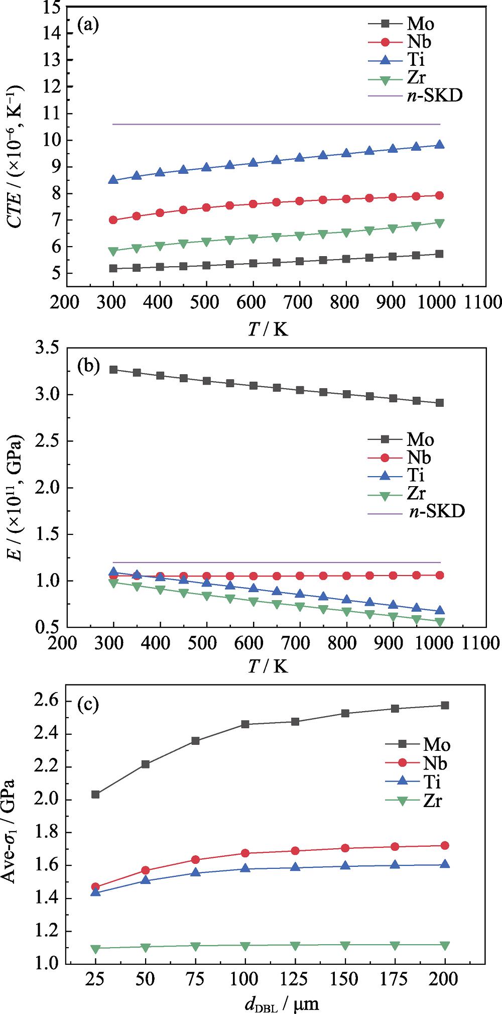
. (a) CTE , (b) Young’s modulus (E ), and (c) variations of average first principle stresses with thicknesses of different DBL candidates (purple lines: CTE and E of SKD)
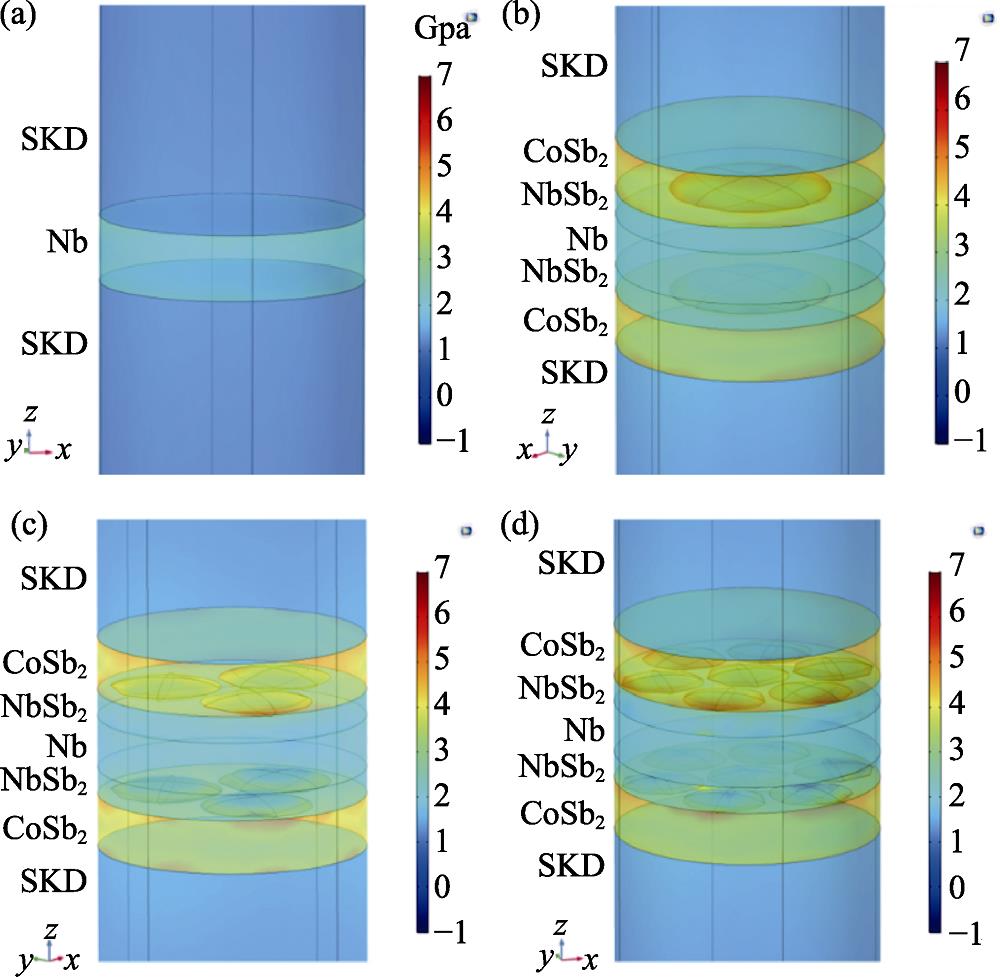
. σ 1 distributions for (a) n =0, (b) n =1, (c) n =3, and (d) n =7 (initial thickness of Nb: 25 μm)
. Variations of average σ 1 on each interface with thicknesses of NbSb2 and Nb
. EDS mappings of (a, d) interfaces and (b, e) fracture surfaces of (a-b) unaged joint and (d-e) sample 650-10d (White line indicating the fracture surface, and white arrow indicating direction of observation in (b) or (d)); Total element data were shown in table (c) for figure (b) and in table (f) for figure (e)
. (a) Finite element model of SKD/Nb joint with pores, detailed meshes of (b) NbSb2 layer and (c) CoSb2 layer
. Interface structures and line scans of joints
. Relationships between interface stresses and pores major axis ratios
. (a) Calculated stress state of SKD/Zr joint with the Zr layer of 25 μm and the micropores number n of 3; (b) Variation of average σ 1 on SKD/CoSb2 interface with thickness of ZrSb2 and Zr (n =3); (c) Variation of average σ 1 on CoSb2/ZrSb2 interface with thickness of ZrSb2 and Zr (n =3); (d) Variation of average σ 1 on ZrSb2/Zr interface with thickness of ZrSb2 and Zr (n =3)
|
Table 1.
Basic properties including molar mass, density, Young’s modulus, Poisson’s ratio, thermal conductivity, thermal expansions and heat capacity for series of materials
|
Table 1.
Relative volume changes for one interface (SKD/Nb and SKD/Zr joints)
|
Table 2.
Thicknesses of NbSb2 layer dNbSb2, average sizes of micropores c, tensile strengths σt, maximum calculated stresses Ave-σ1 and the location interfaces, compositions of tensile fracture surface for series of aging SKD/Nb joints。。

Set citation alerts for the article
Please enter your email address
© Copyright 2018-2021 | Chinese Laser Press. All Rights Reserved 沪ICP备15018463号-20