• Journal of Semiconductors
  • Vol. 42, Issue 4, 041306 (2021)
Jianou Huang1, Chao Li1, Rongguo Lu2, Lianyan Li3, and Zizheng Cao1
Author Affiliations
  • 1Eindhoven University of Technology, Eindhoven 5600MB, The Netherlands
  • 2State Key Laboratory of Electronic Thin Films and Integrated Devices, School of Optoelectronic Science and Engineering, University of Electronic Science & Technology of China, Chengdu 610054, China
  • 3College of Electronic and Optical Engineering & College of Microelectronics, Nanjing University of Posts and Telecommunications, Nanjing 210046, China
  • show less
    DOI: 10.1088/1674-4926/42/4/041306 Cite this Article
    Jianou Huang, Chao Li, Rongguo Lu, Lianyan Li, Zizheng Cao. Beyond the 100 Gbaud directly modulated laser for short reach applications[J]. Journal of Semiconductors, 2021, 42(4): 041306 Copy Citation Text show less

    Abstract

    It is very attractive to apply a directly modulated laser (DML)-based intensity-modulation and direct-detection (IM/DD) system in future data centers and 5G fronthaul networks due to the advantages of low cost, low system complexity, and high energy efficiency, which perfectly match the application scenarios of the data centers and 5G fronthaul networks, in which a large number of high-speed optical interconnections are needed. However, as the data traffic in the data centers and 5G fronthaul networks continues to grow exponentially, the future requirements for data rates beyond 100 Gbaud are challenging the existing DML-based IM/DD system, and the main bottleneck is the modulation bandwidth of the DML. In this paper, the data rate demands and technical standards of the data centers and 5G fronthaul networks are reviewed in detail. With the modulation bandwidth requirements, the technical routes and achievements of recent DMLs are reviewed and discussed. In this way, the prospects, challenges, and future development of DMLs in the applications of future data centers and 5G fronthaul networks are comprehensively explored.

    1. Introduction

    Optical fiber communication has the advantages of large capacity, high quality, stable performance, anti-electromagnetic interference, and strong confidentiality[1]. It is a long-term solution for the development of broadband access. In recent years, with the emergence of new services and devices such as smart handheld terminal devices, ultra-high-definition video TVs, big data storage, cloud computing, and virtual reality, the research on optical access networks has evolved from the 100 Mb/s capacity stage to the hundreds of Gb/s capacity stage. So far, there has been a continuous demand to upgrade the optical fiber network to 100/200 Gb/s, and soon, a 400 Gb/s data rate using a digital coherent transceiver on the line sides will be provided according to the requirements of long-distance and metropolitan area networks[2, 3]. Coupled with 5G services' related requirements for access networks, this type of upgrade promotes the data rate to support 400 Gb/s capacity and higher rates to match the line side transponder speed. Fig. 1 shows a typical fiber-optic communication network for the core/metro and access network scenarios[4]. Currently, digital coherent optical communication and intensity-modulation and direct-detection (IM/DD) solutions are mainly applied to metropolitan area networks and access networks, respectively.

    (Color online) A typical fiber-optic communication network for the core, metro and access network scenarios, where the IM/DD links are addressed in the metroedge and intra-/inter-data center networks. CO: center office; RN: remote node; DCI: datacenter interconnects. © [2020] IEEE. Reprinted, with permission, from Ref. [4].

    Figure 1.(Color online) A typical fiber-optic communication network for the core, metro and access network scenarios, where the IM/DD links are addressed in the metroedge and intra-/inter-data center networks. CO: center office; RN: remote node; DCI: datacenter interconnects. © [2020] IEEE. Reprinted, with permission, from Ref. [4].

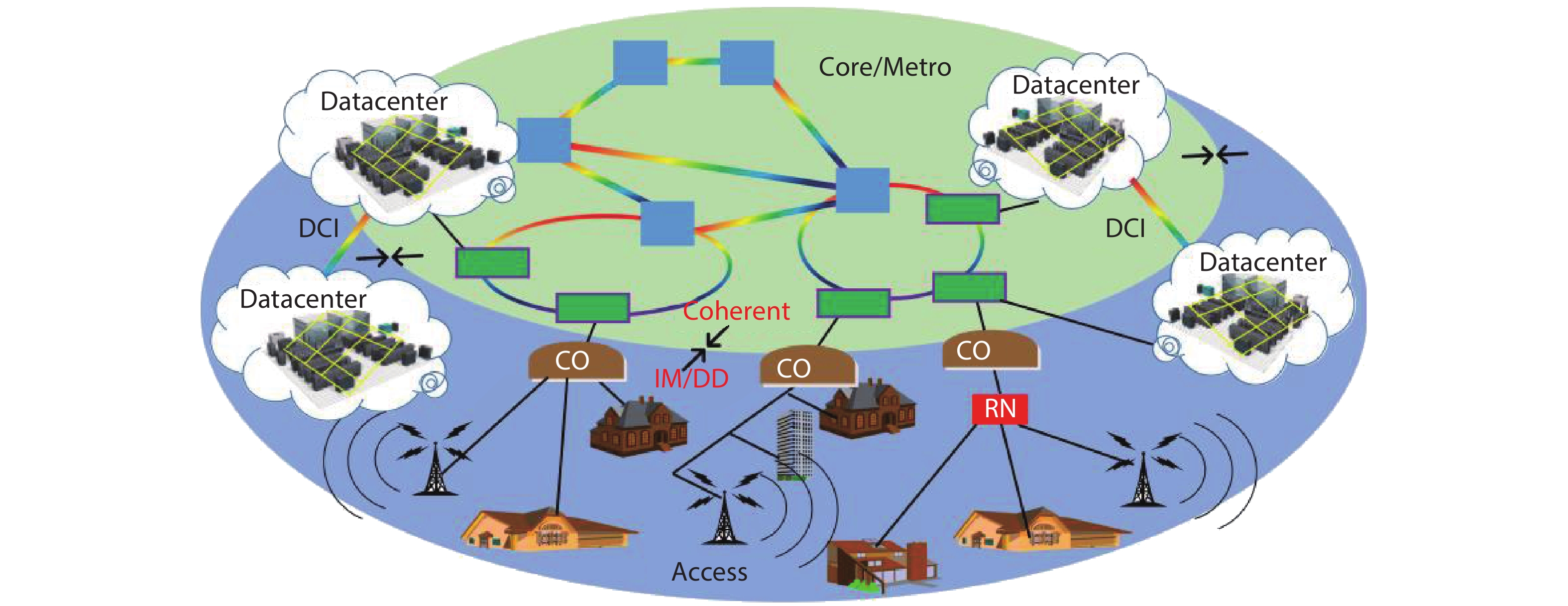
    In addition to this continuous development of traditional telecommunications networks, content providers have recently promoted higher requirements for optical interfaces with higher data rates, usually in the form of data centers with their own network infrastructure as shown in Fig. 1. Nowadays, due to the storage, transmission and processing of large amounts of data, the traffic in the data center will greatly increase[5]. These high-speed data links can be divided into two groups: intra-data center and inter-data center links. The first group includes short-distance data links ranging from a few meters to a few kilometers, connecting servers and racks in the data center. The second group is also commonly referred to as the data center interconnect (DCI), which enables data exchange between multiple data centers to be much longer than the links within the data center, usually ranging from several kilometers to hundreds of kilometers[6]. Researchers have established various industry standards and multi-source protocol groups to propose transceiver specifications for these application scenarios. For example, regarding the supported distance, the 100G Ethernet transceiver standard can be classified as a short range (SR) (100 m), data-center range (DR) (500 m), fiber reach distance (FR) (2 km), long reach distance (LR) (10 km), and extended distance (ER) (40 km). In the upcoming 400G era, IM/DD solutions still give priority to these specifications due to cost, power consumption, and occupying advantages[7, 8].

    Moreover, with the continuous development and maturity of 5G technology, the mobile fronthaul network based on the optical access network has also received extensive attention from academia and industry[9]. Therefore, the future optical access network not only needs to satisfy the traditional fixed network access service, but also needs to meet the mobile access service requirement, which puts forward new demands on the capacity of the optical access network. The increase in the capacity of the optical access network will inevitably bring great challenges to the operator's laying cost since the optical access network is very cost-sensitive. The low-cost technologies have always been the main research topic of the optical access network. IM/DD technology, as the mainstream transmission technology of optical access network, has been widely studied and applied in recent years. A typical IM/DD system with digital signal processing (DSP) and advanced modulation formats based on a directly modulated laser (DML) is illustrated in Fig. 2. The configuration of such a system is simple, leading to the advantages of low cost, low power consumption, small size, and convenience to integrate in the optical module.

    (Color online) A schematic diagram of the IM/DD system based on DML. DSP: digital signal processing; DAC: digital-to-analog convertor; LDD: laser diode driver; DML: directly modulated laser; SMF: single mode fiber; MMF: multi-mode fiber; ADC: analog-to-digital convertor.

    Figure 2.(Color online) A schematic diagram of the IM/DD system based on DML. DSP: digital signal processing; DAC: digital-to-analog convertor; LDD: laser diode driver; DML: directly modulated laser; SMF: single mode fiber; MMF: multi-mode fiber; ADC: analog-to-digital convertor.

    The semiconductor laser is one of the most important components in the IM/DD system. It determines the achievable data rate of the system from the bottom. Thus, long-term efforts have been made in semiconductor laser research in order to obtain broad bandwidth, low noise, and high power efficiency, so that it meets the increasing demand of the transmission data rate[10, 11]. In an IM/DD system, the semiconductor laser is usually used as the coherent light source of the modulator, or as the modulator directly. The former case corresponds to the external modulation method, and the latter case corresponds to the direct modulation method. They are the two main approaches to modulate the electrical signal on the optical carrier. In the external modulation method, the optical carrier generated from the laser source is modulated by a separate modulator (such as electro-absorption modulator and electro-optic modulator) under the driven of the electronic signal. This approach has the advantages of larger bandwidth and reduced chirp. However, the need of the separate modulator leads to high cost and low integration. Therefore, the external modulation is widely used in the long-distance optical trunk transmission (> 10 km)[12]. While in the direct modulation method, the modulated optical signal can be obtained by directly modulating the laser current with the electronic signal, resulting in lower cost and lower system complexity. Thus, the direct modulation approach is very suitable for short-distance (within tens of kilometers) high-speed transmission between a large number of devices, which is exactly the situation in data centers and 5G fronthaul network. However, the relatively narrow bandwidth and the frequency chirping of the DML limit the performance of the direct modulation approach[13]. Nevertheless, for transmission distance within tens of kilometers, the direct modulation still can provide good performance[14].

    The most commonly used three types of DMLs are the Fabry–Perot (FP) laser, the vertical cavity surface emitting laser (VCSEL), and the distributed feedback (DFB) laser. For the low-cost VCSEL, due to its multi-transverse-mode operation, the transmission distance is limited by the modal dispersion, and is usually tens of meters. On the other hand, due to its short cavity length, the modulation bandwidth of the VCSEL can achieve up to 30 GHz[15]. Thus, the VCSEL is widely used in short-range high-speed applications, such as internal data centers. For the FP laser, due to its multi-longitudinal-mode operation, the transmission distance is limited by the chromatic dispersion, and is usually hundreds of meters. Therefore, the FP laser is generally used in an optical access network with a modulation bandwidth of several GHz. As for the single mode DFB laser, the transmission distance is only limited by its optical output power level and chirp-related dispersion. Transmission distance up to tens of kilometers can be achieved. Moreover, the modulation bandwidth of the DFB laser can achieve up to tens of GHz. Therefore, the DFB laser is the superior choice of the DML of the IM/DD system used in data centers and 5G fronthaul network.

    Based on the previous discussion, it is very attractive to apply DML-based IM/DD system in data centers and 5G fronthaul network due to its advantages of low cost, low system complexity, and high energy efficiency, which perfectly match the application scenarios of data centers and 5G fronthaul network, in which a large number of high-speed optical interconnections are needed. However, the future demand of high data rate in data centers and 5G fronthaul network is challenging the existing DML-based IM/DD system, and the main bottleneck is the modulation bandwidth of the DML. Therefore, it is necessary to explore the prospects, challenges, and future development of DMLs in the applications of future data centers and 5G fronthaul network. In this paper, this topic is comprehensively discussed. We narrow our focus on the DFB DMLs and DFB-based advanced DMLs, because their transmission distance is guaranteed by the single-mode operation and they have huge potential to achieve broader modulation bandwidth. In Section 2, the data rate demands and technical standards of data centers and 5G fronthaul networks are reviewed in detail. And the modulation bandwidth requirements of the DML are included. In Section 3, the technical routes and achievements of recent DMLs are reviewed and discussed based on the rate equation theory model. In Section 4, the prospect of applying DMLs in the future data centers and 5G fronthaul networks is discussed in terms of feasibility, technical complexity and future improvement direction.

    2. Industry requirements and standards for data centers and 5G networks

    For a long time, components used for photoelectric conversion and electro-optical conversion (especially DMLs) have been the bottleneck of the end-to-end channel bandwidth in high-speed IM/DD systems. This is mainly due to the following facts: fundamentally speaking, the design, manufacturing and packaging process of such optoelectronic components and devices that support a wide bandwidth while maintaining low noise levels are challenging. Technological advancements in different fields, including material technology, design, manufacturing and packaging are strictly required. Recently, a significant progress has been made in the design and manufacture of such broadband components to greatly enhance the channel capacity of the IM/DD system[16, 17]. A DML with more than 70-GHz modulation bandwidth is expected to realize a 200 Gb/s per channel IM/DD transmission to meet the requirement of data centers and 5G networks. The specific requirements and some international standards are summarized and presented in this section.

    2.1. Data center

    As the core platform for the cloud computing, the need to develop data centers is becoming more and more urgent. The current data centers are far from being able to meet the needs of today's society in terms of quantity and performance. Most big data processing and calculations are carried out in data centers. According to the Cisco Global Cloud Computing Index White Paper, 99% of global communication traffic is related to data centers. Among them, most data communications are still concentrated inside the data center. Due to the explosion of data volume and the rapid growth of network traffic, data centers are upgrading from 10G/40G to 25G/100G/400G architectures. Traditional electrical interconnection is difficult to meet the increasing transmission bandwidth and transmission rate requirements of data centers, which brings huge opportunities for optical interconnection. Optical transmission has the advantages of large bandwidth and long-distance transmission. Its main application scenario is to provide a large-bandwidth information transmission channel between the two points. The use of optical interconnection between data centers and within data centers will greatly enhance the data processing and computing capabilities of the data centers. In today's data center network, almost every connection uses optical interconnection technology, including the connection between servers and switches within a few meters of the data center. And simply the growth of the data traffic in the data center does not really benefit the internet of things. Only when numerous data centers are interconnected can it be possible to benefit data transmission under the internet of things. Scalable data center architecture meets the growth of east–west traffic in modern ultra-large-scale data center architecture, making data center interconnection possible. A large amount of data traffic will use optical transmission to enter the data center, and information cloud data is shared between data centers, so that optical transmission will be used not only for data transmission within the data center, but also for interconnection between data centers. Therefore, the scale of optical transmission in the data center optical interconnection market will far exceed that of telecom operators.

    For the internal interconnection of the data center, the most ideal method is that each server is connected to all other servers, so that the application layer software does not need to communicate with the central computer responsible for computing task scheduling. However, such a network structure will be extremely complex and costly. In practice, the data center adopts a topological hierarchical structure, and the interconnection between clusters is converged through a packet switching network. Parallel optical transmission technology is an important method of the data center internal communication. This transmission method can not only greatly increase the communication rate, but also combines the parallel data channel structure in the large-scale network architecture, and the data processing speed is also greatly improved. The short-distance optical connection usually uses a DML with low cost, low power consumption, and enough modulation bandwidth. In order to achieve higher transmission rates and reduce the transmission cost per bit, the application of optical integrated circuits (PIC) and wavelength division multiplexing (WDM) technologies has gradually become the mainstream.

    As a key factor in the data center, optical modules have broad development prospects. The interconnection of 40G to 100G is imminent. Generally speaking, a short-distance 100 Gb/s optical interconnection can use Gb/s parallel channels as shown in Table 1. In addition to performance and cost, space size, service life, and compatibility with future technologies are all very important aspects. At the same time, the formulation of standards for over 100G is in full swing, and some feasible solutions are also proposed. To ensure that these solutions can meet the cost and power requirements of future data centers, more new optical module concepts are necessary. Currently, the cost of manufacturing optical modules, packaging costs and optoelectronic chip costs account for 80% to 90% of the entire optical module. The use of open optical modules can greatly reduce costs. On the other hand, turning the optical module into an independent component that is not bundled with the system equipment allows data center customers to choose an interconnection scheme that is most suitable for them. It is conducive to finding optical module manufacturers for customized features and realizing targeted operation and maintenance management. With the next generation of 100G and 400G networks, the realization of high-speed signals has become increasingly difficult. Generally speaking, there are two ways to increase bandwidth in fiber links: the first is to increase the bit rate of each channel, and the second is to increase the number of channels. There are two ways to increase the bit rate: the first is to directly increase the baud rate; the second is to keep the baud rate unchanged and use a higher order modulation and coding format. The next Ethernet rate after 100 Gb/s is likely to be 400 Gb/s. IEEE 802.3 launched the 400 Gb/s Ethernet research group in 2014 to define the 400 Gb/s Ethernet standard. Table 1 shows the main task force of high-speed (>50 Gb/s) IEEE standard. The solution to 400G is generally divided into four generations. The 1st generation has products that are packaged in optical modules such as the low power alliance interface 8 (CPF8). The electric signal adopts 16 × 25G, and the optical signal adopts the FR8 and L8 schemes of G and G. The 2nd generation electrical signal rate is upgraded to 50G, using eight channels. Optical signal transmission adopts FR8 and LOR8 schemes of single-mode fiber, and the speed of electrical signal and light are fully matched. The 3rd generation electrical signal is still 50G, and the light can be upgraded to 100G. The 4th generation has been upgraded from electricity to light to a single channel of 100G. In order to achieve a single-channel 400G or higher rate, coherent detection technology will have a wide range of application requirements. At present, the Optical Internet Forum (OIF) has begun to establish a project to study this standard and named it as 400 ZR. It is expected that this project could soon become a standard.

    Table Infomation Is Not Enable

    To meet the ever-increasing bandwidth requirements of data centers, data rates, device power consumption, and space density need to be increased on a large scale. In the next few years, the speed of optical transceivers in data centers will increase by 4 times, while power consumption and space occupation will remain unchanged. The traditional binary on–off keying (OOK) modulation method can reach a rate of 20 Gb/s or more in an IM/DD system. In order to achieve a higher rate of transmission, it is necessary to put forward higher requirements on the bandwidth and dispersion performance of optoelectronic devices, and at the same time new technologies are required to be applied to short-distance optical connections. These new technologies include dispersion compensation, low-power integrated silicon optical circuits, and the evolution of new DML array to build parallel multi-channel. Parallel channel technology includes multi-fiber technology and multi-wavelength technology. At the transmitting end, the electrical signal passes through the drive circuit to modulate the laser array to generate parallel multi-path optical signals, and then these optical signals are coupled into the optical fiber for transmission. At the receiving end, the optical signal is converted into an electrical signal by the photodetector array, and then the electrical signal is recovered by the receiver circuit.

    2.2. 5G fronthaul

    The 5G radio access network (RAN) mainly adopts the small-scale centralized mode of the gNB macro station, the centralized unit (CU), and the distributed unit (DU) in the early stage. In the future mature period, the CU and the DU separation mode can be adopted and CU cloudification and CRAN centralized construction mode can be implemeted. For the small-scale centralized scenario of CRAN, the DU is mainly deployed in the access computer room, and the centralized scales of base stations are usually from 3 to 5, which are connected to the nearest secondary optical switch or directly connected to the ODF of the base station computer room, no need to cross the backbone optical ring. For the large-scale centralized scenario of CRAN, the DU is deployed in a common convergent computer room or integrated service access site. The centralized scale is usually 10–20 base stations and it crosses the backbone optical ring.

    As an industrial cooperation organization, the Common Public Radio Interface (CPRI) Alliance defines publicly available specifications for the internal interface of the 5G fronthaul network between Radio Equipment (RE) and Radio Equipment Control (REC)[18]. After CPRI released the latest version of CPRI V7.0 in October 2015, it is committed to promoting the definition of a new enhanced CPRI specification, named eCPRI. Then the latest version of the eCPRI specification V2.0 is released in May 2019. This specification defines the fronthaul interface of the Ethernet format. Compared with the traditional CPRI interface, the bandwidth of eCPRI is reduced by 10 times under the same conditions, and it also realizes the adaptation between the bandwidth of the fronthaul network and the load from the base station[19].

    The 5G fronthaul mainly realizes signal transmission between active antenna unit (AAU) and DU. The technical solutions mainly include optical fiber direct connection and WDM solutions. WDM solutions can be divided into passive, active, and semi-active. The main technical characteristics are as follows:

    (1) Optical fiber direct connection scheme: the AAU and DU are directly connected by optical fiber. AAU and building baseband unit (BBU) are equipped with 25 Gb/s white light modules. Generally, a single 5G S111 base station requires 6-core fiber resources when using dual-fiber bidirectional interconnection. Considering that the large-scale construction of 5G base stations will consume huge access layer fiber resources, the industry proposes a 25 Gb/s BiDi (bidirectional) solution. The data signals in both directions of AAU and DU are transmitted in one fiber using different wavelengths. It can save half of the fiber resources by reducing from six cores to three cores.

    (2) Passive WDM solution: It means that both the AAU and DU are equipped with color light modules, and a passive multiplexer/demultiplexer is deployed at both ends to realize color light channel signal multiplexing without any active transmission equipment. This solution only needs one core optical fiber cable when it is based on single-fiber bidirectional mode in unprotected scenarios. Currently, the main commercial products of passive WDM solutions are based on fixed wavelength coarse wavelength division multiplexing (CWDM) solutions.

    (3) Semi-active WDM solution: Deploy active WDM equipment on the DU or BBU side, and only deploy the passive multiplexer and demultiplexer on the AAU side, and realize network operation and maintenance such as optical module status monitoring and wavelength tuning through optical signal top adjustment. This solution is the focus of recent operator research and future deployment, and is actively promoting product development, standardization, and testing verification.

    (4) Active WDM solution: Active devices are deployed on both the AAU side and the DU side for service access and transmission. The feature of this solution is that the transmission and wireless professional equipment management interface is clear, and the transmission equipment supports complete network operation and maintenance management and control capabilities. At the AAU side, taking into account the working environment, power supply situation, comprehensive network cost, as well as factors such as low latency of the order of 100 s in fronthaul, and stringent requirements for high-precision time-frequency synchronization, it is expected that this solution will be less likely to be deployed on an existing network.

    The WDM technology for 5G fronthaul can be further divided into four schemes: CWDM, LAN-WDM based on local area network channel, medium wavelength division multiplexing (MWDM) and dense wavelength division multiplexing (DWDM) based on the used frequency band and channel spacing difference. On the whole, CWDM technical standards are relatively mature. At present, passive and semi-active CWDM have commercial products, which are the main deployment solutions for the short-term C-RAN scenario to solve the shortage of optical fiber resources. Semi-active MWDM, LAN-WDM and DWDM are in the process of product development and standardization, to support richer control functions and improve maturity and stability.

    Currently, China Communication Standardization Association (CCSA) and ITU-T are mainly responsible for the standardization of 5G fronthaul. CCSA TC6 has formally established a project and started the standardization work of the WDM system and color light module based on 25 Gb/s data rate, including four typical programs of CWDM, LWDM, MWDM and DWDM. ITU-T SG15 is also focusing on G.698.x serial standards. The formulation of 25 Gb/s DWDM standards, including fixed wavelength and tunable wavelength, has made significant progress in related parameters and assignment research. In addition, ITU-T has also started to discuss the standardization of 25 Gb/s CWDM system for fronthaul. In fronthaul application scenarios, 25, 50, and 100 Gb/s rates introduce one or more key technologies such as single-fiber bidirectional and WDM. Optical module types show a diversified and dispersed development trend, see Table 2 for details.

    Table Infomation Is Not Enable

    3. State-of-the-art works of DMLs

    3.1. Rate equations of semiconductor lasers

    Firstly, we discuss the coupled rate equations for charge carriers and photons, which are helpful to describe the dynamic characteristics of semiconductor lasers. From this basic analysis framework, the directions of improving DML modulation bandwidth are outlined. Accompanied with a review of the resent research achievements of DMLs, the prospect of applying DML-based IM/DD system in future data centers and 5G fronthaul is explored.

    The analysis framework here is summarized from Coldren et al.[20]. The meaning of the used symbols is listed in Table 3. The reservoir model, as shown in Fig. 3, is used to develop the rate equations. Each arrow in Fig. 3 represents the number of particles flowing per unit time. By considering the particle conservation in the carrier reservoir and photo reservoir. The following carrier and photon number rate equations can be obtained:

    Table Infomation Is Not Enable

    Model used in the rate equation analysis of semiconductor lasers. Copyright © 2012 John Wiley & Sons, Inc. Reprinted, with permission, from Ref. [ 20].

    Figure 3.Model used in the rate equation analysis of semiconductor lasers. Copyright © 2012 John Wiley & Sons, Inc. Reprinted, with permission, from Ref. [ 20].

     (1)

     (2)

    where . denotes a certain fraction of spontaneous emission photons are coupled into the mode of interest. Since and , the density rate equations can be derived:

     (3)

     (4)

    3.2. Small-signal response

    Small-signal response of the semiconductor laser can be analyzed by taking the differential of the rate equations Eq. (3) and Eq. (4). By considering , , , and as dynamic variables, we have:

     (5)

    with rate coefficients:

     (6)

    where the differential carrier lifetime

     (7)

    And is replaced by using the steady-state relation (let in Eq. (4)). The gain variation is be further expanded:

     (8)

    where is the differential gain of the material, and denotes the fact that gain is compressed with increasing photon density.

    Eq. (5) can be extended for multimode small-signal analysis:

     (9)

    The three rate coefficients , , and for each mode m are still given by Eq. (6) with replaced by . However, in the rate coefficient is replaced by a sum over all photon densities.

    In the case of single mode, the small-signal responses and to a sinusoidal current modulation can be obtained by assuming:

     (10)

    Thus, Eq. (5) becomes:

     (11)

    The small-signal solutions can be obtained:

     (12)

     (13)

    where the modulation transfer function is:

     (14)

    is defined as the relaxation resonance frequency. is the damping factor:

     (15)

     (16)

    3.3. Intensity modulation bandwidth

    In practice, for the case of above threshold operating, the first term of Eq. (15) dominates over all other terms[20]. Thus, and can be greatly simplified:

     (17)

     (18)

    With the simplified , the damping factor can be rewritten as:

     (19)

    where describes the damping of the response. And is the damping factor offset. Finally, with the photon density modulation response Eq. (13), the intensity modulation response becomes:

     (20)

    where is the amplitude of the modulated power. denotes the energy of a single photon. It can be seen that the intensity modulation bandwidth is determined by . In the expression of , the relaxation resonance frequency plays a very important role. Since the output power above threshold can be expressed as and , Eq. (17) can be rewritten as:

     (21)

    can be rewritten as:

     (22)

    where is the modulation frequency of the input current, and and are the damping frequency and the resonance frequency, respectively. By neglecting , is given approximately by

     (23)

    and the resonance frequency is

     (24)

    In order to increase the modulation bandwidth, both and need to be increased. can be enhanced by increasing the bias current. depends on material parameters only, and leads to an ultimate limit in the modulation bandwidth, called K-limited bandwidth:

     (25)

    Fig. 4 shows the sketch of the modulation transfer function for increasing values of relaxation resonance frequency (normalized to ). Based on Eq. (23), in order to maximize the , the differential gain has to be maximized and has to be minimized. Since and is related to the gain compression factor , the requirements for the laser material can be obtained: high differential gain and low nonlinearity of gain. For the in-plane laser, which is the laser type of interest in this paper, by taking a common parameter ns[20], 33.5 GHz is obtained. On the other hand, the modulation bandwidth can be increased by enhancing the relaxation resonance frequency . From Eq. (24), can be enhanced by decreasing the mode volume and by increasing the differential gain .

    (Color online) The sketch of the modulation transfer function for increasing values of relaxation resonance frequency (normalized to ). Including relationships between the peak frequency , the resonance frequency , and the 3-dB down cutoff frequency .

    Figure 4.(Color online) The sketch of the modulation transfer function for increasing values of relaxation resonance frequency (normalized to ). Including relationships between the peak frequency , the resonance frequency , and the 3-dB down cutoff frequency .

    3.4. A review of high-speed DMLs

    Over the past few decades, numerous efforts have been made to develop high-speed DMLs, as summarized in Table 4. As discussed above, the most direct methods to increase the modulation bandwidth are to decrease the mode volume and to increase the differential gain. Based on this idea, DMLs with short cavity or short active section are widely studied[14, 2125, 2731], as listed in Table 4, No. 1-11. The short-cavity structure can effectively reduce the mode volume, thus increasing the modulation bandwidth.

    Table Infomation Is Not Enable

    To increase the differential gain, Ralston et al.[21] systematically investigated the influence the three structural modifications: (1) the addition of strain in the quantum wells (QWs); (2) an increase in the number of quantum wells; and (3) the addition of p-doping in the quantum wells. Here, we repeat the important conclusion: the differential gain can be increased both by the addition of strained QWs and by an increase in the number of QWs, yielding substantial improvements in modulation bandwidth at a given drive current. However, in both cases, the increased differential gain is offset by corresponding increases in the nonlinear gain coefficient, leading to relatively constant values of K and hence little variation in the K-limited bandwidth. The addition of p-doping, on the other hand, leads simultaneously to an increase in differential gain and a decrease in K. Based on these guidelines, a series of performance enhanced multiple-quantum-well (MQW) lasers were reported including increased strain and p-doping level, more quantum wells, optimized growth process, and optimized etching process[2225]. With a short-cavity structure, up to 40 GHz direct modulation bandwidth was achieved. On the other hand, compared to the conventional InGaAsP, the InGaAlAs material system has better electron confinement due to its large conduction band offset, which leads to an increase in the differential gain[26]. Thus, InGaAlAs-based high-speed DMLs have attracted a lot of attention[14, 2731]. Both ridge waveguide structure[14, 28, 30] and semi-insulating buried-heterostructure[27, 29, 31] have been demonstrated for high-speed and uncooled DMLs. It can be seen that for short-cavity structures, the achievable modulation bandwidth is limited (< 40 GHz), mainly due to the , as discussed above.

    To overcome the K-limited bandwidth ( ), a variety of coupled-cavity laser structures composed of active sections and passive feedback cavities have been proposed (No. 12-22 of Table 4)[16, 17, 3240]. These advanced structures can be classified into four types: (1) a multiple-section distributed Bragg reflector (DBR) lasers[32, 33]; (2) passive feedback lasers[3437]; (3) a distributed reflector (DR) Lasers[16, 38, 39]; and (4) DFB+R lasers[17, 40], as shown in Fig. 5. Two mechanisms can be used to drastically enhance the modulation bandwidth: photon–photon resonance (PPR)[41-43] and detuned loading[4446]. To obtain the detuned loading effect, the main lasing mode wavelength is designed to locate at the falling edge of the long wavelength side of the DBR, as shown in Fig. 6(a). Any modulation that increases the injected current causes a blue shift of the lasing wavelength towards the reflection peak of the DBR mirror. The increased DBR reflection means a reduced cavity loss that effectively increases the effective gain of the DML. The detuned-loading-enhanced effective gain occurs simultaneously with the increase of the carrier density, which effectively increases the differential gain, and correspondingly, the relaxation oscillation frequency and the modulation bandwidth. The detuned loading effect can also be obtained by using an in-cavity etalon filter with 3% coating, as shown in Fig. 6(b). The lasing mode is located at the steep slope of a ripple, and a strong detuned-loading effect can be produced. Fig. 6(b) also shows a lack of detuned-loading effect in a passive feedback laser with HR coating.

    (Color online) Schematics of different types of coupled-cavity lasers. (a) Two-section DBR laser. © [1998] IEEE. Reprinted, with permission, from Ref. [41]. (b) Passive feedback laser. © (2011) COPYRIGHT Society of Photo-Optical Instrumentation Engineers (SPIE). Reprinted, with permission, from Ref. [35]. (c) DFB+R laser. Reprinted with permission from Ref. [17] © The Optical Society. (d) DR laser. © [2017] IEEE. Reprinted, with permission, from Ref. [38]. HR: high-reflection coating, 3%: 3%-reflection coating, AR: anti-reflection coating.

    Figure 5.(Color online) Schematics of different types of coupled-cavity lasers. (a) Two-section DBR laser. © [1998] IEEE. Reprinted, with permission, from Ref. [41]. (b) Passive feedback laser. © (2011) COPYRIGHT Society of Photo-Optical Instrumentation Engineers (SPIE). Reprinted, with permission, from Ref. [35]. (c) DFB+R laser. Reprinted with permission from Ref. [17] © The Optical Society. (d) DR laser. © [2017] IEEE. Reprinted, with permission, from Ref. [38]. HR: high-reflection coating, 3%: 3%-reflection coating, AR: anti-reflection coating.

    (Color online) (a) Example of the detuned loading and PPR in a two-section DBR laser: round trip gain (blue curve) and phase (red dashed curve) function at the DBR threshold. The squared red marker represents the lasing mode; the blue markers indicate nonlasing cavity modes. The green asterisks on the reflectivity curve represent the modes locations in the maximum detuned loading condition. © [2013] IEEE. Reprinted, with permission, from Ref. [42]. (b) Example of the detuned loading in a DFB+R laser: in-cavity etalon profile for DFB+R with 3% coating (red), passive feedback laser (PFL) with HR coating (black), and the stopband of the DFB section (blue). Reprinted with the permission from the authors of Ref. [40].

    Figure 6.(Color online) (a) Example of the detuned loading and PPR in a two-section DBR laser: round trip gain (blue curve) and phase (red dashed curve) function at the DBR threshold. The squared red marker represents the lasing mode; the blue markers indicate nonlasing cavity modes. The green asterisks on the reflectivity curve represent the modes locations in the maximum detuned loading condition. © [2013] IEEE. Reprinted, with permission, from Ref. [42]. (b) Example of the detuned loading in a DFB+R laser: in-cavity etalon profile for DFB+R with 3% coating (red), passive feedback laser (PFL) with HR coating (black), and the stopband of the DFB section (blue). Reprinted with the permission from the authors of Ref. [40].

    As for the PPR effect, the passive feedback cavity reflects the light emitting from the rear facet of the active section and re-injects back to the active section. The passive cavity length is carefully designed so that the passive feedback cavity creates side PPR modes, which are located next to the lasing mode, as shown in Fig. 6(a) and Fig. 7(a). When the reflected light is in phase with the active section, the photons generated in the high frequency region is resonantly amplified by in the side modes, leading to another resonance in the frequency response, which can significantly enhance the modulation bandwidth, as shown in Fig. 7(b). With the passive feedback cavity, the PPR effect can always be obtained by carefully design. It is possible to combine the short cavity, the detuned loading effect, and the PPR effect to drastically enhance the modulation bandwidth to over 100 GHz[16]. The lateral-current-injection membrane DR laser in Ref. [16] consists of an very short (50 μm) DFB active section, a 60- m detuned passive DBR section, and a 135- m passive waveguide, which is used for the passive-feedback mechanism generating the PPR. This membrane DR laser is based on the membrane-III-V-on-SiC technology. A 340-nm III-V membrane containing InGaAlAs multi-quantum wells is directly bonded through a SiO layer to the SiC substrate. The high thermal conductivity of the SiC substrate ensures a high differential gain at high current densities. Such a membrane structure enables high optical confinement, which further reduces the mode volume, yielding improvement in the modulation bandwidth. Compared with the case without using PPR shown in Figs. 7(c) and 7(d), clear PPR mode can be seen in the lasing spectrum with using PPR, as shown in Fig. 7(a). And the modulation bandwidth is significantly enhanced by the PPR peak, as shown in Fig. 7(b).

    (Color online) (a) Measured lasing spectrum at 27 mA with using PPR. (b) Measured small-signal responses of the laser at various bias currents, with using PPR. (c) Measured lasing spectrum at 27 mA without using PPR. (d) Measured small-signal responses of the laser at various bias currents, without using PPR. The laser has a 50-μm-long active section, and the response of –3 dB is marked by a dashed horizontal grey line. Reprinted by permission from Springer Nature, Nature Photonics[16], 2021.

    Figure 7.(Color online) (a) Measured lasing spectrum at 27 mA with using PPR. (b) Measured small-signal responses of the laser at various bias currents, with using PPR. (c) Measured lasing spectrum at 27 mA without using PPR. (d) Measured small-signal responses of the laser at various bias currents, without using PPR. The laser has a 50-μm-long active section, and the response of –3 dB is marked by a dashed horizontal grey line. Reprinted by permission from Springer Nature, Nature Photonics[16], 2021.

    4. Discussion

    Since the first generation of optical communications, IM/DD technology has always been the core part of an optical fiber communication network. However, about ten years ago, the coherent optical communication technology has rapidly replaced IM/DD solutions in core/metropolitan area networks. Because the coherent detection scheme is applicable to all modulation formats, and can demodulate orthogonal polarization signals, which improves the spectral efficiency. Moreover, due to the use of the local oscillator signal, the receiver sensitivity of the coherent detection far exceeds that of the direct detection scheme, which enables long-distance communication. However, both the configuration and the DSP of the coherent communication system are complicated and expensive. Thus, the IM/DD solutions are superior for high-speed optical short-reach links because in this case low-cost is highly required. As the achievable data rate and the transmission distance of the IM/DD system increases, the division boundary becomes increasingly blurred in the application era of 200G and beyond. In order to meet the requirements of speed, cost, power consumption,and volume, research and development efforts are being carried out in three main aspects: modulation format, DSP, and modulation bandwidth. Powerful DSP and coding modulation techniques can be combined to optimize the spectrum efficiency and transmission performance. In Ref. [47], by utilizing discrete multitone (DMT) modulation and a nonlinearity-tolerant channel equalization algorithm for DSP, a 114-Gb/s high data rate is achieved based on a directly-modulated single-mode long-wavelength VCSEL whose modulation bandwidth is 22 GHz, which is not very broad. This approach reduces the requirement for the modulation bandwidth, which makes applying low-cost VCSELs in the beyond 100 Gbaud DML-based IM/DD system promising. To further improve the data rate, spatial division multiplexing (SDM) combined with DML-based IM/DD system is recognized as a promising technology[48]. Kerrebrouck et al.[49] experimentally achieved the total data rate of 100 × 7 Gb/s over both 1-km dispersion-uncompensated and 10-km dispersion-compensated seven-core fibers by using a 1.5- m single-mode VCSEL whose modulation bandwidth is 22 GHz. Combining advanced modulation formats, DSP, and broad modulation bandwidth, many system-level demonstrations with transmission rates exceeding 200 Gb/s have been reported. It shows gratifying progress in the maturity of industrial development, where 200 Gb/s per channel is the most recent goal. Some recent state-of-the-art advances for the beyond 200 Gb/s per channel IM/DD transmissions are summarized and compared in Table 5. Since the modulation bandwidth determines the achievable data rate from the bottom, broad modulation bandwidth is always necessary for high data rates. To obtain larger bandwidth and reduced chirp, most of the works listed in Table 5 are based on external modulated lasers (EMLs). The first 200 Gb/s/ IM/DD system with a single-polarization single-wavelength was demonstrated in the year of 2016 by using broad bandwidth (59 GHz) lumped-electrode type and traveling-wave type electro-absorption modulators integrated with a DFB laser (LE-TWEAM-DFB), achieving a 214 Gb/s PAM-4 signal transmission over a 10-km single mode fiber (SMF)[51]. Subsequently, a large amount of research focused on adopting this integrated external modulation scheme. A monolithically integrated distributed feedback laser with a traveling-wave electro-absorption modulator (DFB-TWEAM), which has ≥ 100 GHz modulation bandwidth[72], is used in multiple works[55, 56, 58, 6163] of Table 5. With this ultra-large-bandwidth EML, up to 204 Gbaud OOK transmission over 10-km SMF has been demonstrated by Estarán et al.[63]. Very recently, beyond 200 Gb/s IM/DD transmissions for the short-reach optical interconnect market using a DML and DMT modulation have been reported in Refs. [17, 71], due to the simple system configuration, high-power efficiency and small footprint compared to the abovementioned external modulation schemes. These demonstrations reveal the mainstream research direction of the future high-speed IM/DD system, that is by using a large-bandwidth DML.

    Table Infomation Is Not Enable

    Based on the discussion in section 3, a clear route of improving the modulation bandwidth of DMLs can be seen. In terms of materials, the main effort is to increase the differential gain and to reduce the gain nonlinearity. Hence, a InGaAlAs material system is preferred for high-speed DMLs. In terms of laser structure, two main approaches are taken: (1) short-cavity structure and (2) DFB-based (or DBR-based) coupled-cavity structure. With the short active section, the mode volume can be compressed effectively. Thus, the relaxation resonance frequency is increased. However, due to the -limited bandwidth, the modulation bandwidth of the short-cavity lasers is limited to < 40 GHz. To overcome this problem, coupled-cavity structures are introduced. With an additional passive feedback cavity, the active section length can be reduced beyond the limit of cleaving process, and the optical feedback is increased to reduce the threshold gain. Moreover, detuned loading effect and PPR effect can be combined to realize DMLs having super large modulation bandwidth [16, 17, 40], which can fulfill the bandwidth requirements of the 100 Gbaud data rate in the future data centers and 5G fronthaul network. 321.24-Gb/s DMT[71] and 239.3-Gb/s PAM-4[73] transmissions over 2-km standard single-mode fibre have been demonstrated with the DML in Ref. [16], whose modulation bandwidth is up to 108 GHz. However, the fabrication process of this membrane laser is challenging. To heterogeneously integrate the membrane laser on SiC, a direct bonding process without degrading the crystal quality of the active MQW layer is needed. In addition, Zn thermal diffusion and Si ion implantation are needed to form the lateral p–i–n junction after the regrowth of the buried heterostructure. The process complexity could increase the cost and limit the mass production and application of the membrane laser, which is an important problem to be solved in the future. On the other hand, with the DFB+R laser[40], a DML-based IM/DD system beyond 400 Gb/s has been demonstrated[17]. 405.1, 389, and 368.8 Gb/s line rate were achieved with 5, 10, and 15 km standard single-mode fibre transmission, respectively. The DFB+R laser has a conventional buried heterostructure (lower process complexity) and 75-GHz broad modulation bandwidth. To further reduce the cost, a coupled-cavity laser with ridge waveguide structure is an attractive development direction. Nevertheless, both passive feedback structures (such as waveguide and DBR mirror) and the active section need to be integrated in a high-speed coupled-cavity DML. Hence, the mature and low-cost active-passive-hybrid-integration technology is essential to the development and large-scale application of the high-speed coupled-cavity DML in the future.

    5. Conclusion

    In this paper, the prospects, challenges, and future development of DMLs in the applications of future data centers and 5G fronthaul networks are comprehensively explored. The data rate demands and technical standards of the data centers and 5G fronthaul are reviewed in detail. Based on the modulation bandwidth requirements, the technical routes and achievements of recent DMLs are reviewed and discussed. It can be seen that applying DML-based IM/DD system in future data centers and 5G fronthaul networks to fulfill 100 Gbaud data rate is very promising.

    Acknowledgements

    J. Huang and C. Li contributed equally to the paper. This work is supported by Open Fund of the State Key Laboratory of Optoelectronic Materials and Technologies; The International Cooperation Project of Sichuan Province; Sichuan Science and Technology Program (2020YFH0108); NWO Zwaartekracht program on Integrated Nanophotonics; ZJU-TU/e IDEAS project; and Key Research and Development Program of China (2018YFE0201000); Anhui Provincial Natural Science Foundation of China (1808085MF186).

    References

    [1]

    [2] P J Winzer. Beyond 100G Ethernet. IEEE Commun Mag, 48, 26(2010).

    [3] C Cole. Beyond 100G client optics. IEEE Commun Mag, 50, s58(2012).

    [4] X D Pang, O Ozolins, R Lin et al. 200 Gbps/lane IM/DD technologies for short reach optical interconnects. J Lightwave Technol, 38, 492(2020).

    [5] C Kachris, K Kanonakis, I Tomkos. Optical interconnection networks in data centers: Recent trends and future challenges. IEEE Commun Mag, 51, 39(2013).

    [6] E Agrell, M Karlsson, A R Chraplyvy et al. Roadmap of optical communications. J Opt, 18, 063002(2016).

    [7]

    [8]

    [9] A De La Oliva, X C Perez, A Azcorra et al. Xhaul: toward an integrated fronthaul/backhaul architecture in 5G networks. IEEE Wirel Commun, 22, 32(2015).

    [10] R S Tucker. High-speed modulation of semiconductor lasers. IEEE Trans Electron Devices, 32, 2572(1985).

    [11] N Zhu, Z Shi, Z Zhang et al. Directly modulated semiconductor lasers. IEEE J Sel Top Quantum Electron, 24, 1(2018).

    [12]

    [13] C Peucheret. Direct and external modulation of light. Experimental Course in Optical Communication(2009).

    [14] T Tadokoro, W Kobayashi, T Fujisawa et al. 43 Gb/s 1.3 μm DFB laser for 40 km transmission. J Lightwave Technol, 30, 2520(2012).

    [15] C C Shen, T C Hsu, Y W Yeh et al. Design, modeling, and fabrication of high-speed VCSEL with data rate up to 50 Gb/S. Nanoscale Res Lett, 14, 1(2019).

    [16] S Yamaoka, N P Diamantopoulos, H Nishi et al. Directly modulated membrane lasers with 108 GHz bandwidth on a high-thermal-conductivity silicon carbide substrate. Nat Photonics, 15, 28(2021).

    [17] D Che, Y Matsui, X Chen et al. 400-Gb/s direct modulation using a DFB+R laser. Opt Lett, 45, 3337(2020).

    [18] T Pfeiffer. Next generation mobile fronthaul and midhaul architectures. J Opt Commun Netw, 7, B38(2015).

    [19]

    [20]

    [21] J D Ralston, S Weisser, I Esquivias et al. Control of differential gain, nonlinear gain and damping factor for high-speed application of GaAs-based MQW lasers. IEEE J Quantum Electron, 29, 1648(1993).

    [22] J D Ralston, S Weisser, K Eisele et al. Low-bias-current direct modulation up to 33 GHz in InGaAs/GaAs/AlGaAs pseudomorphic MQW ridge-waveguide lasers. IEEE Photonics Technol Lett, 6, 1076(1994).

    [23]

    [24] S Weisser, E C Larkins, K Czotscher et al. Damping-limited modulation bandwidths up to 40 GHz in undoped short-cavity In0.35Ga0.65As-GaAs multiple-quantum-well lasers. IEEE Photonics Technol Lett, 8, 608(1996).

    [25] Y Matsui, H Murai, S Arahira et al. 30-GHz bandwidth 1.55-μm strain-compensated InGaAlAs-InGaAsP MQW laser. IEEE Photonics Technol Lett, 9, 25(1997).

    [26] I Vurgaftman, J R Meyer, L R Ram-Mohan. Band parameters for III–V compound semiconductors and their alloys. J Appl Phys, 89, 5815(2001).

    [27] K Otsubo, M Matsuda, K Takada et al. 1.3-μm AlGaInAs multiple-quantum-well semi-insulating buried-heterostructure distributed-feedback lasers for high-speed direct modulation. IEEE J Sel Top Quantum Electron, 15, 687(2009).

    [28] T Fukamachi, K Adachi, K Shinoda et al. Wide temperature range operation of 25-Gb/s 1.3-μm InGaAlAs directly modulated lasers. IEEE J Sel Top Quantum Electron, 17, 1138(2011).

    [29] T Simoyama, M Matsuda, S Okumura et al. 40-Gbps transmission using direct modulation of 1.3-μm AlGaInAs MQW distributed-reflector lasers up to 70 °C. Optical Fiber Communication Conference, OWD3(2011).

    [30] W Kobayashi, T Ito, T Yamanaka et al. 50-Gb/s direct modulation of a 1.3-μm InGaAlAs-based DFB laser with a ridge waveguide structure. IEEE J Sel Top Quantum Electron, 19, 1500908(2013).

    [31] M Matsuda, A Uetake, T Simoyama et al. 1.3-μm-wavelength AlGaInAs multiple-quantum-well semi-insulating buried-heterostructure distributed-reflector laser arrays on semi-insulating InP substrate. IEEE J Sel Top Quantum Electron, 21, 241(2015).

    [32]

    [33]

    [34] M Radziunas, A Glitzky, U Bandelow et al. Improving the modulation bandwidth in semiconductor lasers by passive feedback. IEEE J Sel Top Quantum Electron, 13, 136(2007).

    [35] U Troppenz, J Kreissl, M Möhrle et al. 40 Gbit/s directly modulated lasers: Physics and application. Proc SPIE, 7953, 79530F(2011).

    [36] J Kreissl, V Vercesi, U Troppenz et al. Up to 40 Gb/s directly modulated laser operating at low driving current: Buried-heterostructure passive feedback laser (BH-PFL). IEEE Photonics Technol Lett, 24, 362(2012).

    [37] S Mieda, N Yokota, W Kobayashi et al. Ultra-wide-bandwidth optically controlled DFB laser with external cavity. IEEE J Quantum Electron, 52, 1(2016).

    [38] Y Matsui, R Schatz, T Pham et al. 55 GHz bandwidth distributed reflector laser. J Lightwave Technol, 35, 397(2017).

    [39] G H Liu, G Y Zhao, J Q Sun et al. Experimental demonstration of DFB lasers with active distributed reflector. Opt Express, 26, 29784(2018).

    [40]

    [41] U Feiste. Optimization of modulation bandwidth in DBR lasers with detuned Bragg reflectors. IEEE J Quantum Electron, 34, 2371(1998).

    [42] P Bardella, I Montrosset. A new design procedure for DBR lasers exploiting the photon–photon resonance to achieve extended modulation bandwidth. IEEE J Sel Top Quantum Electron, 19, 1502408(2013).

    [43] G Morthier, R Schatz, O Kjebon. Extended modulation bandwidth of DBR and external cavity lasers by utilizing a cavity resonance for equalization. IEEE J Quantum Electron, 36, 1468(2000).

    [44] K Vahala, A Yariv. Detuned loading in coupled cavity semiconductor lasers — effect on quantum noise and dynamics. Appl Phys Lett, 45, 501(1984).

    [45] K Vahala, J Paslaski, A Yariv. Observation of modulation speed enhancement, frequency modulation suppression, and phase noise reduction by detuned loading in a coupled-cavity semiconductor laser. Appl Phys Lett, 46, 1025(1985).

    [46] M Chaciński, R Schatz. Impact of losses in the Bragg section on the dynamics of detuned loaded DBR lasers. IEEE J Quantum Electron, 46, 1360(2010).

    [47] L Zhang, J van Kerrebrouck, R Lin et al. Nonlinearity tolerant high-speed DMT transmission with 1.5-μm single-mode VCSEL and multi-core fibers for optical interconnects. J Lightwave Technol, 37, 380(2019).

    [48] L Zhang, J J Chen, E Agrell et al. Enabling technologies for optical data center networks: Spatial division multiplexing. J Lightwave Technol, 38, 18(2020).

    [49]

    [50]

    [51] S Kanazawa, H Yamazaki, Y Nakanishi et al. 214-gb/s 4-PAM operation of flip-chip interconnection EADFB laser module. J Lightwave Technol, 35, 418(2017).

    [52]

    [53] H Yamazaki, M Nagatani, F Hamaoka et al. Discrete multitone transmission at net data rate of 250 Gb/s using digital-preprocessed analog-multiplexed DAC with halved clock frequency and suppressed image. J Lightwave Technol, 35, 1300(2017).

    [54] H Mardoyan, M A Mestre, J M Estarán et al. 84-, 100-, and 107-GBd PAM-4 intensity-modulation direct-detection transceiver for datacenter interconnects. J Lightwave Technol, 35, 1253(2017).

    [55]

    [56]

    [57] S Lange, S Wolf, J Lutz et al. 100 GBd intensity modulation and direct detection with an InP-based monolithic DFB laser Mach–Zehnder modulator. J Lightwave Technol, 36, 97(2018).

    [58]

    [59]

    [60]

    [61] L Zhang, X Z Hong, X D Pang et al. Nonlinearity-aware 200 Gbit/s DMT transmission for C-band short-reach optical interconnects with a single packaged electro-absorption modulated laser. Opt Lett, 43, 182(2018).

    [62]

    [63] J M Estaran, H Mardoyan, F Jorge et al. 140/180/204-Gbaud OOK transceiver for inter-and intra-data center connectivity. J Lightwave Technol, 37, 178(2019).

    [64]

    [65]

    [66]

    [67] C Prodaniuc, N Stojanovic, C S Xie et al. 3-Dimensional PAM-8 modulation for 200 Gbps/lambda optical systems. Opt Commun, 435, 1(2019).

    [68]

    [69]

    [70]

    [71]

    [72] M Chaciński, U Westergren, B Stoltz et al. Monolithically integrated 100 GHz DFB-TWEAM. J Lightwave Technol, 27, 3410(2009).

    [73]

    Jianou Huang, Chao Li, Rongguo Lu, Lianyan Li, Zizheng Cao. Beyond the 100 Gbaud directly modulated laser for short reach applications[J]. Journal of Semiconductors, 2021, 42(4): 041306
    Download Citation