• Chinese Optics Letters
  • Vol. 20, Issue 1, 011902 (2022)
Renhong Gao1、6, Ni Yao2, Jianglin Guan3、4, Li Deng3、4, Jintian Lin1、6、*, Min Wang3、4, Lingling Qiao1, Wei Fang5, and Ya Cheng1、3、4、6、7、8、9、**
Author Affiliations
  • 1State Key Laboratory of High Field Laser Physics and CAS Center for Excellence in Ultra-Intense Laser Science, Shanghai Institute of Optics and Fine Mechanics, Chinese Academy of Sciences (CAS), Shanghai 201800, China
  • 2Research Center for Intelligent Sensing, Zhejiang Lab, Hangzhou 311100, China
  • 3XXL—The Extreme Optoelectromechanics Laboratory, School of Physics and Electronic Science, East China Normal University, Shanghai 200241, China
  • 4State Key Laboratory of Precision Spectroscopy, East China Normal University, Shanghai 200062, China
  • 5State Key Laboratory of Modern Optical Instrumentation, College of Optical Science and Engineering, Zhejiang University, Hangzhou 310027, China
  • 6Center of Materials Science and Optoelectronics Engineering, University of Chinese Academy of Sciences, Beijing 100049, China
  • 7Collaborative Innovation Center of Extreme Optics, Shanxi University, Taiyuan 030006, China
  • 8Collaborative Innovation Center of Light Manipulations and Applications, Shandong Normal University, Jinan 250358, China
  • 9Shanghai Research Center for Quantum Sciences, Shanghai 201315, China
  • show less
    DOI: 10.3788/COL202220.011902 Cite this Article Set citation alerts
    Renhong Gao, Ni Yao, Jianglin Guan, Li Deng, Jintian Lin, Min Wang, Lingling Qiao, Wei Fang, Ya Cheng. Lithium niobate microring with ultra-high Q factor above 108[J]. Chinese Optics Letters, 2022, 20(1): 011902 Copy Citation Text show less
    Illustration of the fabrication flow of the microrings.
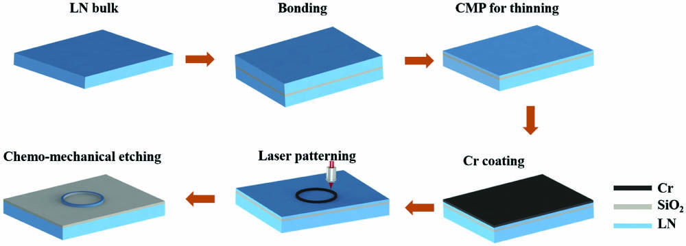
    Fig. 1. Illustration of the fabrication flow of the microrings.
    (a) Optical microscope image of the fabricated microring. (b) Magnified scanning-electron-microscope (SEM) image of the fabricated microring. (c) The SEM image shows that a small slit is cut through the microring with a focused ion beam. (d) The optical microscope image of the ridge waveguide on other LNOI chips for coupling of the microring.
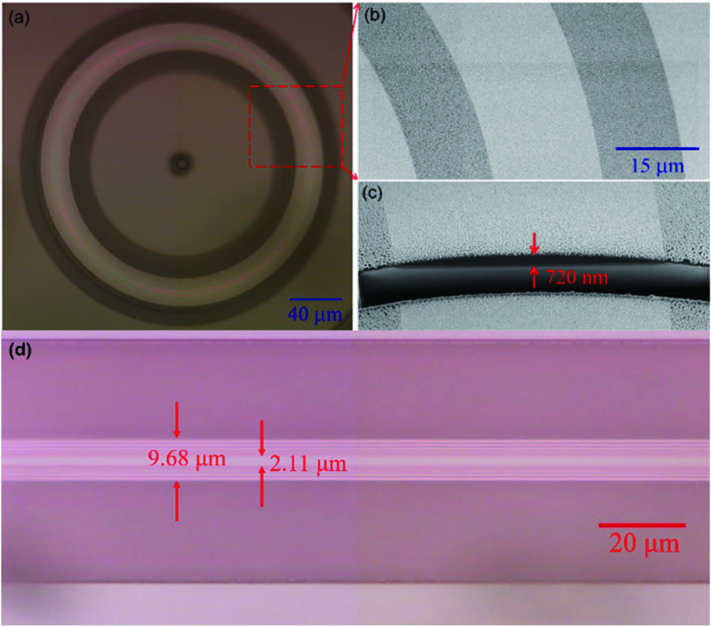
    Fig. 2. (a) Optical microscope image of the fabricated microring. (b) Magnified scanning-electron-microscope (SEM) image of the fabricated microring. (c) The SEM image shows that a small slit is cut through the microring with a focused ion beam. (d) The optical microscope image of the ridge waveguide on other LNOI chips for coupling of the microring.
    (a) Experimental setup for mode characterization. (b) Optical micrograph of the waveguide coupled with the microring. (c) The measured transmission spectrum. (d) and (e) Q factors of the modes fitted by Lorentz-shape curves; insets: the corresponding field distributions of the modes, where the direction presents the radial direction.
    Fig. 3. (a) Experimental setup for mode characterization. (b) Optical micrograph of the waveguide coupled with the microring. (c) The measured transmission spectrum. (d) and (e) Q factors of the modes fitted by Lorentz-shape curves; insets: the corresponding field distributions of the modes, where the direction presents the radial direction.
    Renhong Gao, Ni Yao, Jianglin Guan, Li Deng, Jintian Lin, Min Wang, Lingling Qiao, Wei Fang, Ya Cheng. Lithium niobate microring with ultra-high Q factor above 108[J]. Chinese Optics Letters, 2022, 20(1): 011902
    Download Citation