Author Affiliations
1Nanjing University, College of Engineering and Applied Sciences, Nanjing, China2Nanjing University, Collaborative Innovation Center of Advanced Microstructures, Nanjing, China3Nanjing University, National Laboratory of Solid State Microstructures, Nanjing, China4Nanjing University, Key Laboratory of Intelligent Optical Sensing and Manipulation, Nanjing, China5Research Center for Quantum Sensing, Zhejiang Laboratory, Hangzhou, China6Purple Mountain Laboratories, Nanjing, Chinashow less
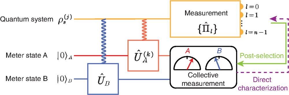
Fig. 1. The schematic diagram for direct characterization of the matrix components of the POVM .
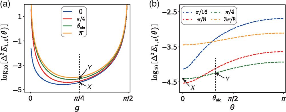
Fig. 2. The measurement precision of the off-diagonal matrix element of the measurement operator in a two-dimensional QS. (a) The variance of is plotted with different for four values of with . (b) The variance of changes with different parameters for the coupling strength . Here, we take and to coincide with our experimental conditions. The points and refer to the precision of directly measuring the off-diagonal matrix entry of the two-dimensional symmetric informationally complete positive operator-valued measure (SIC POVM) with the coupling strength .
Fig. 3. The experimental setup for characterization of the evolution of the quantum measurement. The pulse laser at 830 nm enters a BBO crystal for the upconversion. The generated photons at 415 nm get through a KDP crystal for the spontaneous parametric downconversion, which simultaneously produces a pair of photons. The single photon is heralded by detecting the other one of the pair. The measurement 1 and measurement 2 modules successively implement the unitary transformation and as well as the joint measurement on the MSs. In the following, the unknown quantum detector performs the postselection measurement on the polarization DOF of photons. The quantum detector is composed of the operation of polarization evolution, i.e., “(I) dephasing” and “(II) phase rotation” and the SIC POVM realized by the quantum walk. The abbreviations of the equipment are as follows: PBS, polarizing beam splitter; BBO, -barium borate crystal; KDP, potassium dihydrogen phosphate; HWP, half-wave plate; QWP, quarter-wave plate; PBD, polarizing beam displacer; FWP, full-wave plate; and LCP, liquid-crystal plate.
Fig. 4. (a), (b) The real and the imaginary parts of the matrix components are plotted during the dephasing () and the phase rotation () of the polarization, respectively. The results of the ideal SIC POVM, the CT, and the DT are represented by the pentagrams, hollow markers, and solid markers, respectively. In panels (a) and (b), we connect each pentagram with the point (0, 0), indicating the evolution path of the ideal SIC POVM during the dephasing process as well as changes of the azimuth angles during the phase rotation process. (c) The statistical errors of the matrix components are provided for both the dephasing and the phase rotation process. (d) The precision of after using the completeness condition of the POVM. The theoretical precision, represented by the dashed lines in panels (c) and (d), is inferred from the experimental results of CT. The average photon number per unit time for one collective measurement of the MSs is about .
Fig. 5. The calibration of the equipment in the dephasing and the phase rotation process. (a) The calibration setup. (b) The coefficient changes with the time delay between the wave packets in states and . (c) The relative phase between the states and changes with imposed voltage.