
Sav Chima. X-ray computed tomography of adhesive wicking into carbon foam[J]. High Power Laser Science and Engineering, 2017, 5(4): 04000e28
- High Power Laser Science and Engineering
- Vol. 5, Issue 4, 04000e28 (2017)
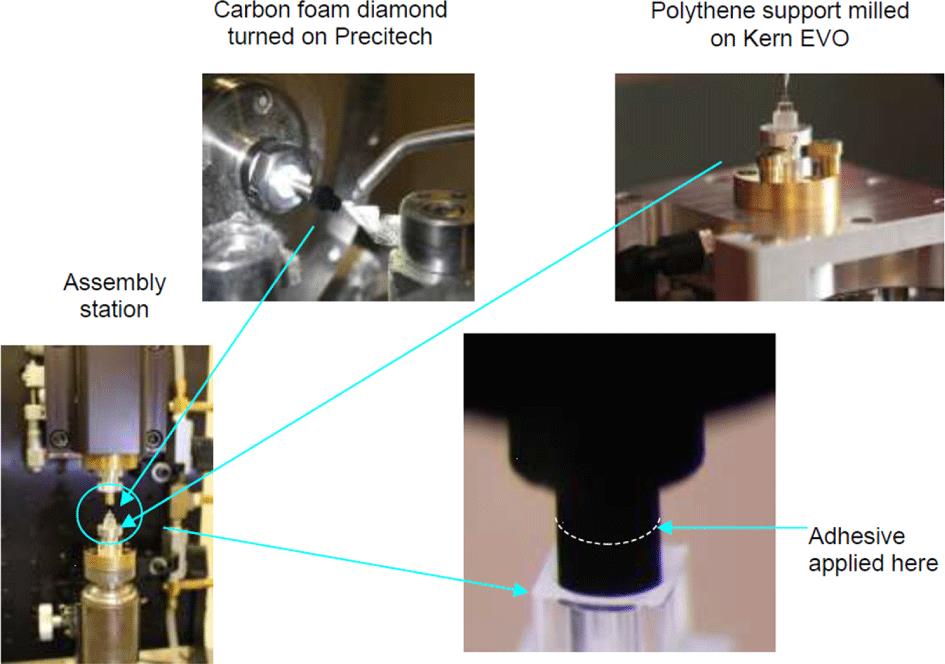
Fig. 1. Component machining, assembly station and adhesive application.
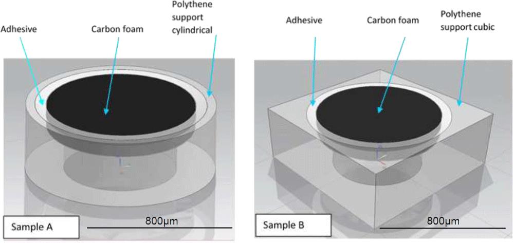
Fig. 2. 3D schematic of Samples A and B, respectively.
Fig. 3. Sample mounted onto X-ray CT holder. The carbon foam is just visible on the top.
Fig. 4. Sample mounted within the X-ray CT system.
Fig. 5. Sample A X-ray CT XY (left image), YZ (right image) views.
Fig. 6. Sample A X-ray CT XY (left image), YZ (right image) views.
Fig. 7. Sample B X-ray CT XY (left image), XZ (right image) views.
Fig. 8. Sample B X-ray CT XY (left image), XZ (right image) views.
Fig. 9. Sample A volume-rendered image showing the distribution of adhesive used to bond the carbon foam to the polythene support.
Fig. 10. Sample B volume-rendered image showing the distribution of adhesive used to bond the carbon foam to the polythene support.
|
Table 1. X-ray acquisition parameters for Sample A.
|
Table 2. X-ray acquisition parameters for Sample B.

Set citation alerts for the article
Please enter your email address
© Copyright 2018-2021 | Chinese Laser Press. All Rights Reserved 沪ICP备15018463号-20