
Xian’e Li, Qilun Zhang, Xianjie Liu, Mats Fahlman. Pinning energies of organic semiconductors in high-efficiency organic solar cells[J]. Journal of Semiconductors, 2023, 44(3): 032201
- Journal of Semiconductors
- Vol. 44, Issue 3, 032201 (2023)
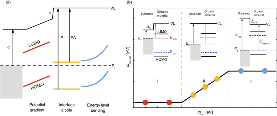
Fig. 1. (Color online) (a) Schematic of the common interface phenomenon at organic/metal or organic/organic interfaces. (b) Schematic illustration of the integer charge transfer (ICT) model.

Fig. 2. (Color online) (a) Schematic illustration of deriving important parameters from UPS characterization. (b) UPS spectra of Y11 spin-coated on different substrates. The spectra of negative pinning region, vacuum level alignment region and positive pinning region are denoted in red, yellow, and blue, respectively.
Fig. 3. (Color online) Dependence of the work function of (a) donor and (b) NFA coated substrates (Φorg/sub) on the work function of bare substrate (Φsub). Data points of PM6, PBDB-T, ITIC, and IT4F are abstracted from Ref. [29].
Fig. 4. (Color online) Schematic illustration of energy levels of donor and acceptor before and after contact. ΔHOMO (Δ′HOMO), ΔLUMO (Δ′LUMO), Γ(Γ′) present the HOMO difference, LUMO difference, and interfacial state energy gap before (after) the donor (D) and acceptor (A) contact. Δ is the interface dipole inducing the vacuum level (VL) shift.
| |||||||||||||||||||||||||||||||||||||||||||||||||||||||||||||||||||||||||||||||||||||||||||||||||||||||||||||||||||||||||||||||||||||||||||||||||||||||||||||||||||
Table 1. Summary of the pinning energies (EICT+,–), ionization potentials (IP), and electron affinities (EA) of donors and acceptors.

Set citation alerts for the article
Please enter your email address
© Copyright 2018-2021 | Chinese Laser Press. All Rights Reserved 沪ICP备15018463号-20