Author Affiliations
1Optoelectronic Technology R&D Department, Beijing Institute of Microelectronics, Chinese Academy of Sciences, Beijing 100029, China2Beijing RSLaser Opto-Electronics Technology Co., Ltd, Beijing 100176, Chinashow less
Fig. 1. Schematic diagram of potential energy for ArF excimer laser
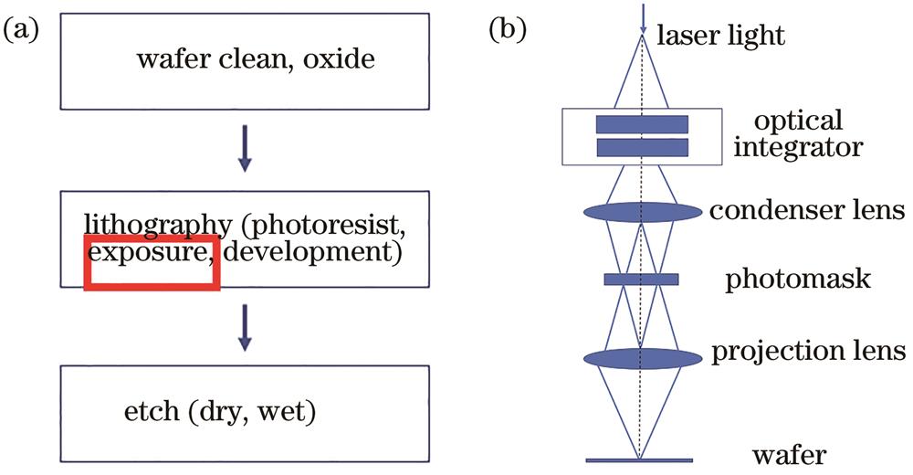
[1] Fig. 2. Position of lithography system in integrated circuit technology and schematic diagram of lithography system. (a) Position; (b) schematic diagram
Fig. 3. Trend of exposure wavelength reduction and theoretical resolution limit for laser source of lithography system
[1] Fig. 4. Diagram of E95 and FWHM
Fig. 5. Schematic of single-chamber excimer laser system
Fig. 6. Cross section of discharge chamber
[10] Fig. 7. Schematic of dual-chamber excimer laser system
Fig. 8. Light path of MOPA dual-chamber
Fig. 9. Ring light path of MOPRA dual-chamber
Fig. 10. Light path of injection lock structure
Fig. 11. Schematic of clearance in discharge region
[1] Fig. 12. Basic schematic of gas lifetime controller system
[40] Fig. 13. Diagram of light propagation
Fig. 14. Intensity distributions of Gaussian mode and excimer mode and their curves of knife edge. (a) Beam of Gaussian fundamental mode
[48]; (b) beam of excimer laser
[48]; (c) relationship between knife edge ratio
∈ and
Dc/
σx for several Gaussian modes
[49] Fig. 15. Recent excimer laser source is improved in many aspects, including production ratio, durability and optical performance
Fig. 16. Concept schematic of Gigaphoton hTGM Neon recycling system
[54] Fig. 17. Concept schematic of Cymer XLGR Neon recycling system
[56] Fig. 18. Relationship between change of E95 and change of critical dimension is basically linear correlation
Fig. 19. Excimer laser inspection system ExciStar S-Industrial designed by Coherent Inc
[64] Fig. 20. Cross section of fiber structure used in laser inspection system
[65] | Halogen | Excimer laser gasmixture |
|---|
| Excimer | | ArF | KrCl | KrF | XeBr | XeCL | XeF(B-X) | | Wavelength /nm | 157 | 193 | 222 | 248 | 262 | 308 | 351 |
|
Table 1. Wavelengths of different excimer lasers
| Year | Research institution | Landmark of progression |
|---|
| 1970 | Lebedev Physical Institute in Moscow | The first excimer lasing was invented | | 1974 | University of Cambridge,Cambridge,UK;Kansas State University,Kansas,USA;Avco Everett Research Laboratory,Everett,Massachusetts,USA | The fluorescence spectra of rare-gas halides were investigated | | 1975 | Naval Research Laboratory,Washington,USA;Northrop Research and Technology Center,Hawthorne,USA;Avco Everett Research Laboratory,Everett,Massachusetts,USA;Sandia Laboratories,Albuquerque,USA | The first laser of exciplexes was demonstrated | | 1979 | Lambda Physik | The first commercial excimer laser system was developed | | 1980 | IBM | Jain proposed the concept of excimer laser on lithography | | 1980 | IBM | The lithographic exposure experiment by excimer lasers in contact mode was carried out | | 1982 | IBM | With the modified Micralign system,the projection lithography by excimer laser was experimentally demonstrated |
|
Table 2. Development history of excimer lasers
| Company | Model | Exposure type | Resolution /nm | Laser source | NA | Output rate(Wafer /h) |
|---|
| ASML | NXT1980Di | Double immersion step-and-scan exposure | 38 | 193 nm ArF | 1.35 | 275 | | NXT1950i | 175 | | XT1450H | Double dry step-and-scan exposure | 65 | 0.93 | 162 | | XT1000K | 80 | 248 nm KrF | 180 | | XT860K | 110 | 0.80 | 210 | | XT400K | 350 | 365 nm high pressure mercury lamp | 0.65 | 220 | | PAS5500/1150C | Single step-and-scan exposure | 90 | 193 nm ArF | 0.75 | 135 | | PAS5500/850D | NA | 110 | 248 nm KrF | 0.80 | 145 | | PAS5500/450F | NA | 220 | 365 nm high pressure mercury lamp | 0.65 | 150 | | Nikon | NSR-S631E | immersion step-and-scan exposure | 38 | 193 nm ArF | 1.35 | 270 | | NSR-S621D | 200 | | NSR-S322F | step-and-scan exposure | 65 | 248 nm KrF | 0.92 | 230 | | NSR-S210D | 110 | 0.86 | 176 | | Canon | FPA-6300ES6a | step-and-scan exposure | 90 | 248 nm KrF | 0.86 | 200 |
|
Table 3. Some models of lithography systems for ASML, Nikon and Canon, and laser sources of these systems
| Critical dimension |
|---|
| Lithography | Lens aberrations | Focus | Dose control | Optical proximity effect | Illumination | | Lasers | Linewidth | Wavelength stability | Energy stability | Bandwidth stability | Beam stability | | Spectral shape | | Beam stability | Beam stability | Degree of polarization |
|
Table 4. Influence of laser source parameters on critical dimension of lithography system
| Process node /nm | Type | Linewidth(FWHM)/pm | Center wavelength stability /pm |
|---|
| 180‒110 | KrF single-chamber | ≤0.35‒0.60 | ≤0.050 | | 90‒65 | ArF dual-chamber,dry | ≤0.25 | ≤0.030 | | 45‒28 | ArF dual-chamber,immersion | ≤0.25 | ≤0.030 | | 14 | ArF dual-chamber,immersion,multiple exposure | ≤0.25 | ≤0.018 | | 7 | ArF dual-chamber,immersion,multiple exposure | ≤0.25 | ≤0.012 |
|
Table 5. Relationship of process node with linewidth and center wavelength stability
| Year | Cymer | Gigaphoton |
|---|
| 2015 | With GLX system and Neon reduction system,75% of Neon usage is saved for XLR700ix | Helium is replaced by Nitrogen for GT64A,and it saves 80 kL Nitrogen per year;For GT63A,with help of eTGM Neon reduction system,usage of Neon is reduced from 200 kL per year to 100 kL per year | | 2016 | | 2017 | | 2018 | On basis of Neon reduction system,90% Neon is saved by XLGR Neon recycling system for XLR800ix | On basis of eTGM,92% Neon is recycled by hTGM Neon recycling system for GT65A | | 2019 |
|
Table 6. Comparison of gas reduction and recycling between Cymer and Gigaphoton in recent years
| Year | Cymer | Gigaphoton |
|---|
| 2015 | Maximum lifetime of XLR700ix is 90 billion pulses | Maximum chamber lifetime of GT64A is 40 billion pulses | | 2016 | | 2017 | | 2018 | Maximum chamber lifetime of XLR800ix is 120 billion pulses | Maximum chamber lifetime of GT64A is 60 billion pulses | | 2019 | | 2020 | Expected maximum chamber lifetime of XLR900ix is 180 billion pulses | Maximum chamber lifetime of GT66A-1 is 100 billion pulses | | Future | NA | Maximum chamber lifetime of GT66A-1 is 120 billion pulses and maximum line narrowing module lifetime is 180 billion pulses |
|
Table 7. Comparison of laser lifetime between Cymer and Gigaphoton in recent years

![Schematic diagram of potential energy for ArF excimer laser[1]](/richHtml/lop/2022/59/9/0922020/img_01.jpg)