
Zhe Yang, Kexin Huang, Machi Zhang, Dong Ruan, Junlin Li, "Derivative ghost imaging," Chin. Opt. Lett. 20, 011101 (2022)
- Chinese Optics Letters
- Vol. 20, Issue 1, 011101 (2022)
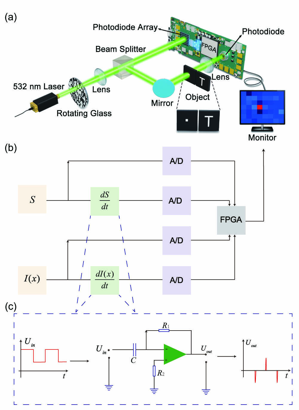
Fig. 1. Experimental schematic. (a) The pseudo-thermal light is generated by a 532 nm laser illuminating a rotating light-modulating glass disk. The HBT experiment used a small hole in the object plane, and the GI experiment used the letter T as the object. (b) The bucket detector signal S and the reference light signal I(x) are received by the photodetectors to produce a photocurrent. The photocurrent is sampled by the analog-to-digital converter (A/D) to obtain S and I(x), and is transmitted to the field programmable gate array (FPGA). Simultaneously, the photocurrents enter the differentiators to produce the derivative signals, which then undergo A/D sampling and are transmitted to the FPGA for calculation of the experimental results. In the HBT experiment, the signal flow is similar to (b), with I(x1) and I(x2) replacing S and I(x). (c) The differentiators for S and I(x) are implemented by differentiating the operational amplitude circuits.
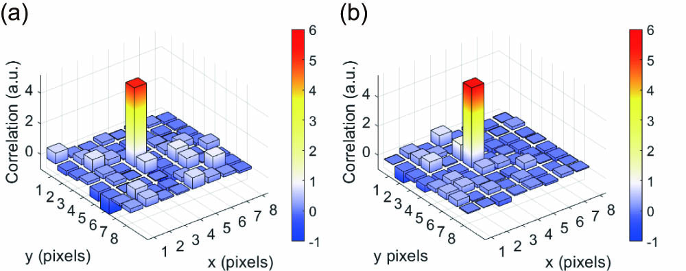
Fig. 2. Experimental results of (a) the first-order derivative HBT and (b) standard HBT. The number of measurements M in both cases was 512.
Fig. 3. (a) Object of the GI experiment, and the experimental results of (b) the first-order derivative GI and (c) standard GI. The number of measurements M in each case was 1024.
Fig. 4. Experimental results of (a) the first-order derivative HBT, (b) standard HBT (the number of measurements M in each case was 256), and (c) combination of (a) and (b) by simple addition after rescaling. The experimental results of (d) first-order derivative GI, (e) standard GI (the number of measurements M in each case was 512), and (f) the combination of (d) and (e).
Fig. 5. Experimental results of the standard GI, the first-order derivative GI, and the combination of the two within different sample numbers M.
Fig. 6. Experimental results of 〈I (x0)I′(x)〉 − 〈I (x0)〉〈I′ (x)〉. x0 is chosen as (a) row 3 and column 3 and (b) row 5 and column 5, respectively.


Set citation alerts for the article
Please enter your email address

© Copyright 2018-2021 | Chinese Laser Press. All Rights Reserved 沪ICP备15018463号-20