• Photonics Research
  • Vol. 10, Issue 4, 843 (2022)
Yuxiang Jia1、2, Jiafu Wang1、2、3、*, Yajuan Han1、2、4、*, Ruichao Zhu1、2, Zhongtao Zhang1、2, Jie Yang1、2, Yueyu Meng1、2, Yongfeng Li1、2, and Shaobo Qu1、2
Author Affiliations
  • 1Department of Basic Sciences, Air Force Engineering University, Xi’an 710051, China
  • 2Shaanxi Key Laboratory of Artificially-Structured Functional Materials and Devices, Xi’an 710051, China
  • 3e-mail: wangjiafu1981@126.com
  • 4e-mail: mshyj_mail@126.com
  • show less
    DOI: 10.1364/PRJ.447037 Cite this Article Set citation alerts
    Yuxiang Jia, Jiafu Wang, Yajuan Han, Ruichao Zhu, Zhongtao Zhang, Jie Yang, Yueyu Meng, Yongfeng Li, Shaobo Qu. Quasi-omnibearing retro-reflective metagrating protected by reciprocity[J]. Photonics Research, 2022, 10(4): 843 Copy Citation Text show less
    Schematic illustration of the quasi-omnibearing RRMG: the green area represents specular reflection when the incident angle is smaller than the critical angle; retro-reflections are achieved in the red-highlighted areas in all four quarters due to −2nd-order EOD; the left inset illustrates the re-radiation process of EM waves with reversed wave vector. The angles are defined according to the spherical coordinate system, where the incident angle is defined the same as the polar angle.
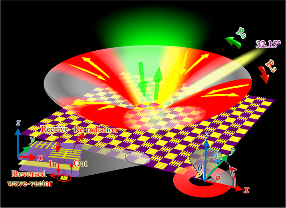
    Fig. 1. Schematic illustration of the quasi-omnibearing RRMG: the green area represents specular reflection when the incident angle is smaller than the critical angle; retro-reflections are achieved in the red-highlighted areas in all four quarters due to 2nd-order EOD; the left inset illustrates the re-radiation process of EM waves with reversed wave vector. The angles are defined according to the spherical coordinate system, where the incident angle is defined the same as the polar angle.
    Reflection Wood anomaly (RWA) lines and the metagrating element based on reciprocity of SPA. (a) Diffraction order chart composed of a series of RWA lines. (b) Schematic illustration and simulated results of the SPA fed by a coaxial port: (i) perspective and side view of the SPA with all dimensions marked, where p=26.11 mm, lx=12.5 mm, ly=12.0 mm, w=0.2 mm, th1=1.5 mm; (ii) simulated S11 and total efficiency of the SPA; (iii) surface current on the SPA at 15.0 GHz; (iv) far-field radiation pattern at 15.0 GHz; (v) realized gain at 15.0 GHz. (c) Far-field radiation pattern of the SPA: (i) far-field radiation pattern at 15.0 GHz when the SPA is fed by a coaxial port; (ii) off-set far-field re-radiation pattern under oblique incidence when the coaxial port is short-circuited; (iii) available diffraction orders of the metagrating, denoted by red (m=−2), yellow (m=−1), and green (m=0) arrows.
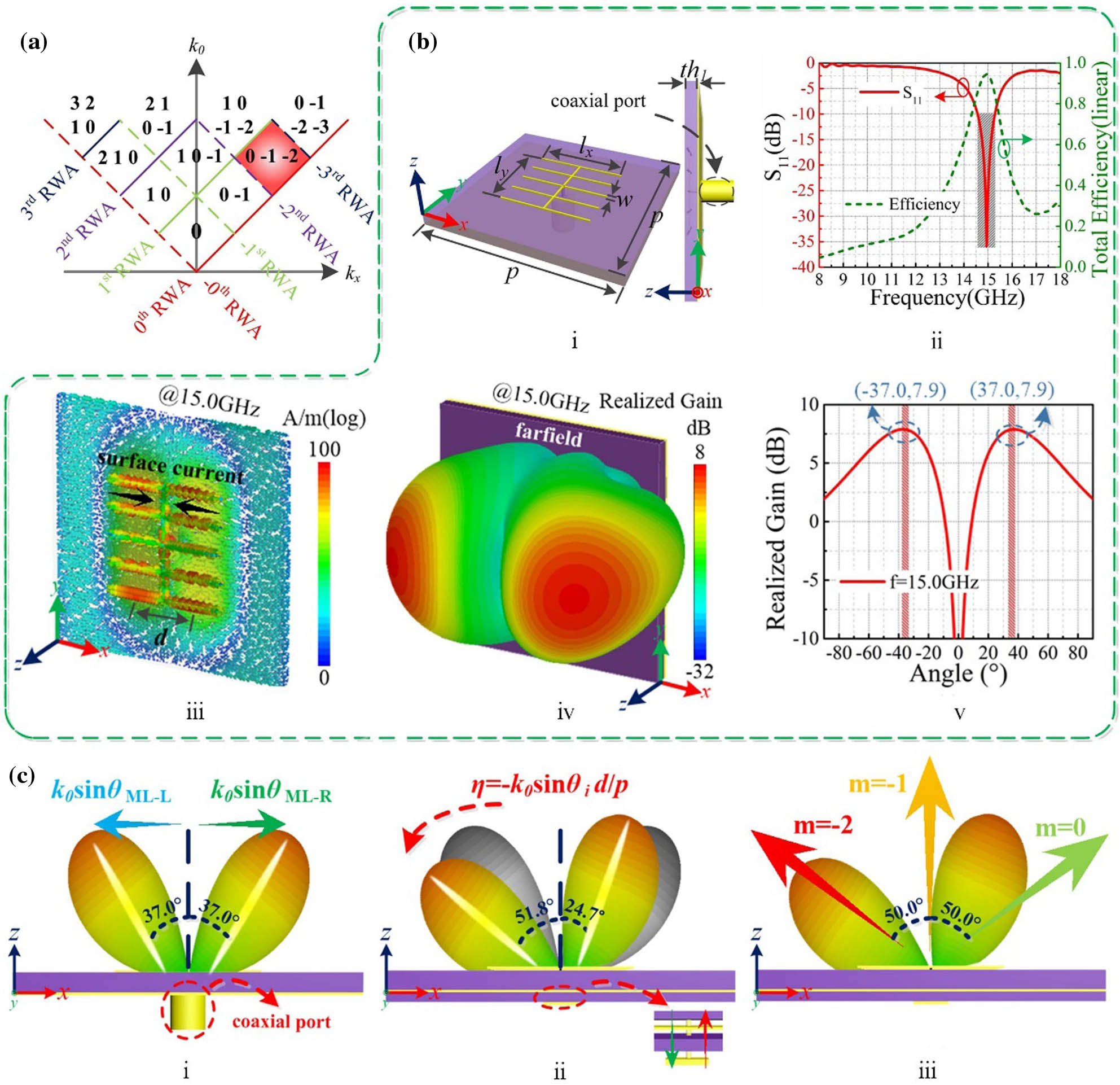
    Fig. 2. Reflection Wood anomaly (RWA) lines and the metagrating element based on reciprocity of SPA. (a) Diffraction order chart composed of a series of RWA lines. (b) Schematic illustration and simulated results of the SPA fed by a coaxial port: (i) perspective and side view of the SPA with all dimensions marked, where p=26.11  mm, lx=12.5  mm, ly=12.0  mm, w=0.2  mm, th1=1.5  mm; (ii) simulated S11 and total efficiency of the SPA; (iii) surface current on the SPA at 15.0 GHz; (iv) far-field radiation pattern at 15.0 GHz; (v) realized gain at 15.0 GHz. (c) Far-field radiation pattern of the SPA: (i) far-field radiation pattern at 15.0 GHz when the SPA is fed by a coaxial port; (ii) off-set far-field re-radiation pattern under oblique incidence when the coaxial port is short-circuited; (iii) available diffraction orders of the metagrating, denoted by red (m=2), yellow (m=1), and green (m=0) arrows.
    Schematic illustrations of 1D and 2D metagratings and simulated results. (a) Perspective view of (i) 1D RRMG, (ii) 1D-SPA, (iii) 2D RRMG, and (iv) 2D-SPA. (b) 3D waterfall diagram of diffraction angles under different incident angles with various frequencies. Simulated results of the (c) 1D and (d) 2D RRMG: bistatic RCS curves (top panels) and corresponding far fields (bottom panels) under incident angles (i) 0°, (ii) 25.0°, (iii) 50.0°, and (iv) 65.0° with azimuth angle φ=0°.
    Fig. 3. Schematic illustrations of 1D and 2D metagratings and simulated results. (a) Perspective view of (i) 1D RRMG, (ii) 1D-SPA, (iii) 2D RRMG, and (iv) 2D-SPA. (b) 3D waterfall diagram of diffraction angles under different incident angles with various frequencies. Simulated results of the (c) 1D and (d) 2D RRMG: bistatic RCS curves (top panels) and corresponding far fields (bottom panels) under incident angles (i) 0°, (ii) 25.0°, (iii) 50.0°, and (iv) 65.0° with azimuth angle φ=0°.
    Simulated results of 2D RRMG and photos of 1D and 2D RRMG prototypes. (a) Bistatic RCS curves (top panels) and corresponding far fields (bottom panels) for azimuth angles of (i) 90.0°, (ii) 180.0°, and (iii) 270.0° under incident angle 50.0°. (b) Simulated broadband retro-reflection results of (i) 1D RRMG, (ii) 2D RRMG, and (iii) SAMP under incident angle 50.0° with azimuth angle φ=0°. (c) Front and back sides of the protype photos of (i), (ii) 1D RRMG, and (iii), (iv) 2D RRMG, respectively, together with zoomed view of the details.
    Fig. 4. Simulated results of 2D RRMG and photos of 1D and 2D RRMG prototypes. (a) Bistatic RCS curves (top panels) and corresponding far fields (bottom panels) for azimuth angles of (i) 90.0°, (ii) 180.0°, and (iii) 270.0° under incident angle 50.0°. (b) Simulated broadband retro-reflection results of (i) 1D RRMG, (ii) 2D RRMG, and (iii) SAMP under incident angle 50.0° with azimuth angle φ=0°. (c) Front and back sides of the protype photos of (i), (ii) 1D RRMG, and (iii), (iv) 2D RRMG, respectively, together with zoomed view of the details.
    Measured results of 1D and 2D RRMGs. (a) 1D and (b) 2D RRMGs bistatic reflection coefficients under incident angles (i) 0°, (ii) 25.0°, (iii) 50.0°, and (iv) 65.0° with azimuth angle φ=0°. (c) 2D RRMG bistatic reflection coefficients for azimuth angles (i) 90.0°, (ii) 180°, and (iii) 270° under incident angle 50.0°, and (iv) measurement environment in microwave anechoic chamber. (d) Measured broadband retro-reflection results of (i) 1D RRMG, (ii) 2D RRMG, and (iii) SAMP under incident angle 50.0° with azimuth angle φ=0°.
    Fig. 5. Measured results of 1D and 2D RRMGs. (a) 1D and (b) 2D RRMGs bistatic reflection coefficients under incident angles (i) 0°, (ii) 25.0°, (iii) 50.0°, and (iv) 65.0° with azimuth angle φ=0°. (c) 2D RRMG bistatic reflection coefficients for azimuth angles (i) 90.0°, (ii) 180°, and (iii) 270° under incident angle 50.0°, and (iv) measurement environment in microwave anechoic chamber. (d) Measured broadband retro-reflection results of (i) 1D RRMG, (ii) 2D RRMG, and (iii) SAMP under incident angle 50.0° with azimuth angle φ=0°.
    Simulated results of (a) 1D and (b) 2D metagratings under TE polarized waves at 15.0 GHz: bistatic RCS curves (top panels) and corresponding far fields (bottom panels) under incident angles (i) 0°, (ii) 25.0°, (iii) 50.0°, and (iv) 65.0° with azimuth angle φ=0°.
    Fig. 6. Simulated results of (a) 1D and (b) 2D metagratings under TE polarized waves at 15.0 GHz: bistatic RCS curves (top panels) and corresponding far fields (bottom panels) under incident angles (i) 0°, (ii) 25.0°, (iii) 50.0°, and (iv) 65.0° with azimuth angle φ=0°.
    Yuxiang Jia, Jiafu Wang, Yajuan Han, Ruichao Zhu, Zhongtao Zhang, Jie Yang, Yueyu Meng, Yongfeng Li, Shaobo Qu. Quasi-omnibearing retro-reflective metagrating protected by reciprocity[J]. Photonics Research, 2022, 10(4): 843
    Download Citation