• Photonics Research
  • Vol. 10, Issue 4, 843 (2022)
Yuxiang Jia1、2, Jiafu Wang1、2、3、*, Yajuan Han1、2、4、*, Ruichao Zhu1、2, Zhongtao Zhang1、2, Jie Yang1、2, Yueyu Meng1、2, Yongfeng Li1、2, and Shaobo Qu1、2
Author Affiliations
  • 1Department of Basic Sciences, Air Force Engineering University, Xi’an 710051, China
  • 2Shaanxi Key Laboratory of Artificially-Structured Functional Materials and Devices, Xi’an 710051, China
  • 3e-mail: wangjiafu1981@126.com
  • 4e-mail: mshyj_mail@126.com
  • show less
    DOI: 10.1364/PRJ.447037 Cite this Article Set citation alerts
    Yuxiang Jia, Jiafu Wang, Yajuan Han, Ruichao Zhu, Zhongtao Zhang, Jie Yang, Yueyu Meng, Yongfeng Li, Shaobo Qu. Quasi-omnibearing retro-reflective metagrating protected by reciprocity[J]. Photonics Research, 2022, 10(4): 843 Copy Citation Text show less

    Abstract

    Reciprocity is ubiquitous in antennas for receiving and radiating electromagnetic (EM) waves, i.e., if an antenna has good receiving performance at a given direction, it also has good radiation performance in that direction. Inspired by this, we propose a method of designing a quasi-ominibearing retro-reflective metagrating (RRMG) protected by the reciprocity of antennas. Based on the second-order mode around 15.0 GHz of a short-circuited structured patch antenna (SPA), incident transverse magnetic waves can be received, channeled into the coaxial lines, reflected by the shortened end, and finally re-radiated into free space with a reversed wave vector. RRMGs are contrived consisting of this identical SPA, with a grating constant allowing ±2nd-, ±1st-, and zeroth-order diffractions. Oblique incidence, plus the tilted nulls of the re-radiation pattern, can eliminate -1st, zeroth, +1st, and +2nd orders, and only the -2nd order is left to achieve retro-reflections. Prototypes were fabricated and measured. Simulated and measured results show that the RRMGs maintain only -2nd-order diffraction for incident angles 32.2°θi<90.0° in four quadrants, and that RRMGs can achieve quasi-omnibearing retro-reflections for θi=50.0°. The use of higher-order diffraction brings more degrees of freedom in manipulating EM waves, and this strategy can be readily extended to millimeter waves, THz wave, or even optical regimes.

    1. INTRODUCTION

    Retro-reflection, which channels reflected electromagnetic (EM) waves towards the source [1,2], can significantly enhance the backscattering of a given target and thus can enhance its radar cross section (RCS) to increase detectability of an object by radars [3]. Retro-reflections have important applications in many fields [47], such as false targets, sea rescues, and target tracking. These practical applications exert more and more demanding requirements on retro-reflectors, which are expected to be flat, lightweight, or even foldable. However, conventional dihedral [8,9] or trihedral [10] corner reflectors are prohibitive because of their large volume, heavy weight, and other factors. Therefore, it is necessary to develop planar or even conformal retro-reflectors based on new physical mechanisms. Metasurfaces are the two-dimensional (2D) counterparts of metamaterials [1115], which can flexibly control EM wavefronts [1619] to implement the functions of deflected reflection [2022], focusing [2325], surface wave excitation [26,27], holography [2831], etc. Metasurfaces usually consist of discrete elements to form gradient phase profiles, which have been widely investigated as a tool of controlling reflection [32,33] and transmission [34,35] of EM waves. To solve parasitic reflections in undesired directions, recent works explore new physical mechanisms; for example, strongly nonlocal response is required for perfect performances [36,37]. Metagratings and Huygens’ metasurface are adopted by Alù [38] and Eleftheriades [39], respectively, to achieve perfect anomalous reflections. Furthermore, Faraon et al. [33] adopt cascade metasurfaces, composed of two vertically stacked planar metasurfaces that perform a spatial Fourier transform and a spatially varying momentum, achieving retro-reflections under a continuous and wide incident angle domain as much as possible.

    However, these aforementioned works are all on wavefront controls in one azimuth angle, limiting their practical applications to a certain extent. If retro-reflections could be realized within the full azimuth zone, practical applications of flat retro-reflectors could be heavily promoted. Omnibearing retro-reflections first require that the array element and scattering pattern both have continuous rotational symmetry [40]. Wavefront controls utilizing phase gradients among structural units cannot be adopted, due to the single direction phase profile. Instead, identical structural elements must be stipulated to make up the flat array. Very recently, it has been demonstrated that metasurfaces with identical elements, rather than gradient ones, are capable of obtaining near-unity diffraction efficiencies. This is done by harnessing decaying pathways of resonance cavity modes into higher diffraction orders, which is referred to as extraordinary optical diffraction (EOD) [41]. This method does not need a library of different meta-atoms with various geometries or sizes to produce customized phase profiles. By modulating the displacements between identical meta-atoms rather than the geometrical parameters, metagratings can produce robust detour phase profiles that are irrespective of wavelength or incident angle, opening the possibility of arbitrary wavefront shaping with extreme angle tolerance in a broadband spectral range [42].

    In this paper, we propose a facile method of designing a quasi-omnibearing retro-reflective metagrating (RRMG) by simultaneously regulating the grating constant and radiation pattern based on the reciprocity of antennas. The RRMG is composed of 2D arrays of identical structured patch antennas (SPAs), with a fixed grating constant to match the diffraction orders, allowing 2nd, 1st, zeroth, +1st, and +2nd diffraction orders. To maintain only higher-order diffraction, the radiation pattern of the SPA is off-set, which is realized by sealing the coaxial via on the bottom of the SPA using a square patch (called a reverser hereafter). When transverse magnetic (TM) waves impinge onto the RRMG with an oblique incident angle, they are funneled into the coaxial via, reflected backwards by the reverser, and then re-radiated by the SPA. The two main lobes (i.e., 51.78° and 24.67°) of the re-radiation pattern are made to avoid the 1st- and zeroth-order diffraction channels. Oblique incidence, together with the tilted nulls of the re-radiation pattern, can eliminate 1st, zeroth, +1st, and +2nd orders, and only 2nd-order is left to enable retro-reflections. Due to the rotational symmetry of the element (as shown in the inset in Fig. 1), quasi-omnibearing retro-reflections can be realized under a prescribed oblique incident angle, i.e., θi=50.0°. Figure 1 illustrates the operating principle of 2D RRMG, where the green area represents specular reflection for an incident angle less than the critical angle. Retro-reflections are achieved in the red-highlighted areas under the incident angle θi=50.0° due to 2nd-order EOD. 1D and 2D RRMG prototypes were designed and fabricated. Both simulated and measured results show that RRMGs can realize retro-reflections in all four quadrants of the azimuth zone under the prescribed incident angle, which convincingly verifies the design method. The grating constant is directly proportional to the absolute value of the maximal diffraction order. The higher the diffraction order, the more degrees of freedom (DOFs) of RRMGs in manipulating EM waves. Rather than utilizing zeroth- or 1st-order EOD [4043], this work utilizes 2nd-order EOD, which increases the DOFs for designing RRMGs and also provides more flexibility in controlling EM waves. The demonstrated capability of controlling diffraction channels of RRMGs provides a facile way of realizing multi-functional devices, and this strategy can be readily extended to higher frequencies such as THz or even optical regimes.

    Schematic illustration of the quasi-omnibearing RRMG: the green area represents specular reflection when the incident angle is smaller than the critical angle; retro-reflections are achieved in the red-highlighted areas in all four quarters due to −2nd-order EOD; the left inset illustrates the re-radiation process of EM waves with reversed wave vector. The angles are defined according to the spherical coordinate system, where the incident angle is defined the same as the polar angle.

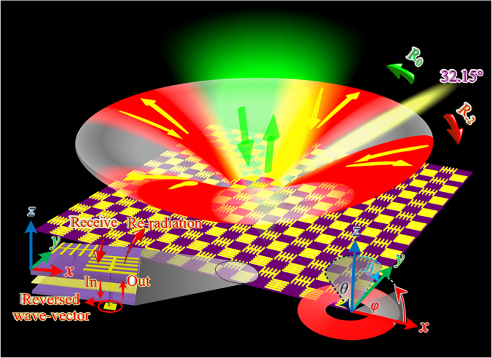
    Figure 1.Schematic illustration of the quasi-omnibearing RRMG: the green area represents specular reflection when the incident angle is smaller than the critical angle; retro-reflections are achieved in the red-highlighted areas in all four quarters due to 2nd-order EOD; the left inset illustrates the re-radiation process of EM waves with reversed wave vector. The angles are defined according to the spherical coordinate system, where the incident angle is defined the same as the polar angle.

    2. RESULTS

    A. Possible Orders of Diffraction by Adjusting the Grating Constant and Radiation Pattern Artificial Design

    To realize higher-order EOD based on the reciprocity of patch antennas for EM wave reception and radiation, two main factors need to be considered simultaneously. On one hand, the grating constant needs to match the wave vector of desired diffraction orders. On the other hand, the re-radiated main lobe of the patch antenna should be aligned along the direction of desired diffraction order as much as possible, so as to steer most EM energy to the desired order of diffraction. In this part, we will elaborate the theory and design method of realizing higher-order EOD by considering these two aspects, that is, the grating constant of the metagratings and the radiation pattern of the patch antenna.

    From the perspective of momentum conservation, when a beam of EM waves carrying free-space wave vector k0 with incident angle θi illuminates the metagrating, the relation between incident wave vector kx=k0·sinθi and grating wave vector ζ is governed by kx+m·ζ=±k0,where m=0,±1,±2 is an integer and represents the diffraction order. Wave vector ζ=2π/p is the grating wave vector imparted by the metagrating, where p is the grating constant (element period of metagrating). From the point of view of tangential wave vector conservation, the incident tangential wave vector k0·sinθi, diffraction wave vector k0·sinθr, and grating wave vector ζ satisfy k0·sinθi+m·ζ=k0·sinθr.

    The diffraction order chart can be obtained as shown in Fig. 2(a) according to Eq. (1), also called reflection Wood anomaly (RWA) lines [43]. It can be seen from the RWA that there are various order diffractions with the increase in grating wave vector ζ, and only evanescent waves exist without radiation below the zeroth-order diffraction ray, which is also known as the light line as denoted by the red lines in Fig. 2(a). Obviously, with increasing tangential wave vector kx, the corresponding diffraction order m will also be increased. That is to say, the DOFs of metagratings will also be increased, which is the focus of this work.

    Reflection Wood anomaly (RWA) lines and the metagrating element based on reciprocity of SPA. (a) Diffraction order chart composed of a series of RWA lines. (b) Schematic illustration and simulated results of the SPA fed by a coaxial port: (i) perspective and side view of the SPA with all dimensions marked, where p=26.11 mm, lx=12.5 mm, ly=12.0 mm, w=0.2 mm, th1=1.5 mm; (ii) simulated S11 and total efficiency of the SPA; (iii) surface current on the SPA at 15.0 GHz; (iv) far-field radiation pattern at 15.0 GHz; (v) realized gain at 15.0 GHz. (c) Far-field radiation pattern of the SPA: (i) far-field radiation pattern at 15.0 GHz when the SPA is fed by a coaxial port; (ii) off-set far-field re-radiation pattern under oblique incidence when the coaxial port is short-circuited; (iii) available diffraction orders of the metagrating, denoted by red (m=−2), yellow (m=−1), and green (m=0) arrows.

    Figure 2.Reflection Wood anomaly (RWA) lines and the metagrating element based on reciprocity of SPA. (a) Diffraction order chart composed of a series of RWA lines. (b) Schematic illustration and simulated results of the SPA fed by a coaxial port: (i) perspective and side view of the SPA with all dimensions marked, where p=26.11  mm, lx=12.5  mm, ly=12.0  mm, w=0.2  mm, th1=1.5  mm; (ii) simulated S11 and total efficiency of the SPA; (iii) surface current on the SPA at 15.0 GHz; (iv) far-field radiation pattern at 15.0 GHz; (v) realized gain at 15.0 GHz. (c) Far-field radiation pattern of the SPA: (i) far-field radiation pattern at 15.0 GHz when the SPA is fed by a coaxial port; (ii) off-set far-field re-radiation pattern under oblique incidence when the coaxial port is short-circuited; (iii) available diffraction orders of the metagrating, denoted by red (m=2), yellow (m=1), and green (m=0) arrows.

    Assume that the retro-reflection is achieved at a specific incident angle θi and selected frequency f0 (the corresponding wavelength is λ0). That is, the signs of reflection angle θr and incident angle θi are opposite, with the same value. The grating constant for the mth (where m0) diffraction order can be obtained as pm=mλ0/2sinθi.

    It can be seen from Eq. (3) that diffraction order m must be negative since the grating constant is always positive. Previous works [4043] achieved retro-reflections based on 1st-order EOD utilizing identical elements, i.e., k0·sinθiζ=k0·sinθi, and then p1=λ0/2sinθi. Obviously, if 2nd-order EOD can be achieved, the corresponding grating constant is p2=2λ0/2sinθi, which is twice as large as p1. It means that the metagrating has higher DOFs with increasing diffraction order m. This work takes this property of higher-order diffraction to extend 1D retro-reflections to 2D. For the sake of simplicity but without loss of generality, we increase the diffraction order to 2nd order as an example, and select the central frequency f0=15.0  GHz of Ku-band as the design frequency (the wavelength is λ0=20.0  mm). The retro-reflection is assumed to occur under the incident angle of θi0=50.0°. Therefore, the grating constant can be obtained as p0=2λ0/2sinθi026.11  mm according to Eq. (4) when the diffraction order is 2nd. From Eq. (4), it can be calculated that the critical incident angle is θc=arcsin(2λ0/p01)32.2°, that is, k0·sinθi2·ζ=k0·sinθr.

    To achieve higher-order EOD as denoted by the red subareas surrounded by zeroth, ±1st, ±2nd, and ±3rd RWAs in Fig. 2(a), the incident tangential wave vector kx and free-space wave vector k0 should satisfy the following conditions: k02πp<kx<k0&4πpk0<kx<6πpk0,kx>0,k0<kx<2πpk0&k06πp<kx<k04πp,kx<0.

    Combining Eq. (4) and inequality (5), we can obtain relationship (6): 1sinθi<sinθi<1&2sinθi1<sinθi<3sinθi1.

    In this way, we can obtain that under incident angle ranges from 32.2° to 90.0°, the possible diffraction orders include zeroth, 1st, and 2nd orders as denoted by the red areas in Fig. 2(a). To achieve high-efficiency 2nd-order diffraction, it is necessary to eliminate zeroth and 1st orders of diffraction. To this end, we resort to the receiving–transmitting reciprocity of antennas and utilize higher-order modes of antennas to design their radiation patterns.

    The SPA is the basic element of the metagrating, which is a kind of typical sandwich structure with grating constant p0 as denoted in Fig. 2(b). The SPA structure is patterned on a Rogers dielectric spacer [εr=2.55(1+0.0026j), thickness th1=1.5  mm] backed by a metallic ground. The metallic structure of the SPA is composed of five identical lines with length lx=12.5  mm and width w=0.2  mm, which are evenly spaced and connected by a microstrip line with length ly=12.0  mm and width w. It can be seen from the side view of the SPA that the element is fed by a coaxial port, and the feeding position is in the center. The specific size of the circular hollow on the metal plate of the intermediate layer is Dv=1.3  mm, playing the role of adjusting the impedance matching between the feed and the patch antenna.

    To evaluate the antenna performance of the SPA element, simulated results are obtained utilizing CST Microwave Studio with “Open add Space” boundaries in x, y, and z directions to simulate the radiation characteristics, surface current distribution, far-field radiation, and realized gain of the element, as denoted in Figs. 2(bii), 2(biii), 2(biv), and 2(bv), respectively. It can be found from Fig. 2(bii) that the bandwidth with |S11|<10.0  dB spans from 14.5 GHz to 15.2 GHz, and the total efficiency is higher than 82.0% within this bandwidth. The transmission direction of the surface current on the SPA shown in Fig. 2(biii) is symmetrical with respect to the H-plane, which means that the radiation mode of the SPA element is the second-order mode at 15.0 GHz; and the radiation has a good linear polarization state, i.e., TM mode. The far-field pattern in Fig. 2(biv) exhibits double beams in the xoz plane, which is symmetrical with respect to the H-plane, further verifying that the radiation mode of the SPA is the second-order mode. The realized gain of the SPA element is about 7.9 dB, and the directivity reaches 8.1 dBi as shown in Fig. 2(bv); the two main lobe directions are 37.0° and 37.0°. Thus, a conclusion can be drawn from the performance of the SPA element that it can radiate efficiently around 15.0 GHz, and the radiation pattern has double beams symmetrical about the H-plane. This lays the foundation for realizing higher-order EOD, as discussed below.

    Since our design theory is on the basis of the reciprocity of antennas, it is necessary to regulate the SPA radiation pattern so that it can receive and radiate EM waves with high efficiency under the prescribed incident angle. It can be seen from the schematic diagram in Fig. 2(ci) that the radiation pattern of the SPA under the second-order mode is symmetrical with respect to the H-plane, and the two main lobe directions are θMLL=37.0° and θMLR=37.0°. To maintain only 2nd-order diffraction to achieve retro-reflection for θi=50.0°, the main lobe direction of the re-radiation pattern should be aligned along the retro-reflection direction, except that the grating constant is defined as p0=26.11  mm. Therefore, when the SPA funnels incident EM waves into the structure, it needs a wave vector reflector to off-set the radiation pattern. This is the key role of the square patch reflector sealing the coaxial line at the bottom of the SPA, which can reverse the off-set wave vector η, as illustrated in Fig. 2(cii). The following part will further analyze and expound the formation of off-set wave vector η and the analytic relations among incident angle θi, grating constant p0, and wavelength λ0.

    Let +x be the positive direction; then the wave vector along x direction of the incident EM wave is k0i=k0·sinθi. The distance between the center points of the two currents symmetrically distributed on the SPA surface is d=lx/2, as denoted in Fig. 2(biii), which is termed as mode distance hereafter. The off-set wave vector reversed by the square patch reflector can be expressed as follows. It is negative due to reflection of the reflector, so its vector direction is opposite that of the tangential vector of the incident waves, that is, η=k0·sinθi·d/p0.

    Under the action of the off-set vector η, the relationships between the left main lobe angle θMLL and its corresponding off-set angle θOSL, and between the right main lobe angle θMLR and its corresponding off-set angle θOSR, satisfy Eqs. (8a) and (8b), respectively, that is, the part of the main lobe beam with negative and positive tangential components, respectively, in the frontal view of the path antenna in Fig. 2(ci): k0·sinθOSL=k0·sinθMLL+η,k0·sinθOSR=k0·sinθMLR+η.

    The specific values of the two off-set angles can be calculated as θOSL=arcsin(sinθMLLsinθi·d/p0)=51.78° and θOSR=arcsin(sinθMLRsinθi·d/p0)=24.67° according to Eqs. (7) and (8). A schematic illustration of the re-radiation pattern acted on by the off-set wave vector η is given by Fig. 2(cii). According to Eq. (4), we can obtain that diffraction angles corresponding to m=1 and 0 are θr1=0° and θr0=50.0°, respectively. It can be seen from the re-radiation pattern in Fig. 2(ciii) that the left and right main lobe directions avoid the direction of 0° and 50.0° due to the off-set wave vector. That is to say, even if the grating constant allows the existence of 1st- and zeroth-order diffractions, there is almost no energy in the antenna re-radiation pattern along the two diffraction channels. As a result, the radiation of these two orders is well suppressed. Therefore, by adjusting the radiation pattern, the 2nd-order diffraction is maintained, while the 1st- and zeroth-order diffractions are almost eliminated.

    To further verify the above analysis, we analyze the relationship among incident angle θi, grating constant p0, diffraction order m, and free-space wavelength λ0, from the perspective of phase matching. Due to conservation of the wave vector along x direction, the relation between reflected and incident wave vectors can be obtained as k0·sinθr·λ0=πk0·sinθi·d,where the phase π is generated by the second-order SPA radiation mode. The reason that the incident wave vector component is negative is that incident EM waves are channeled into the SPA through the coaxial via, and wave vector reversion is achieved due to the square patch reflector at the bottom of the SPA. If retro-reflection is intended, the reflection direction remains the same as the incident direction, and we can get k0·sinθi·λ0=πk0·sinθi·d.

    The relation among incident angle θi, wavelength λ0, and mode distance d can be obtained according to Eq. (9) and Eq. (10): 2·sinθi(λ0d)=λ.

    The relationship among grating constant p0, incident angle θi, and mode distance d can be obtained by combining Eqs. (4) and (11): p0·sinθi=d+p0/2.

    Substituting p0=2λ0/2sinθi026.11  mm and other values into Eq. (12), we can get 26.11  mm×sin50.0°12.5  mm/2+26.11  mm/2, highly consistent with theoretical analysis.

    When the incident angle is less than the critical angle, the diffracted waves also obey the relation kx+m·ζ=k0·sinθr, where θr is the diffraction angle. The condition |k0·sinθr|k0 allows only m=0 diffractive order. Thus, there exists only specular reflection when the incident angle is less than the critical angle. Therefore, it can be concluded that when the incident angle varies from 32.2° to 90.0°, the metagrating can achieve 2nd-order EOD, and when the incident angle is in the range of 0° to 32.2°, only the zeroth-order diffraction exists.

    C. Design of 1D RRMG and Quasi-Omnibearing 2D RRMG

    To verify the design method, a 1D RRMG is designed, as shown in Fig. 3(a), which is composed of identical SPAs with a 10×10 matrix. A dielectric plate with a thickness of th2=0.7  mm is added to the SPA, and the bottom layer is a square patch with a length of ls=3.2  mm and thickness of t=0.017  mm. The square patch is connected with the front-end SPA metal layer through a coaxial via to mimic the short circuit of the patch antenna. The 2nd-order EOD can be achieved by simultaneously controlling the grating constant and the radiation pattern of the metagrating element. A higher DOF is obtained, that is, we can rotate and duplicate the SPA around its geometric center and evenly arrange them in all four quarters with the same grating constant p2, so as to construct 2D SPA, as shown in Fig. 3(aiv). Similarly, 2D SPAs are arranged with a 10×10 matrix to form a 2D RRMG, as shown in Fig. 3(aiii). In this section, based on the simulated results, we will obtain specular reflection and higher-order EOD of 1D and 2D RRMGs, as well as the quasi-omnibearing retro-reflection of 2D RRMG under the same oblique incidence angle. To more intuitively analyze the change trend of abnormal diffraction angles under different incident angles with various frequencies, a 3D waterfall diagram is obtained according to Eq. (4), as shown in Fig. 3(b), demonstrating that the abnormal diffraction angle decreases with the increase in incident angle or frequency.

    Schematic illustrations of 1D and 2D metagratings and simulated results. (a) Perspective view of (i) 1D RRMG, (ii) 1D-SPA, (iii) 2D RRMG, and (iv) 2D-SPA. (b) 3D waterfall diagram of diffraction angles under different incident angles with various frequencies. Simulated results of the (c) 1D and (d) 2D RRMG: bistatic RCS curves (top panels) and corresponding far fields (bottom panels) under incident angles (i) 0°, (ii) 25.0°, (iii) 50.0°, and (iv) 65.0° with azimuth angle φ=0°.

    Figure 3.Schematic illustrations of 1D and 2D metagratings and simulated results. (a) Perspective view of (i) 1D RRMG, (ii) 1D-SPA, (iii) 2D RRMG, and (iv) 2D-SPA. (b) 3D waterfall diagram of diffraction angles under different incident angles with various frequencies. Simulated results of the (c) 1D and (d) 2D RRMG: bistatic RCS curves (top panels) and corresponding far fields (bottom panels) under incident angles (i) 0°, (ii) 25.0°, (iii) 50.0°, and (iv) 65.0° with azimuth angle φ=0°.

    The simulated bistatic RCSs and corresponding far fields under different incident angles with the same azimuth angle φ=0.0° at 14.9 GHz are shown in Fig. 3(c) top and bottom panels, respectively, utilizing the time domain solver in CST with “Open add Space” boundaries in x, y, and z directions. It can be found from Figs. 3(ci) and 3(cii) that under incident angles θi=0° and 25.0°, only the zeroth-order diffraction exists, and the metagrating can achieve high-efficiency specular reflections. Under incident angles 50.0° and 65.0°, only 2nd-order diffraction is maintained, and high-efficiency anomalous reflections can be observed owing to EOD, as shown in Figs. 3(ciii) and 3(civ). To further quantitatively analyze the performance of 1D RRMG, a metal plate with the same area (SAMP) is also simulated and calculated under the exactly same conditions. The bistatic RCS results under different incident angles of the metagrating and SAMP are denoted by red solid and blue dashed curves, respectively, in the top panels of Fig. 3(c). On one hand, the diffraction angles of the metagrating under θi=0° and 25.0° with azimuth angle φ=0° are θr=0° and 25.0° with azimuth angle φ=180.0°, respectively, with peak RCSs of 21.5 dBsm and 19.6 dBsm, respectively, close to those of the SAMP, 21.7 dBsm and 20.8 dBsm. The diffraction efficiency can be calculated as [36] ζ=|ζRRMGθr|/|ζSAMPθr|,where |ζRRMGθr| and |ζSAMPθr| represent the main lobe linear RCSs of the metagrating and SAMP, respectively, under incident angle θi. From Eq. (13), we can obtain that the zeroth-order diffraction efficiencies of the metagrating are ζ01D=[10exp(21.5/10)]/[10exp(21.7/10)]=95.50% and ζ251D=75.86% under θi=0° and 25.0° with azimuth angle φ=0°, respectively. On the other hand, the diffraction angles under incident angles θi=50.0° and 65.0° are θr=51.0° and 39.0° with azimuth angle φ=0°, respectively, with RCSs 15.5 dBsm and 14.3 dBsm, which are significantly larger than those of SAMP, 17.8  dBsm and 17.2  dBsm. Thus, backscattering enhancement of 1D RRMG is 33.3 dB compared with the SAMP under 50.0° incident angle with azimuth angle φ=0°, where high-efficiency retro-reflections occur. The 2nd-order EOD diffraction efficiencies of the metagrating are ζ501D=56.23% and ζ651D=97.72% under incident angles 50.0° and 65.0° with azimuth angle φ=0°, respectively. The corresponding diffraction angles are 50.0° and 38.74° with azimuth angle φ=0° when the incident angles are 50.0° and 65.0° according to Eq. (4), which are highly consistent with simulated diffraction angles 51.0° and 39.0° with azimuth angle φ=0°. From the analysis of simulated bistatic RCSs and far fields, it can be concluded that the 1D RRMG composed of SPAs can achieve zeroth-order diffraction in the incident angle range of 0° to 32.2° and 2nd-order EOD in the incident angle range of 32.2° to 90.0° with azimuth angle φ=0°.

    To evaluate performances of 2D RRMG, bistatic RCSs and far fields under different incident angles in the xoz plane are also simulated and plotted in Fig. 3(d), top and bottom panels, respectively, utilizing the time domain solver in CST. The 2D RRMG diffraction angles are θr=0° and 25.0° with azimuth angle φ=180.0°, and 51.0° and 40.0° with azimuth angle φ=0°, respectively, under incident angles θi=0°, 25.0°, 50.0°, and 65.0° with azimuth angle φ=0° at 14.9 GHz. The corresponding bistatic RCSs are 21.6 dBsm, 19.5 dBsm, 15.4 dBsm, and 13.3 dBsm, respectively. It is obvious that 2D RRMG achieves zeroth-order diffraction under incident angles 0° and 25.0°, while maintaining 2nd-order diffraction under incident angles of 50.0° and 65.0°, all with azimuth angle φ=0°, consistent with the theoretical analysis described above. The efficiencies of 2D RRMG under incident angles 0°, 25.0°, 50.0°, and 65.0° with azimuth angle φ=0° are ζ02D=97.7%, ζ252D=74.1%, ζ502D=55.0%, and ζ652D=85.1%, respectively. In particular, backscattering enhancement of 2D RRMG is 33.2 dB compared with SAMP under incident angle 50.0° with azimuth angle φ=0°, where high-efficiency retro-reflection occurs.

    Quasi-omnibearing retro-reflections of 2D RRMG are analyzed under various combinations of incident angles θi and azimuth angles φ. Simulated bistatic RCSs and far fields of 2D RRMG are plotted in Fig. 4(a), top and bottom panels, respectively. The bistatic RCSs of SAMP are denoted by blue dashed curves in the top panels of Fig. 4(a), as references. It can be found from the simulated far-field results in the bottom panels of Fig. 4(a) that 2D RRMG has the ability to achieve high-efficiency retro-reflections for the other three quarters of the azimuth zone under the same incidence angle of 50.0°. To further quantitatively analyze 2D RRMG, it can be seen from the top panels of Fig. 4(a) that the main lobe of reflected waves is directed along θr=50.0° under the incident angle of θi=50.0°, for azimuth angles φ=90.0°, 180.0°, and 270.0°, totally the same as φ=0°. That is to say, under the incident angle of θi=50.0°, retro-reflection occurs in all four quadrants of the azimuth zone for 2D RRMG. This is almost the same as theoretically calculated values. Backscattering enhancements for 2D RRMG are 33.3 dBsm, 31.7 dBsm, and 33.2 dBsm for azimuth angles φ=90.0°, 180.0°, and 270.0°, respectively, with efficiencies ζ50&902D=56.23%, ζ50&1802D=56.2%, and ζ50&2702D=55.0%. Through the analysis of simulated results, a conclusion can be drawn that 2D RRMG can achieve zeroth- and 2nd-order EOD efficiently under an incident angle range of 0°–32.2° and 32.2°–90.0°, respectively, in 2D space. 2D RRMG can realize high-efficiency retro-reflections under incident angle 50.0° in all four quarters of 2D space, due to 2nd-order EOD with average efficiency of 55.61%.

    Simulated results of 2D RRMG and photos of 1D and 2D RRMG prototypes. (a) Bistatic RCS curves (top panels) and corresponding far fields (bottom panels) for azimuth angles of (i) 90.0°, (ii) 180.0°, and (iii) 270.0° under incident angle 50.0°. (b) Simulated broadband retro-reflection results of (i) 1D RRMG, (ii) 2D RRMG, and (iii) SAMP under incident angle 50.0° with azimuth angle φ=0°. (c) Front and back sides of the protype photos of (i), (ii) 1D RRMG, and (iii), (iv) 2D RRMG, respectively, together with zoomed view of the details.

    Figure 4.Simulated results of 2D RRMG and photos of 1D and 2D RRMG prototypes. (a) Bistatic RCS curves (top panels) and corresponding far fields (bottom panels) for azimuth angles of (i) 90.0°, (ii) 180.0°, and (iii) 270.0° under incident angle 50.0°. (b) Simulated broadband retro-reflection results of (i) 1D RRMG, (ii) 2D RRMG, and (iii) SAMP under incident angle 50.0° with azimuth angle φ=0°. (c) Front and back sides of the protype photos of (i), (ii) 1D RRMG, and (iii), (iv) 2D RRMG, respectively, together with zoomed view of the details.

    In addition to quasi-omnibearing retro-reflections, the RRMGs also possess a wideband EOD effect. To demonstrate this, the bistatic RCS simulation results of 1D RRMG, 2D RRMG, and SAMP from 14.0 GHz to 16.0 GHz are summarized, as shown in Figs. 4(bi), 4(bii), and 4(biii), respectively, where the incident angle is 50.0° and azimuth angle is 0°. It can be seen from the simulated results that compared with SAMP, 1D and 2D RRMGs have obviously different properties, and anomalous reflection around 15.0 GHz, with a bandwidth of at least 0.5 GHz.

    The SPA proposed in this paper can efficiently receive only TM polarized EM waves, because it can efficiently radiate only TM mode waves at 15.0 GHz according to the reciprocity theory of patch antennas, having been verified previously. Therefore, only zeroth-order diffraction survives, that is, specular reflections under TE polarized waves that cannot be funneled into the element, verified by simulated results in Fig. 6 in Appendix A.

    3. MEASUREMENT AND VERIFICATION

    To further verify the design strategy, prototypes of 1D and 2D RRMGs were fabricated utilizing printed circuit board (PCB) technology. The metal material and dielectric in measurement samples adopt copper and Rogers dielectric laminate with εr=2.55(1+0.0026j). The dimensions of metal structures and substrate thicknesses are the same as those used in the simulations. Front and back views of 1D and 2D RRMGs are shown in Fig. 4(c). The whole test process is carried out in the microwave anechoic chamber, in which the transmitting horn antenna (TA) and the sample are fixed on a rotatable platform denoted in Fig. 5(civ), and the relative position between them determines the incident angle θi, while the receiving antenna (RA) is fixed outside the rotatable platform to receive the signal of the bistatic reflection coefficient. Their relative positions are kept fixed during the measurement, and the bistatic reflection coefficients are obtained by rotating the rotatable platform 180.0° from the starting position. The test data under the corresponding azimuth angle φ can be obtained by rotating the measured sample. By analogy, the bistatic reflection coefficient with azimuth angles φ=90.0°, 180.0°, and 270.0° can be obtained by rotating the experimental sample 90.0°, 180.0°, and 270.0°, respectively. In this case, bistatic reflection coefficients under different incident angles with corresponding azimuth angles can be obtained with the rotation of the rotatable platform and measured samples. Bistatic reflection coefficients around 15.0 GHz of 1D RRMG and SAMP with azimuth angle φ=0° are plotted as red solid and blue dashed curves in Fig. 5(a), respectively. Note that specular reflections of SAMP are also measured for the sake of normalization. It can be found from the measured results in Fig. 5(a) that diffraction angles are 0° and 25.0° with azimuth angle φ=180.0° under incident angles 0° and 25.0° with azimuth angle φ=0°, respectively, which are in the zeroth-order diffraction region. The corresponding magnitudes are both 1.8  dB. In contrast, for incident angles of 50.0° and 65.0° with azimuth angle φ=0° in the 2nd-order diffraction region, the diffraction angles are 51.0° and 38.0° with azimuth angle φ=0°, respectively, with corresponding magnitudes 3.6  dB and 1.6  dB. 1D RRMG achieves retro-reflections under incident angle 50.0° with azimuth angle φ=0°, and the backscattering enhancement is 25.8 dB compared with SAMP.

    Measured results of 1D and 2D RRMGs. (a) 1D and (b) 2D RRMGs bistatic reflection coefficients under incident angles (i) 0°, (ii) 25.0°, (iii) 50.0°, and (iv) 65.0° with azimuth angle φ=0°. (c) 2D RRMG bistatic reflection coefficients for azimuth angles (i) 90.0°, (ii) 180°, and (iii) 270° under incident angle 50.0°, and (iv) measurement environment in microwave anechoic chamber. (d) Measured broadband retro-reflection results of (i) 1D RRMG, (ii) 2D RRMG, and (iii) SAMP under incident angle 50.0° with azimuth angle φ=0°.

    Figure 5.Measured results of 1D and 2D RRMGs. (a) 1D and (b) 2D RRMGs bistatic reflection coefficients under incident angles (i) 0°, (ii) 25.0°, (iii) 50.0°, and (iv) 65.0° with azimuth angle φ=0°. (c) 2D RRMG bistatic reflection coefficients for azimuth angles (i) 90.0°, (ii) 180°, and (iii) 270° under incident angle 50.0°, and (iv) measurement environment in microwave anechoic chamber. (d) Measured broadband retro-reflection results of (i) 1D RRMG, (ii) 2D RRMG, and (iii) SAMP under incident angle 50.0° with azimuth angle φ=0°.

    2D RRMG bistatic reflection coefficients are first measured with azimuth angle φ=0° around 15.0 GHz, as denoted in Fig. 5(b). Diffraction angles are 0° and 25.0° with azimuth angle φ=180.0°, and 50.0° and 39.0° with azimuth angle φ=0°, respectively, under incident angles 0°, 25.0°, 50.0°, and 65.0° with azimuth angle φ=0°, with corresponding reflection coefficients 3.4  dB, 2.6  dB, 3.2  dB, and 2.0  dB, respectively. 2D RRMG achieves retro-reflection under incident angle 50.0° with azimuth angle φ=0°, and the backscattering enhancement is 26.6 dB compared with SAMP. To verify quasi-omnibearing performances for 2D RRMG, bistatic reflections under the other three quadrants of the azimuth zone, with azimuth angles φ=90.0°, 180.0°, and 270.0°, were also measured under incident angle 50.0°, as shown in Fig. 5(c). It can be seen from measured results in Fig. 5(c) that 2D RRMG is able to realize high-efficiency retro-reflections under incident angle 50.0° with azimuth angles φ=90.0°, 180.0°, and 270.0°. The main lobe direction of reflected waves is always along the 50.0°, regardless of φ=90.0°, 180.0°, or 270.0°, which means retro-reflections occur in these three quadrants of the azimuth zone, the same as φ=0°. The corresponding backscattering enhancements are 22.4 dB, 21.7 dB, and 20.5 dB, respectively. Due to the rotational symmetry of the 2D RRMG sample, retro-reflections should be achieved in all four quadrants of the azimuth zone. The measured results are consistent with theoretical predictions and simulated results.

    To further verify the wideband EOD effect of RRMGs, the bistatic reflection coefficients of 1D RRMG, 2D RRMG, and SAMP from 14.0 GHz to 16.0 GHz were measured, as plotted in Figs. 5(di), 5(dii), and 5(diii), respectively, where the incident angle and azimuth angle are 50.0° and 0°, respectively. It can be seen from the measured results that, compared with SAMP, 1D and 2D RRMGs have obvious anomalous reflections around center frequency 15.0 GHz with a bandwidth at least 0.5 GHz.

    4. CONCLUSION

    In conclusion, we elaborate the basic theory and implementation method of designing quasi-omnibearing RRMGs based on the reciprocity of antennas. Using typical patch antennas as the grating element and by simultaneously regulating the grating constant and re-radiation pattern of the element, higher-order diffraction can be maintained while the other orders are suppressed. This provides metagratings with more DOFs for manipulating EM waves since higher-order diffractions can be tailored to achieve more versatile functions. As an example, we propose a typical SPA as the metagrating element to achieve efficient second-order mode radiation around 15.0 GHz and to form a radiation pattern symmetrical about the H-plane. Based on the reciprocity of the patch antenna, 1D and 2D RRMGs composed of SPAs obtain efficient 2nd-order EOD in a wide-angle domain around 15.0 GHz. In particular, 2D RRMG accomplishes retro-reflections under five incident angles at the same frequency in 2D space. An example is designed for the case of 15.0 GHz and oblique incidence angle 50.0°. Simulated and measured results are in good agreement with the theoretical predictions. By adjusting the grating constant and patch antenna radiation pattern, the design philosophy can be extended to the realization of higher-order EOD, so as to obtain more flexible control of TM waves. This design idea can also be extended to higher-frequency bands or even optical regimes, and has potential application value in the field of integrated and miniaturized devices.

    APPENDIX A

    From the simulated results of the SPA utilizing CST denoted in Fig. 2(biii), what can be seen is that the transmission direction of the surface current on the SPA is symmetrical with respect to the H-plane, verifying that the radiation mode of the SPA element is the second-order mode at 15.0 GHz; and the radiation has a good linear polarization state, i.e., TM mode. Therefore, the SPA proposed in this paper can efficiently receive only TM polarized EM waves, because it can efficiently radiate only TM mode waves at 15.0 GHz according to the reciprocity theory of patch antennas. However, the SPA can produce only zeroth-order diffraction, that is, specular reflections under TE polarized waves that cannot be funneled into the element. To verify this concept, 1D and 2D metagratings are considered the diffraction effects on EM waves with different incident angles when TE polarized waves are incident under the same simulation conditions as TM polarized waves. The simulated results in Fig. 6 are updated, where it can be seen that for both 1D and 2D metagratings, when TE polarized waves are incident at θi=0°, 25.0°, 50.0°, and 65.0° with azimuth φ=0°, the diffraction patterns are highly consistent with the SAMP, proving that the proposed metagratings can produce only zeroth-order diffraction under the illumination of TE waves, which have a good polarization selecting effect.

    Simulated results of (a) 1D and (b) 2D metagratings under TE polarized waves at 15.0 GHz: bistatic RCS curves (top panels) and corresponding far fields (bottom panels) under incident angles (i) 0°, (ii) 25.0°, (iii) 50.0°, and (iv) 65.0° with azimuth angle φ=0°.

    Figure 6.Simulated results of (a) 1D and (b) 2D metagratings under TE polarized waves at 15.0 GHz: bistatic RCS curves (top panels) and corresponding far fields (bottom panels) under incident angles (i) 0°, (ii) 25.0°, (iii) 50.0°, and (iv) 65.0° with azimuth angle φ=0°.

    References

    [1] H. T. Zhao, Y. Shuang, M. L. Wei, T. J. Cui, P. D. Hougne, L. L. Li. Metasurface-assisted massive backscatter wireless communication with commodity Wi-Fi signals. Nat. Commun., 11, 3926(2020).

    [2] Y.-Q. Liu, S. Li, J. Guo, L. S. Li, H. C. Yin. Planar microwave retroreflector based on transmissive gradient index metasurface. New J. Phys., 22, 063044(2020).

    [3] C. Xu, L. Yang, P. Y. Zhang, P. Backscatter. Communication systems for battery-free internet of things: a tutorial and survey of recent research. IEEE Signal Proc. Mag., 35, 16-27(2018).

    [4] M. Li, L. Q. Jing, X. Lin, S. Xu, L. Shen, B. Zheng, Z. J. Wang, H. S. Chen. Angular-adaptive spin-locked retroreflector based on reconfigurable magnetic metagrating. Adv. Opt. Mater., 7, 1900151(2019).

    [5] W. S. Rabinovich, R. Mahon, P. G. Goetz, E. Waluschka, D. S. Katzer, S. C. Binari, G. C. Gilbreath. A cat’s eye multiple quantum-well modulating retro-reflector. IEEE Photon. Technol. Lett., 15, 461-463(2003).

    [6] L. X. Zhou, J. M. Kahn, K. S. J. Pister. Corner-cube retroreflectors based on structure-assisted assembly for free-space optical communication. J. Microelectromech. Syst., 12, 233-242(2003).

    [7] D. Darsena, G. Gelli, F. Verde. Modeling and performance analysis of wireless networks with ambient backscatter devices. IEEE Trans. Commun., 65, 1797-1814(2017).

    [8] T. Griesser, C. A. Balanis. Backscatter analysis of dihedral corner reflectors using physical optics and the physical theory of diffraction. IEEE Trans. Antennas Propag., 35, 1137-1147(1987).

    [9] D. Y. Ao, Y. H. Li, C. Hu, W. M. Tian. Accurate analysis of target characteristic in bistatic SAR images: a dihedral corner reflectors case. Sensors, 18, 24(2018).

    [10] J. Baldauf, S.-W. Lee, L. Lin, S.-K. Jeng, S. M. Scarborough, C. L. Yu. High frequency scattering from trihedral corner reflectors and other benchmark targets: SBR versus experiment. IEEE Trans. Antennas Propag., 39, 1345-1351(1991).

    [11] J. B. Pendry, L. Martin-Moreno, F. J. Garcia-Vidal. Mimicking surface plasmons with structured surfaces. Science, 305, 847-848(2004).

    [12] N. F. Yu, P. Genevet, M. A. Kats, F. Aieta, J.-P. Tetienne, F. Capasso, Z. Gaburro. Light propagation with phase discontinuities: generalized laws of reflection and refraction. Science, 334, 333-337(2011).

    [13] A. V. Kildishev, A. Boltasseva, V. M. Shalaev. Planar photonics with metasurfaces. Science, 339, 1232009(2013).

    [14] W. Zhu, M. Jiang, H. Guan, J. Yu, H. Lu, J. Zhang, Z. Chen. Tunable spin splitting of Laguerre-Gaussian beams in graphene metamaterials. Photon. Res., 5, 684-688(2017).

    [15] D. Lee, S. So, G. W. Hu, M. Kim, T. Badloe, H. Cho, J. Kim, H. Kim, C.-W. Qiu, J. Rho. Hyperbolic metamaterials: fusing artificial structures to natural 2D materials. eLight, 2, 1(2022).

    [16] B. Zheng, R. R. Zhu, L. Q. Jing, Y. H. Yang, L. Shen, H. P. Wang, Z. J. Wang, X. M. Zhang, X. Liu, E. Li, H. S. Chen. 3D visible-light invisibility cloak. Adv. Sci., 5, 180056(2018).

    [17] A. Kord, D. L. Sounas, A. Alù. Microwave nonreciprocity. Proc. IEEE, 108, 1728-1758(2020).

    [18] C. Wang, C. Qian, H. Hu, L. Shen, Z. J. Wang, H. P. Wang, Z. W. Xu, B. L. Zhang, H. S. Chen, X. Lin. Superscattering of light in refractive-index near-zero environments. Prog. Electromagn. Res., 168, 15-23(2020).

    [19] T. Cai, S. W. Tang, B. Zheng, G. M. Wang, W. Y. Ji, C. Qian, Z. J. Wang, E. Li, H. S. Chen. Ultrawideband chromatic aberration-free meta-mirrors. Adv. Photon., 3, 016001(2021).

    [20] F. Aieta, P. Genevet, N. F. Yu, M. A. Kats, Z. Gaburro, F. Capasso. Out-of-plane reflection and refraction of light by anisotropic optical antenna metasurfaces with phase discontinuities. Nano Lett., 12, 1702-1706(2012).

    [21] T. J. Cui, M. Q. Qi, X. Wan, J. Zhao, Q. Cheng. Coding metamaterials, digital metamaterials and programmable metamaterials. Light Sci. Appl., 3, e218(2014).

    [22] K. Chen, G. W. Ding, G. W. Hu, Z. W. Jin, J. M. Zhao, Y. J. Feng, T. Jiang, A. Alù, C.-W. Qiu. Directional Janus metasurface. Adv. Mater., 32, 1906352(2020).

    [23] A. Arbabi, Y. Horie, A. J. Ball, M. Bagheri, A. Faraon. Subwavelength-thick lenses with high numerical apertures and large efficiency based on high-contrast transmitarrays. Nat. Commun., 6, 7069(2015).

    [24] M. Khorasaninejad, W. T. Chen, R. C. Devlin, J. Oh, A. Y. Zhu, F. Capasso. Metalenses at visible wavelengths: diffraction-limited focusing and subwavelength resolution imaging. Science, 352, 1190-1194(2016).

    [25] Z. W. Jin, D. Janoschka, J. H. Deng, L. Ge, P. Dreher, B. Frank, G. W. Hu, J. C. Ni, Y. J. Yang, J. Li, C. Y. Yu, D. Y. Lei, G. X. Li, S. M. Xiao, S. T. Mei, H. Giessen, F. M. Heringdorf, C.-W. Qiu. Phyllotaxis-inspired nanosieves with multiplexed orbital angular momentum. eLight, 1, 5(2021).

    [26] S. L. Sun, Q. He, S. Y. Xiao, Q. Xu, X. Li, L. Zhou. Gradient-index meta-surfaces as a bridge linking propagating waves and surface waves. Nat. Mater., 11, 426-431(2012).

    [27] Z. Wang, S. Q. Li, X. Q. Zhang, X. Feng, Q. W. Wang, J. G. Han, Q. He, W. L. Zhang, S. L. Sun, L. Zhou. Excite spoof surface plasmons with tailored wavefronts using high-efficiency terahertz metasurfaces. Adv. Sci., 7, 19(2020).

    [28] L. L. Huang, X. Z. Chen, H. Mühlenbernd, H. Zhang, S. M. Chen, B. F. Bai, Q. F. Tan, G. F. Jin, K.-W. Cheah, C.-W. Qiu, J. Li, T. Zentgraf, S. Zhang. Three-dimensional optical holography using a plasmonic metasurface. Nat. Commun., 4, 2808(2013).

    [29] G. X. Zheng, H. Mühlenbernd, M. Kenney, G. X. Li, T. Zentgraf, S. Zhang. Metasurface holograms reaching 80% efficiency. Nat. Nanotechnol., 10, 308-312(2015).

    [30] L. L. Li, T. J. Cui, W. Ji, S. Liu, J. Ding, X. Wan, Y. B. Li, M. H. Jiang, C.-W. Qiu, S. Zhang. Electromagnetic reprogrammable coding-metasurface holograms. Nat. Commun., 8, 197(2017).

    [31] H. Li, Y. B. Li, J. L. Shen, T. J. Cui. Low-profile electromagnetic holography by using coding Fabry–Perot type metasurface with in-plane feeding. Adv. Opt. Mater., 8, 1902057(2020).

    [32] Y. J. Han, J. Q. Zhang, Y. F. Li, J. F. Wang, S. B. Qu, H. Y. Yuan, J. B. Yu. Miniaturized-element offset-feed planar reflector antennas based on metasurfaces. IEEE Antennas Wireless Propag. Lett., 16, 282-285(2016).

    [33] A. Arbabi, E. Arbabi, Y. Horie, S. M. Kamali, A. Faraon. Planar metasurface retroreflector. Nat. Photonics, 11, 415-420(2017).

    [34] W. Jiang, H. Ma, L. L. Yan, J. F. Wang, Y. J. Han, L. Zheng, S. B. Qu. A microwave absorption/transmission integrated sandwich structure based on composite corrugation channel: design, fabrication and experiment. Compos. Struct., 229, 111425(2019).

    [35] C. Shen, S. A. Cummer. Harnessing multiple internal reflections to design highly absorptive acoustic metasurfaces. Phys. Rev. Appl., 9, 054009(2018).

    [36] A. Díaz-Rubio, V. S. Asadchy, A. Elsakka, S. A. Tretyakov. From the generalized reflection law to the realization of perfect anomalous reflectors. Sci. Adv., 3, 1602714(2017).

    [37] S. H. Dong, G. W. Hu, Q. Wang, Y. X. Jia, Q. Zhang, G. T. Cao, J. F. Wang, S. Q. Chen, D. Y. Fan, W. X. Jiang, Y. Li, A. Alù, C.-W. Qiu. Loss-assisted metasurface at an exceptional point. ACS Photon., 07, 5321-5327(2020).

    [38] Y. Ra’di, D. L. Sounas, A. Alù. Metagratings: beyond the limits of graded metasurfaces for wave front control. Phys. Rev. Lett., 119, 067404(2017).

    [39] A. M. H. Wong, G. V. Eleftheriades. Perfect anomalous reflection with a bipartite Huygens’ metasurface. Phys. Rev. X, 8, 011036(2018).

    [40] Z.-L. Deng, Y. Y. Cao, X. P. Li, G. P. Wang. Multifunctional metasurface: from extraordinary optical transmission to extraordinary optical diffraction in a single structure. Photon. Res., 6, 443-450(2018).

    [41] Z.-L. Deng, S. Zhang, G. P. Wang. A facile grating approach towards broadband, wide-angle and high-efficiency holographic metasurfaces. Nanoscale, 8, 1588-1594(2016).

    [42] Z.-L. Deng, J. H. Deng, X. Zhuang, S. Wang, T. Shi, G. P. Wang, Y. Wang, J. Xu, Y. Y. Cao, X. L. Wang, X. Cheng, G. X. Li, X. P. Li. Facile metagrating holograms with broadband and extreme angle tolerance. Light Sci. Appl., 7, 78(2018).

    [43] Z.-L. Deng, X. Ye, H.-Y. Qiu, Q.-A. Tu, T. Shi, Z.-P. Zhuang, Y. Y. Cao, B. O. Guan, N. X. Feng, G. P. Wang, P. Kapitanova, A. Alù, J.-W. Dong, X. P. Li. Full-visible transmissive metagratings with large angle/wavelength/polarization tolerance. Nanoscale, 12, 20604-20609(2020).

    Yuxiang Jia, Jiafu Wang, Yajuan Han, Ruichao Zhu, Zhongtao Zhang, Jie Yang, Yueyu Meng, Yongfeng Li, Shaobo Qu. Quasi-omnibearing retro-reflective metagrating protected by reciprocity[J]. Photonics Research, 2022, 10(4): 843
    Download Citation