• Advanced Photonics
  • Vol. 4, Issue 6, 064002 (2022)
Trevon Badloe1、†, Seokho Lee1, and Junsuk Rho1、2、3、*
Author Affiliations
  • 1Pohang University of Science and Technology, Department of Mechanical Engineering, Pohang, Republic of Korea
  • 2Pohang University of Science and Technology, Department of Chemical Engineering, Pohang, Republic of Korea
  • 3POSCO-POSTECH-RIST Convergence Research Center for Flat Optics and Metaphotonics, Pohang, Republic of Korea
  • show less
    DOI: 10.1117/1.AP.4.6.064002 Cite this Article Set citation alerts
    Trevon Badloe, Seokho Lee, Junsuk Rho. Computation at the speed of light: metamaterials for all-optical calculations and neural networks[J]. Advanced Photonics, 2022, 4(6): 064002 Copy Citation Text show less
    Required optical transfer functions for all-optical calculations for (a) first- and (b) second-order differentiation and (c) integration. The black lines represent the required transmission or reflection coefficients, whereas the red dashed lines denote the required phase. Note the π phase shift required at kx/k0 for the first-order differentiation, due to its being an odd function. The absolute value of the phase is arbitrary. The limits of the x axis are determined by the angular response of the designed metamaterial, which denotes the working NA of the system. Note the arbitrary truncated region around 0 for the integration operation that is necessary to avoid unphysical gain requirements, as suggested in Ref. 13.
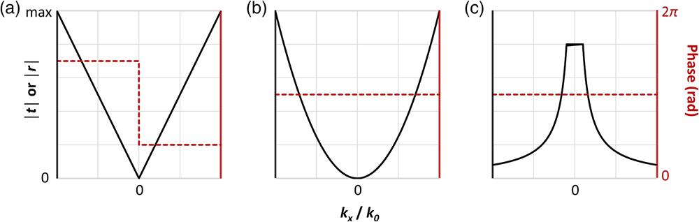
    Fig. 1. Required optical transfer functions for all-optical calculations for (a) first- and (b) second-order differentiation and (c) integration. The black lines represent the required transmission or reflection coefficients, whereas the red dashed lines denote the required phase. Note the π phase shift required at kx/k0 for the first-order differentiation, due to its being an odd function. The absolute value of the phase is arbitrary. The limits of the x axis are determined by the angular response of the designed metamaterial, which denotes the working NA of the system. Note the arbitrary truncated region around 0 for the integration operation that is necessary to avoid unphysical gain requirements, as suggested in Ref. 13.
    All-optical calculations using planar films. (a) Experimentally measured (green dots) and numerically fitted (solid lines) spatial transfer functions for three different samples. θ0 corresponds to the incident angle required for the phase matching to support the SPP. All optical first-order differentiation of (b) (i) amplitude and (c) (i) phase images. (ii) The reflected intensity after differentiation. Scale bars, 100 μm. (d) Calculated reflectance for p-polarization (solid line) and s-polarization (dashed line) at the absorption wavelength of 631 nm. (e) Demonstration of edge enhancement in reflected amplitude images. (i) Bright-field microscope image of the amplitude object and experimentally reflected image from the thin film mirror at (ii) 598 nm, (iii) 640 nm, and (iv) 694 nm. Scale bar, 100 μm. (f) Experimental demonstration of phase imaging of a biological sample. Images reflected from the mirror at (i) 598 nm (ii), 638 nm, and (iii) 694 nm. Scale bar, 250 μm. First-order differentiation using the SHE of light. (g) Experimental (dots), theoretical (dashed lines), and the ideal (solid lines) spatial spectral transfer functions for first-order differentiation. (h) Experimental demonstration of the material and angle independence of SPE of light for image differentiation; (i) air to glass interface with the Chinese character for “light” and (ii) air to Au and glass interface with the English word “LIGHT.” Images (a)–(c) reproduced with permission from Ref. 23. Copyright 2017 Springer Nature Group. Images (d)–(f) reproduced with permission from Ref. 24. Copyright 2019 AIP Publishing LLC. Images (h)–(j) reproduced with permission from Ref. 25. Copyright 2019 American Physical Society.
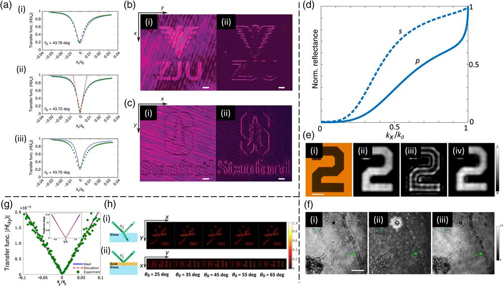
    Fig. 2. All-optical calculations using planar films. (a) Experimentally measured (green dots) and numerically fitted (solid lines) spatial transfer functions for three different samples. θ0 corresponds to the incident angle required for the phase matching to support the SPP. All optical first-order differentiation of (b) (i) amplitude and (c) (i) phase images. (ii) The reflected intensity after differentiation. Scale bars, 100  μm. (d) Calculated reflectance for p-polarization (solid line) and s-polarization (dashed line) at the absorption wavelength of 631 nm. (e) Demonstration of edge enhancement in reflected amplitude images. (i) Bright-field microscope image of the amplitude object and experimentally reflected image from the thin film mirror at (ii) 598 nm, (iii) 640 nm, and (iv) 694 nm. Scale bar, 100  μm. (f) Experimental demonstration of phase imaging of a biological sample. Images reflected from the mirror at (i) 598 nm (ii), 638 nm, and (iii) 694 nm. Scale bar, 250  μm. First-order differentiation using the SHE of light. (g) Experimental (dots), theoretical (dashed lines), and the ideal (solid lines) spatial spectral transfer functions for first-order differentiation. (h) Experimental demonstration of the material and angle independence of SPE of light for image differentiation; (i) air to glass interface with the Chinese character for “light” and (ii) air to Au and glass interface with the English word “LIGHT.” Images (a)–(c) reproduced with permission from Ref. 23. Copyright 2017 Springer Nature Group. Images (d)–(f) reproduced with permission from Ref. 24. Copyright 2019 AIP Publishing LLC. Images (h)–(j) reproduced with permission from Ref. 25. Copyright 2019 American Physical Society.
    Plasmonic-based metamaterials for all-optical calculations. (a) (i) Reflection coefficient and (ii) meta-atom dimensions for 50 μm wide plasmonic differentiator and integrator metasurfaces. (d=2.5 μm). (b) Bright-field images and measured (solid lines) average normalized reflectivity along the x coordinate, along with the ideal (dashed lines) reflectivity of the (i) differentiator and (ii) integrator plasmonic metasurfaces. (c) (i) Input object with varied phase and amplitude and (ii) reflected image after integration by the plasmonic metasurface, along with the measured (solid lines) and ideal (dashed lines) normalized intensity along the x direction. (d) Scattered intensities of the plasmonic circuits for first- and second-order differentiations as functions of incidence angle θ for a plane wave polarized along the meta-atoms. The inset indicates the oblique incidence for the second-order differentiation circuit. (e) Simulated transmission amplitude and phase of the 25 designed meta-atoms at 10 GHz. (f) Schematics, numerical simulations, and experimental results of the normalized electric field intensity distribution at the focal length of 100 mm and working frequency of 10 GHz for (i) 1D-edge detection along the x axis, (ii) 2D-edge detection, and (iii) 2D-edge detection of a regular hexagon. Images (a)–(c) reproduced with permission from Ref. 37. Copyright 2015 American Chemical Society. Image (d) reproduced with permission Ref. 38. Copyright 2018 Optica Publishing Group. Images (e) and (f) reproduced with permission from Ref. 39. Copyright 2022 Springer Nature Group.
    Fig. 3. Plasmonic-based metamaterials for all-optical calculations. (a) (i) Reflection coefficient and (ii) meta-atom dimensions for 50  μm wide plasmonic differentiator and integrator metasurfaces. (d=2.5  μm). (b) Bright-field images and measured (solid lines) average normalized reflectivity along the x coordinate, along with the ideal (dashed lines) reflectivity of the (i) differentiator and (ii) integrator plasmonic metasurfaces. (c) (i) Input object with varied phase and amplitude and (ii) reflected image after integration by the plasmonic metasurface, along with the measured (solid lines) and ideal (dashed lines) normalized intensity along the x direction. (d) Scattered intensities of the plasmonic circuits for first- and second-order differentiations as functions of incidence angle θ for a plane wave polarized along the meta-atoms. The inset indicates the oblique incidence for the second-order differentiation circuit. (e) Simulated transmission amplitude and phase of the 25 designed meta-atoms at 10  GHz. (f) Schematics, numerical simulations, and experimental results of the normalized electric field intensity distribution at the focal length of 100 mm and working frequency of 10  GHz for (i) 1D-edge detection along the x axis, (ii) 2D-edge detection, and (iii) 2D-edge detection of a regular hexagon. Images (a)–(c) reproduced with permission from Ref. 37. Copyright 2015 American Chemical Society. Image (d) reproduced with permission Ref. 38. Copyright 2018 Optica Publishing Group. Images (e) and (f) reproduced with permission from Ref. 39. Copyright 2022 Springer Nature Group.
    All-dielectric metamaterials for all-optical calculations. (a) Calculated optical transfer function for p-polarization at 1120 nm (red and green lines) and quadratic fitting (blue dashed line). (b) (i) Optical image of the 3D macroscopic imaging target of a plastic flower and its bright-field and differentiated imaging results. (ii) The same with a second target. (c) Imaging results for (i) bright-field and (ii) differentiated onion cells. Scale bars: 50 μm. (iii) Optical image of the compound metalens and differentiator system. (d) Simulated angular dispersion of the metasurface at different incident angles at the wavelength of 1400 nm, corresponding to the magnetic resonance mode. (e) Edge detection using the magnetic dipole mode at 1400 nm for horizontal and vertical stripes. (f) (i) Calculated (lines) and experimental (dots) amplitude of the meta-atoms and (ii) phase determined by the rotation angle of the meta-atoms. (g) (i) Amplitude object and (ii) differentiated images. Scale bars: 50 μm. (h) (i) The transmitted and (iii) differentiated images of a phase object. Scale bars: 50 μm. Images (a)–(c) reproduced with permission from Ref. 46. Copyright 2020 Springer Nature Group. Images (d) and (e) reproduced with permission from Ref. 47. Copyright 2021 American Chemical Society. Images (f)–(h) reproduced with permission from Ref. 48. Copyright 2022 Springer Nature Group.
    Fig. 4. All-dielectric metamaterials for all-optical calculations. (a) Calculated optical transfer function for p-polarization at 1120 nm (red and green lines) and quadratic fitting (blue dashed line). (b) (i) Optical image of the 3D macroscopic imaging target of a plastic flower and its bright-field and differentiated imaging results. (ii) The same with a second target. (c) Imaging results for (i) bright-field and (ii) differentiated onion cells. Scale bars: 50  μm. (iii) Optical image of the compound metalens and differentiator system. (d) Simulated angular dispersion of the metasurface at different incident angles at the wavelength of 1400 nm, corresponding to the magnetic resonance mode. (e) Edge detection using the magnetic dipole mode at 1400 nm for horizontal and vertical stripes. (f) (i) Calculated (lines) and experimental (dots) amplitude of the meta-atoms and (ii) phase determined by the rotation angle of the meta-atoms. (g) (i) Amplitude object and (ii) differentiated images. Scale bars: 50  μm. (h) (i) The transmitted and (iii) differentiated images of a phase object. Scale bars: 50  μm. Images (a)–(c) reproduced with permission from Ref. 46. Copyright 2020 Springer Nature Group. Images (d) and (e) reproduced with permission from Ref. 47. Copyright 2021 American Chemical Society. Images (f)–(h) reproduced with permission from Ref. 48. Copyright 2022 Springer Nature Group.
    Multiplexed and tunable metamaterials for all-optical calculations. (a) Calculated and experimental demonstrations of the two spin-dependent masking functions under 530 nm incidence. (i) The intensity distribution and (ii) phase profile of a Gaussian beam for LCP incidence, and (iii) donut-shaped intensity distribution and (iv) spiral phase profile for a 1ℏ OAM beam for RCP incidence. (v) and (vii) show measured nonparaxial interference patterns with a plane wavefront and (vi) and (viii) show the output states corresponding to LCP and RCP incidence. Insets, handedness of the incident light. (b) Images of undyed onion epidermal cells with a 20× objective lens. (i)–(iv) Bright-field images captured with LCP incident light at the wavelengths of 480, 530, 580, and 630 nm. (v)–(viii) Spiral phase contrast images captured under RCP incidence at the same wavelengths. Scale bar, 100 μm. (c) Schematic of the strain tunable metasurface under (i) no strain and (ii) 36% strain, along with the corresponding calculated transfer functions at the working wavelength of 1230 nm. (d) Experimental demonstration of the switchable image properties for (i) a sample of onion cells and (ii) an amplitude object of the number “2.” Images (a) and (b) reproduced with permission from Ref. 87. Copyright 2020 American Chemical Society. Images (c) and (d) reproduced with permission from Ref. 88. Copyright 2021 American Chemical Society.
    Fig. 5. Multiplexed and tunable metamaterials for all-optical calculations. (a) Calculated and experimental demonstrations of the two spin-dependent masking functions under 530 nm incidence. (i) The intensity distribution and (ii) phase profile of a Gaussian beam for LCP incidence, and (iii) donut-shaped intensity distribution and (iv) spiral phase profile for a 1ℏ OAM beam for RCP incidence. (v) and (vii) show measured nonparaxial interference patterns with a plane wavefront and (vi) and (viii) show the output states corresponding to LCP and RCP incidence. Insets, handedness of the incident light. (b) Images of undyed onion epidermal cells with a 20× objective lens. (i)–(iv) Bright-field images captured with LCP incident light at the wavelengths of 480, 530, 580, and 630 nm. (v)–(viii) Spiral phase contrast images captured under RCP incidence at the same wavelengths. Scale bar, 100  μm. (c) Schematic of the strain tunable metasurface under (i) no strain and (ii) 36% strain, along with the corresponding calculated transfer functions at the working wavelength of 1230 nm. (d) Experimental demonstration of the switchable image properties for (i) a sample of onion cells and (ii) an amplitude object of the number “2.” Images (a) and (b) reproduced with permission from Ref. 87. Copyright 2020 American Chemical Society. Images (c) and (d) reproduced with permission from Ref. 88. Copyright 2021 American Chemical Society.
    Machine learning using all-optical neural networks. (a) Comparison of the correspondence between ANNs and ONNs. The ANN is made up of neurons and hidden layers, which relate to the physical meta-atoms and cascaded metasurfaces in ONNs. (b) The coordinate system required to design ONNs using diffraction.
    Fig. 6. Machine learning using all-optical neural networks. (a) Comparison of the correspondence between ANNs and ONNs. The ANN is made up of neurons and hidden layers, which relate to the physical meta-atoms and cascaded metasurfaces in ONNs. (b) The coordinate system required to design ONNs using diffraction.
    Utilization of metasurfaces for ONNs. (a) Schematic of the input mask layer, showing the logic operation of “1 + 0.” (b) Amplitude and phase response of the dielectric meta-atoms. (c) Experimental setup of the two cascaded metasurfaces. (d) Distribution of the measured normalized intensity of the EM field. Most of the energy is focused to the region denoted for 0 or 1. (e), (f) ONNs for image classification and imager. (e) Schematic of the (i) MNIST data set classification and (ii) imager. (f) (i) An example of an input image expressed in phase and (ii) the output energy distribution. (iii) Confusion matrices and (iv) energy distribution percentages for experimental and numerical results of the fashion data set. (g) On-chip ONN working at visible wavelengths for image classification tasks using (i) MNIST and (ii) fashion data sets for x and y polarized light, respectively. (h) The confusion matrices for the (i) MNIST and (ii) fashion data sets for 80 randomly selected images. Images (a)–(d) reproduced with permission from Ref. 108. Copyright 2020 Springer Nature Group. Images (e) and (f) reproduced with permission from Ref. 118. Copyright 2018 The American Association for Advancement of Science. Images (g) and (h) reproduced with permission from Ref. 119. Copyright 2022 Springer Nature Group.
    Fig. 7. Utilization of metasurfaces for ONNs. (a) Schematic of the input mask layer, showing the logic operation of “1 + 0.” (b) Amplitude and phase response of the dielectric meta-atoms. (c) Experimental setup of the two cascaded metasurfaces. (d) Distribution of the measured normalized intensity of the EM field. Most of the energy is focused to the region denoted for 0 or 1. (e), (f) ONNs for image classification and imager. (e) Schematic of the (i) MNIST data set classification and (ii) imager. (f) (i) An example of an input image expressed in phase and (ii) the output energy distribution. (iii) Confusion matrices and (iv) energy distribution percentages for experimental and numerical results of the fashion data set. (g) On-chip ONN working at visible wavelengths for image classification tasks using (i) MNIST and (ii) fashion data sets for x and y polarized light, respectively. (h) The confusion matrices for the (i) MNIST and (ii) fashion data sets for 80 randomly selected images. Images (a)–(d) reproduced with permission from Ref. 108. Copyright 2020 Springer Nature Group. Images (e) and (f) reproduced with permission from Ref. 118. Copyright 2018 The American Association for Advancement of Science. Images (g) and (h) reproduced with permission from Ref. 119. Copyright 2022 Springer Nature Group.
    Programmable metasurfaces for ONNs. (a) Optical images and reconstructions from the single-layer programmable metasurface. Experimental demonstrations of (b) image classification between the letter “I” and square brackets, (c) simultaneous transmission of four orthogonal codes, and (d) on-site reinforcement learning using the programmable five-layer ONN. Image (a) reproduced with permission from Ref. 131. Copyright 2022 Springer Nature Group. Images (b)–(d) reproduced with permission from Ref. 132. Copyright 2022 Springer Nature Group.
    Fig. 8. Programmable metasurfaces for ONNs. (a) Optical images and reconstructions from the single-layer programmable metasurface. Experimental demonstrations of (b) image classification between the letter “I” and square brackets, (c) simultaneous transmission of four orthogonal codes, and (d) on-site reinforcement learning using the programmable five-layer ONN. Image (a) reproduced with permission from Ref. 131. Copyright 2022 Springer Nature Group. Images (b)–(d) reproduced with permission from Ref. 132. Copyright 2022 Springer Nature Group.
    Trevon Badloe, Seokho Lee, Junsuk Rho. Computation at the speed of light: metamaterials for all-optical calculations and neural networks[J]. Advanced Photonics, 2022, 4(6): 064002
    Download Citation