
Hongda WANG, Qian FENG, Xiao YOU, Haijun ZHOU, Jianbao HU, Yanmei KAN, Xiaowu CHEN, Shaoming DONG. Microstructure and Corrosion Behavior of Brazed Joints of SiC/SiC Composites and Hastelloy N Alloy Using Cu-Ni Alloy [J]. Journal of Inorganic Materials, 2022, 37(4): 452
- Journal of Inorganic Materials
- Vol. 37, Issue 4, 452 (2022)
Abstract
Ceramic matrix composite is a kind of excellent material for extreme service environment application[1-2]. Among this kind of material, SiC fibers reinforced SiC ceramic matrix composites (i.e. SiC/SiC composites) have been applied in critical structural applications because of their outstanding oxidation resistance property[3] and superior high-temperature mechanical properties[4-5]. More recently, the SiC/SiC composites have been considered as one of the ideal candidate structure materials for the Molten Salt Reactor (MSR) and the Advanced High Temperature Reactor (AHTR), owing to their good irradiation-resistance property[6-7], the compatibility to liquid fluoride salt[8⇓⇓-11], and low activity[12]. Control rod, tie bar, fuel cladding and sleeve in the fuel assembly, the heat exchanger and the coolant loop in MSR and AHTR[13] can be made of SiC/SiC composites. Most of such applications above in reactors require SiC/SiC composites to join alloy materials, such as Hastelloy N alloy, a kind of Ni-based alloy with good corrosion resistance to fluoride salt, or SiC/SiC composites themselves.
The joint of SiC/SiC composites for nuclear energy systems has some special requirements, e.g., hermeticity, high-temperature mechanical property and good compatibility to the working medium. The joining of SiC/SiC composites for fusion reactor has been developed via using SiC-based preceramic polymer, for example, methyl-hydroxyl-siloxane and polyhydrido-methyl-siloxane (PHMS)[14], which transforms into ceramics when being pyrolyzed at high temperature, yielding an adhesive bonding with SiC-based materials. Slurry composed of preceramic polymer and solid powders, like SiC, has also been utilized to prepare ceramic joint of SiC/SiC composites. However, the joint of SiC/SiC composites to alloy for application in salt-cooled nuclear energy systems has rarely been reported.
Compared with mechanical joining, diffusion bonding, and reaction forming, brazing requires lower temperature with less influence on joined materials and could obtain dense joint with good hermeticity[15]. Active metal brazing is a simple and cost-effective technique to join ceramics to metal. Ni-based[16], Ag-based[17-18], Co-based[19] and some other filler metals have been developed to brazing SiC/SiC composites to alloys. Most of these researches focus on the wetting ability of brazing filler metal on SiC composites and the improvement of mechanical properties of joint at service temperature. Therefore, few study concentrates on the corrosion resistance performance of the joint of SiC/SiC composites to alloys, especially in the high-temperature molten fluoride salt environment.
Cu-Ni binary alloy has been applied as the inert anode in electrolysis cell with an electrolyte composed of cryolite, aluminum fluoride, magnesium fluoride, and so on[20]. This suggests the good corrosion resistance of Cu-Ni alloy to fluoride salt. Moreover, although Cu is non- wetting on the SiC, Ni could react with SiC at high temperature[21], which means that Ni may play the role of active metal during the brazing process.
In this work, Cu-2.67Ni binary alloy was used to join SiC/SiC composites to the Hastelloy N alloy. The influence of brazing temperature on the joint microstructure was studied, and the corrosion behavior of obtained joint was also analyzed.
1 Experimental procedure
1.1 Materials
The composites used in this work were two-dimensional woven fabrics of KD-II SiC fibers (National University of Defense Technology, China) reinforced SiC ceramic matrix composites. The SiC/SiC composites were prepared via chemical vapor infiltration (CVI) processing, using the methyltrichlorosilane as raw material and H2 as the carrier gas. In advance of the CVI processing, a pyrolytic carbon (PyC) monolayer about 100 nm in thickness was deposited on the surface of SiC fibers through chemical vapor deposition (CVD). The SiC/SiC composites were cut into 8 mm×5 mm×2 mm pieces. The Ni-based superalloy, Hastelloy N alloy, with a nominal mass composition of 68.77% Ni, 18.90% Mo, 7.01% Cr, 4.18% Fe, 0.41% Si, 0.47% Mn, and 0.26%Al, was provided by Institute of Metal Research, Chinese Academy of Sciences. The Hastelloy N alloy bulk was sectioned into 10 mm×10 mm×5 mm blocks. All materials were cleaned by acetone in an ultrasonic cleaner and then dried in a vacuum drying chamber for the brazing experiment.
The Cu powders (99.7%, 80 μm (200 mesh)) and Ni powders (99.5%, 80 μm (200 mesh)) were obtained from Sinopharm Chemical Reagent Co., Ltd. According to the Cu-Ni binary system diagram[22], the continuous solid solution with FCC structure is in all ranges of composition. Considering the deterioration of SiC/SiC composites over high temperature[23], brazing temperature should be as lower as possible, which meant that the content of Ni would be small. On the other hand, Ni was employed as the reactive metal to improve the wettability, indicating that enough Ni should be contained. Based on the requirements above, brazing alloy composed of 97.12Cu- 2.88Ni (in atom fraction), or 97.33Cu-2.67Ni (in weight fraction) was chosen to braze the SiC/SiC composites to Hastelloy N alloy. In addition, a solution of polyvinyl butyral (PVB) in cyclohexanone, with a concentration of 3%-5% (mass percentage), was introduced as the binder to prepare the brazing paste.
1.2 Brazing experiment
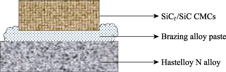
The joining process of SiC/SiC composites to Hastelloy N alloy was as follows: Firstly, Cu powders and Ni powders weighted in the desired composition were mixed mechanically with binder in an agate mortar to prepare a brazing paste. Secondly, the paste was brushed onto the surfaces of both SiC/SiC composites (parallel to the fiber fabrics) and Hastelloy N alloy. Then the composites pieces were stacked on the alloy blocks face-to-face to form a sandwich-like structure (as shown in Fig. 1). After drying, the assembly was put into the vacuum furnace and heated to 1090, 1110, 1130, and 1150 ℃ at a rate of 10 ℃/min for 10 min, respectively. During the cooling of furnace, a cooling rate of 10 ℃/min was controlled above 500 ℃, then followed by natural cooling to room temperature.
![]()
Figure 1.Schematic illustration of the sandwich-like structure of joint
1.3 Corrosion experiment
After brazing, the obtained brazing joint of SiC/SiC composites to Hastelloy N alloy was dipped into the 50 g 46.5LiF-11.5NaF-42.0KF (mole fraction, FLiNaK) eutectic fluoride salt (Shanghai Institute of Organic Chemistry, Chinese Academy of Sciences) contained in the graphite crucible. Following, the crucible was heated at 800 ℃ in the furnace for 100 h. Here, it should be mentioned that all above operations were conducted in a glove box under the protection of high purity argon gas. The atmosphere in the glove box was controlled at O2 < 10-5% (in volume) and moisture < 10-5% (in volume) in the corrosion process. After the high-temperature corrosion process in molten fluoride salt, the joint samples were picked out from the crucible and immersed into 1 mol/L Al(NO3)3 solution to remove the fluoride salt solid adhering on the sample surfaces and penetrating into the inside[24]. Finally, the samples were cleaned by ultrasonication in deionized water, then dried in a vacuum drying chamber.
1.4 Characterization
The obtained brazing joint samples before and after corrosion were cut along the direction perpendicular to the brazing plane to expose the cross-section. Then the cross-sections were polished and ultrasonically cleaned in acetone. The scanning electron microscope (SEM, Quanta-250, FEI, USA) coupled with energy dispersive spectrometer (EDS, Oxford, UK) was employed to characterize the microstructure and distribution of elements in joint samples. The inductively coupled plasma atomic emission spectrometry (ICP-AES, Vista AX, VARIAN, USA) was used to analyze the impurity composition in fluoride salt before and after the corrosion process.
2 Results and discussion
2.1 Microstructure of brazing joints
The joints of SiC/SiC composites to Hastelloy N alloy were obtained at 1090-1130 ℃, while no joint was obtained at 1150 ℃ because of the damage of SiC composites. The microstructure of joints evolution of SiC/SiC composites to Hastelloy N alloy at varying temperatures is shown in Fig. 2. When brazed at 1090 and 1110 ℃, voids (pointed by a red ellipse in Fig. 2(a) and black arrows in Fig. 2(b)) existed in the brazing alloy because of the incomplete fusion of brazing powders and poor fluidity of liquid metal. When brazed at 1130 ℃, the dense joint, which was well-bonded to both SiC/SiC composites and Hastelloy N alloy and devoid of imperfections, such as cracks and voids, was obtained. The thickness of the brazed seam was ~200 μm. The elemental mappings of the joint obtained at 1130 ℃ shown in Fig. 3 indicated that elements in the Hastelloy N alloy, e.g. Ni, Mo, and Cr, diffused into the seam area. Cu and Ni diffused into the composites, while Si element moved into the weld area. Both Ni and Cr elements are enriched at the interface between SiC/SiC composites and seam, indicating their reactions with SiC. High magnification image (Fig. 2(d)) of a blue rectangular area in Fig. 2(c) showed the detail of reaction area between SiC and brazed seam. The gray reaction layer was observed. According to the EDS results (Fig. 2(e)), the gray layer (point 1 in Fig. 2(d)) mainly consisted of Cr and C and would be the product of the reaction between Cr and SiC. The C-rich area (point 4) and the Ni-Si area (point 3) were observed. Furthermore, when the temperature increases to 1150 ℃, over diffusion and reaction between diffused metal and SiC at SiC/SiC composites side happened, which led to the failure of forming joint.
![]()
Figure 2.SEM images of brazing joints obtained at (a) 1090, (b) 1110 ℃, (c) and (d) 1130 ℃, correspoding EDS analyses (atom fraction) (e) of the point in image (d)
![]()
Figure 3.Elemental distribution analyses by EDS of joint obtained at 1130 ℃
Compared with Ni, the designed active element in brazing filler, Cr plays the role of the active element in brazing alloy more frequently, for instance, the PdNi-Cr-V alloy[25]. According to Park, et al[21], Cr is one of the type II elements, while Ni belongs to the type I metal. The products of the reaction between Cr and SiC are chromium carbides and chromium silicides, while Ni reacts with SiC to form nickel silicides and graphite. The thermodynamic calculation results shown in Fig. 4 reveal that the formation of reaction products is in order of Cr23C6, Cr7C3, Ni2Si, Cr3C2, and Cr3Si, which suggests that Cr has higher activity than Ni from 950 ℃ to 1150 ℃ and could react with SiC much easilier. This may be the reason that Cr acted as the active element and enriched at the interlayer area in the brazing process.
![]()
Figure 4.Gibbs free energy of formation of candidates calculated using HSC Chemistry 5.11 computer software and its associated databases
Microstructure of the over diffusion area in SiC composites obtained at 1150 ℃ and the EDS line-scan analyses are shown in Fig. 5. Three sections were observed in the reaction zone in composites in Fig. 5(a), the porous structure (Section I), the light gray area with cracks (Section II) and the dark gray (Section III). Line-scan analysis results in Fig. 5(c-e) showed that the light gray diffusion area was mainly composed of Ni and C with a little Si, while the dark gray area was the SiC fibers and CVI SiC matrix, which implied that the Ni diffused from the filler and Hastelloy N alloy reacted with SiC fibers and CVI matrix seriously during the brazing at 1150 ℃. From section I to section III, the closer the section was to the brazing filler, the more serious the reaction damage would be.
![]()
Figure 5.SEM image of microstructure and EDS line-scan analyses in SiC/SiC composites near joint obtained at 1150 ℃
XRD pattern of the brazed seam before and after corrosion is shown in Fig. 6. Particularly, the brazed seam pattern is obtained near the interface between the SiC/ SiC composites and the seam. The major phase of the joint seam is Cu0.81Ni0.19, which is formed by alloying of Cu and Ni. Meanwhile, the peaks of Cr23C6, Ni and Ni2Si can be detected. It is concluded that Cr23C6 is the product of the diffused Cr and SiC or C, which coincides with the EDS mapping and the thermodynamic calculation results. The appearance of Ni2Si is blamed for the reaction between Ni and SiC, which can be seen in Fig. 5. Moreover, Cr from Hastelloy N alloy and Ni is bound to react with SiC in the brazing progress. Considering the distribution of Cr and Ni, Cr plays the role of active metal other than the Ni element. The detection of Ni might be the residual Ni introduced by brazing metal powders.
![]()
Figure 6.XRD patterns of joints before and after corrosion
2.2 Corrosion behavior
The microstructure of joint obtained at 1130 ℃ before and after corrosion at 800 ℃ for 100 h are shown in Fig. 7. The elemental mapping results of the corroded joint are shown in Fig. 8. Compared with the microstructure of joint before corrosion, the microstructure of corroded joint contained holes in both brazing seam and Hastelloy N alloy, and the interlayer between SiC/SiC composites and the joint seam was replaced by crack. Cr loss was observed in the corresponding area in EDS mapping results, meanwhile, the ICP-AES results shown in Table 1 gave the evidence of the Cr loss from the joint because of higher Cr content after corrosion than that before corrosion. In addition, there was a little Si in seam shown in the EDS mapping result in Fig. 8. These indicated that the corrosion of joint seam and alloy might be caused by the optional corrosion of diffused Cr and Si. Liquid salt infiltrated into the seam through the holes to erode the Cr-contained interlayer, which was confirmed by the disappearance of Cr-rich interlayer in the elemental mapping results and leaded to the appearance of cracks in Fig. 8.
![]()
Figure 7.Appearance images and SEM images of microstructure of joints before and after corrosion at 800 ℃ for 100 h
![]()
Figure 8.Elemental distribution analyses by EDS of joint obtained at 1130 ℃ after corrosion at 800 ℃ for 100 h
| Element | Before corrosion | After corrosion |
|---|---|---|
| Ni | 10 | 20 |
| Cr | 20 | 210 |
| Fe | 30 | 40 |
| Mo | <10 | <10 |
Table 1.
Content of main metal impurities in fluoride salts before and after corrosion (10-4% in mass)
On the other aspect, the red XRD pattern of the corroded joint presented in Fig. 6 shows that the phase composition changed during the corrosion. The peak of Cr23C6 disappeared, while the Cu0.81Ni0.19, SiC/SiC composites, and Ni2Si still remained. It is concluded that fluoride salt corrodes the Cr-contained phase selectively. That is to say, the well-bonded reaction interlayer should have good compatibility with fluoride salt at high temperature.
Cr in Hastelloy N alloy has worse corrosion resistance to molten fluoride salt, and would be corroded and dissolved selectively[26], while Si has the compatibility problem with liquid fluoride salt, which has been discussed by Schmidt, et al.[27] This explains the corrosion of joint seam and alloy. However, the selective corrosion of Cr in Hastelloy N alloy is much slower than that shown in this experiment. The change of composition and microstructure of alloy should be blamed for the worse corrosion. As discussed above, Cr from the alloy plays the role of active metal in the brazing process. The diffusion of Ni, Cr from alloy to brazing alloy, and the diffusion of Cu into alloy changed the composition and microstructure of Hastelloy N alloy, resulting in more serious degradation of corrosion resistance performance.
According to Sellers, et al.[28], H2O impurity contained in FLiNaK would produce HF:
HF would react preferentially with Cr:
Because of the graphite crucible, the CrF2 (Cr2+) dissolved in the fluoride salt diffuses to graphite surface to form Cr7C3, which was reported by Ozeryanaya[29].
The formed CrF3 dissolved into the molten salt and diffused back to the corroded sample. In the joint corrosion processing, the CrF3 could contribute to both the alloy corrosion and the joint seam corrosion. The corrosion reaction of Cr in Hastelloy N alloy and joint seam caused by CrF3 (Cr3+) would be as follows[29]:
The formed CrF2 through reaction (5) dissolved into the liquid salt, diffused to the joint and accelerated the selective corrosion of Cr by reaction (4). That is to say, the brazing filler should not change the composition of the alloy or serve as the diffusion media for the alloy elements in order to keep the corrosion resistance of Hastelloy N alloy. On the other hand, the corrosion behavior of Cr-rich interlayer is still unknown, which should be further studied.
Because of the unique extremely environment, the brazing joint between SiC/SiC composites and Hastelloy N alloy for liquid fluoride salt environment needs to consider more specific facts. Based on the above experimental results, some roles can be drawn. On the one hand, the active composition and its reaction products should present good compatibility with liquid fluoride salt. On the other hand, to maintain the corrosion resistance property, the brazing materials should not change the composition and microstructure of Hastelloy N alloy. Therefore, for solving these two problems simultaneously, more efforts are needed to be paid on designing and seeking new suitable brazing filler materials system and finding bonded mechanism that meets these requirements.
3 Conclusion
Cu-2.67Ni (weight fraction) alloy was used to brazing SiC/SiC composites to Hastelloy N alloy. The sound joint was obtained at 1130 ℃ for 10 min. Lower brazing temperature leads to the appearance of holes because of the incomplete fusion metal powders and poor fluidity, while higher brazing temperature contributes to the over diffusion of Ni and the over reaction between Ni and SiC to form the brittle Ni-Si compounds, leading to the appearance of cracks and vesicular damaged area. Cr element from Hastelloy N alloy diffused into the joint seam and acted with SiC as active element together with Ni. In the corrosion process, Cr in joint seam and Hastelloy N alloy and Si in seam were selectively corroded. Serious Cr loss confirmed by the ICP-AES result suggests the unsatisfied corrosion resistance of Cu-2.67Ni joint of SiC/SiC composites and Hastelloy N alloy to FLiNaK molten salt.
References
[1] W KRENKEL. Ceramic Matrix Composites: Fiber Reinforced Ceramics and their Applications. Weinheim: John Wiley & Sons(2008).
[13] D F WILLIAMS, L M TOTH, K T CLARNO. ORNL/TM-2006/12. Oak Ridge: Oak Ridge National Lab.(2006).
[15] Y ZHANG, D FENG, Z Y HE et al. Progress in joining ceramics to metals. Journal of Iron and Steel Research, 13, 1-5(2006).
[20] J LU, Z XIA. The corrosion performance of a binary Cu-Ni Alloy used as an anode for aluminum electrolysis. Applied Mechanics & Materials, 55, 7-10(2011).
[22] P FRANKE, TZ D NEUSCH, Nickel//FRANKE P Cu-NiCopper-, TZ D NEUSCH. Cu-Ni(Copper- Nickel)//FRANKE P, NEUSCH TZ D. Binary systems Part 3: Binary Systems from Cs- K to Mg-Zr Heidelberg(2005).
[24] L C OLSON, J W AMBROSEK, K SRIDHARAN et al. Evaluation of Material Corrosion in Molten Fluoride Salt. Proceedings of the Presentation on AIChE Conference, San-Francisco, F(2006).
[28] R S SELLERS, W J CHENG, M H ANDERSON et al. Materials Corrosion in Molten LiF-NaF-KF Eutectic Salt under Different Reduction-oxidation Conditions. Proceedings of the International Conference Advances in Nuclear Power Plants (ICAPP’12), F(2012).


Set citation alerts for the article
Please enter your email address

© Copyright 2018-2021 | Chinese Laser Press. All Rights Reserved 沪ICP备15018463号-20