
Sarkar Tushar, Chandra Mandal Aditya, Ziyang Chen, Jixiong Pu, Kumar Singh Rakesh. Correlation Holography with A Single-Pixel Detector: A Review[J]. Laser & Optoelectronics Progress, 2021, 58(10): 1011011
- Laser & Optoelectronics Progress
- Vol. 58, Issue 10, 1011011 (2021)
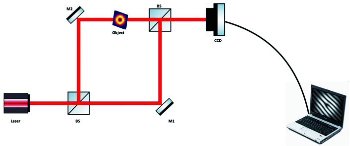
Fig. 1. A typical experimental geometry based on the Mach-Zehnder geometry for an off-axis holography system
![(a) Sketch of a cyclic lateral shearing interferometer, the arrows denote the central ray path; (b) sketch of the experimental arrangement for quantitative phase cyclic interferometer. The object is placed at one-half of the optical field of view (FOV). The interferometer section makes two laterally shifted and collinearly propagating non-collimating wavefronts for interference at the CCD plane. CCD: charged coupled device[86]](/richHtml/lop/2021/58/10/1011011/img_2.jpg)
Fig. 2. (a) Sketch of a cyclic lateral shearing interferometer, the arrows denote the central ray path; (b) sketch of the experimental arrangement for quantitative phase cyclic interferometer. The object is placed at one-half of the optical field of view (FOV). The interferometer section makes two laterally shifted and collinearly propagating non-collimating wavefronts for interference at the CCD plane. CCD: charged coupled device[86]
Fig. 3. Steps highlighting Fourier fringe analysis of the recorder hologram
Fig. 4. An experimental setup to record the polarization hologram. BS is a beam splitter, HWP is a half-wave plate, M is mirror, P is polarizer, QWP is a quarter-wave plate, CCD is charged coupled device [14]
Fig. 5. Recording process in the vectorial coherence holography. (a) Hologram of Ex component of the light coming from the object; (b) hologram of Ey component of the light emanating from the object. Two holograms are used to reconstruct desired images in the coherence-polarization matrix of a light field [68]
Fig. 6. Formation of orthogonally polarized holograms at the diffuser plane and reconstruction of these holograms by an incoherent light source. Instantaneous random fields at the observation plane, for two orthogonal polarization components, are represented by Ex(r2) and Ey(r2), and the random field is characterized by the coherence-polarization matrix W(r2,r2+Δr)
Fig. 7. Experimental scheme for intensity correlation holography[79]
Fig. 8. (a) Denotes intensity correlation holography scheme, S is a spatial filter, L is a lens, RG is rotating ground glass, T is transparency; (b) HCH with SPD setup, BS is a beam splitter, SLM is a spatial light modulator, P is a polarizer, c is a correlator, D is a single-pixel detector [79]
Fig. 9. A transparency, shown on the right-hand side, with 3D information of objects located at three different z planes [79]
Fig. 10. Reconstructed objects at three different longitudinal distances (z) from the focal planes [79]
Fig. 11. Change in reconstruction quality with an increasing number of random phases in the HCH
Fig. 12. (a) Coherence waves interference setup with the correlation of the intensity detected by a CCD, L is the lens, D is a pinhole, BS are beam splitter, M are mirrors, T is transparency, MO is microscope objective, RGG is rotating ground glass; (b) optical channel in the HCH with a single-pixel detector, BD is beam displacer, PBS is a polarization beam splitter, SLM is the spatial light modulator, CA is a circular aperture, c is correlator, D is single-pixel detector; (c) architecture for digital propagation of the random fields and correlation of single point intensity with two-dimensional propagated intensity[80]
Fig. 13. Recovery of the complex field in a single-pixel modified HCH approach for two different transparencies. Results for an off-axis hologram of the object “1” is used as a transparency, (a) cross-covariance of the intensities, (b) amplitude of the object, and (c) a phase of the object; a spiral phase plate is used complex transparency and results are (d) cross-covariance of the intensity, (e) amplitude of the vortex field, and (f) a phase of the vortex field. The interpolated portion of these results are shown in corner of each figure [80]

Set citation alerts for the article
Please enter your email address
© Copyright 2018-2021 | Chinese Laser Press. All Rights Reserved 沪ICP备15018463号-20