Abstract
Correlation holography uses incoherent light to reconstruct holograms. This technique reconstructs objects as distributions of two-point coherence function rather than using optical fields, as in conventional holography. The basic principle of correlation holography is derived from the van Cittert--Zernike theorem and relies on the similarity between the optical field and the coherence functions. Experimental implementation of the correlation holography techniques requires a field or intensity interferometer, and fringe analysis and cross-covariance measurement in these interferometers require a conventional camera with array detectors. With the availability of digitally controlled diffractive elements, it is possible to replace the incoherent light source, such as a rotating ground glass, with a digital source loaded with the random patterns in sequence. Such strategies ease the burden on the detector and allow for correlation holography with a single-pixel detector (SPD) to be used. This review paper discusses a close connection between digital holography and correlation holography. The principles of correlation holography with the SPD are reviewed in detail, and the advantages of using digital sources to mimic incoherent illumination in the correlation holography are examined in the context of three-dimensional and complex field imaging.1 Introduction
For over 70 years ago, holography has played an important role in non-destructive testing, quantitative imaging[1-12], and other applications. Holography works on the principle of recording the complex wavefront of the light diffracted from an object. The optically recorded interference pattern preserves the complex field of the object, in essence, containing a signature of the object. Diffraction of light from this interface pattern is referred to as a hologram. Three-dimensional (3D) information about the object can be reconstructed from the hologram and analyzed using the paraxial diffraction theory. Analysis of polarization features in a hologram offers a new dimension for the field of holography.
Lohman proposed using holography for polarized light by extracting the vector nature of the light’s wavefront[13]. Digital holography (DH) has been used in the vectorial domain through optical recording and numerical reconstruction of digital holograms from the orthogonal polarization components of coherent light[14-17]. Holography in the vectorial regime provides several promising applications ranging from metrology to bio-medical imaging. In recent years, attempts have also been made to develop holography with arbitrary coherence-polarization using the Stokes fringes rather than intensity fringes only[18-19]. Modulation and contrast of the Stokes fringes rely on the coherence-polarization of light[20].
The availability of array detectors and reconstruction algorithms has further revolutionized holography. Optical reconstruction of holograms has become supplanted by DH. This technique preserves unique features of a hologram, such as the complex amplitude distribution, and provides a simple reconstruction method[6]. Among various methods used to recover phase information, DH is a well-established technique for quantitative complex field imaging. Further, DH permits 3D imaging by numerically refocusing a two-dimensional (2D) image at different object planes without mechanical movement. Various DH techniques have been developed, significant among them being in-line[1], off-axis[2], and phase-shifting holography[5]. The most common approach to utilizing DH is based on off-axis geometry, wherein the object and reference beams travel in different optical paths before being recorded by a camera[2].
A conventional detector with a large number of pixels candigitally capture an image of fine interference fringes, and a computer with high computational efficiency can numerically reconstruct a hologram from the captured image[6]. Availability of high-speed cameras and digital signal processing tools support DH techniques. Since the invention of the digital camera, higher resolution image retrieval has been a fast-growing research topic. For capturing a digital image, the development of complementary metal-oxide-semiconductor pixilated sensors and silicon-based charge-coupled devices (CCDs) has led to significant developments in photography. Modern cameras, ranging from digital single-lens reflex to smart phones, capture images by using a chip no larger than a fingernail, which contains millions of detector pixels. Although pixilated detectors have benefits, such as high performance, imaging sensors for the long-wavelength infrared or deep ultraviolet regions are either expensive or not widely available[21-24]. Pixel counts in camera sensors have reached over 20 million, bringing extra data storage problems in conventional applications. To solve these issues, a novel computational imaging method that can reconstruct an image with fewer measurements is needed. One such method is the single-pixel detector, which can provide a competitive advantage over traditional cameras. For instance, this technology requires only one light-sensitive detector, offering a cheaper alternative than its multi-pixilated counterpart[21].
Single-pixel imaging, presented by Duarte et al. [25], preceded the progress of compressive sensing. This groundbreaking invention was a synthesis of various imaging and sampling methods and laid the groundwork for retrieving images from a compressed sensing-assisted single-pixel detector (SPD). In 2005, Sen et al. obtained an image using only a single pixel rather than a conventional detector array via a technique known as dual photography[26]. Advantages of an SPD include the following: the development of a high-sensitivity and cost-effective imaging system in short-wave infrared and in X-ray imaging[21]; a suitable test platform for new, state-of-the-art image-capturing technologies, such as compressive radar [27]; fluorescence microscopy[28]; visible-near imaging[29-31]; terahertz imaging[32-34]; and other imaging and algorithmic applications[35-41].
Several correlation techniques have been proposed for imaging[33-57]. For instance, object information in ghost imaging is retrieved by observing photon coincidence or intensity correlations between two beams[46-47]. Two detectors are used in ghost imaging to conduct correlation measurements: one detects the non-interacted light field of the object to be reconstructed with high spatial resolution, and the other, known as a bucket detector, collects the interacted light field of the object. This was first demonstrated using the quantum source and later demonstrated with a classical incoherent (pseudothermal) light source[52]. Attempts have also been made to shift spatial sampling from the sensor and apply active illumination strategies using a programmable device, such as a spatial light modulator (SLM) or discrete micro-mirror device. The illumination pattern loaded on the SLM is projected onto the sample, and the whole intensity is collected by an SPD. Observations are done sequentially by varying the pattern of the SLM[47-49]. In contrast with most ghost imaging techniques, where the recovery of the amplitude is given priority, new schemes have also been developed to image the phase objects in ghost imaging[53-57]. Recently, we have introduced an off-axis holographic approach in the ghost diffraction scheme to get the complex field of the objects [57]. The ghost hologram can also be recorded with an SPD by importing the concept of the DH [51-52]. Several other experimental configurations have also been proposed to obtain the complex field using an SPD[53-56]. For example, Shin et al. [57] introduced an optical bidirectional transducer using an SLM, which provides a complex field using a single-point detector and phase conjugation scheme. Alternatively, Takeda et al. proposed an unconventional technique known as coherence holography (CH) [58-64].
Since these proposals, attempts have been made to develop various types of correlation holography for light structuring and imaging[65-75]. Correlation holography is composed of several unconventional holography techniques, such as CH[65], vectorial CH (VCH) [68], and photon correlation holography (PCH) [69]. In conventional holography, a hologram is used to record the complete wavefront, and subsequently, coherent light is used for the reconstruction of the hologram. Therefore, recording and reconstruction processes are completed using coherent light in conventional holography and the DH. However, in correlation holography, a coherently recorded hologram is used to synthesize the statistical features of light and image the objects as 3D distributions of the complex coherence function. A close analogy between conventional and correlation is attributed to a common link between the optical fields and the complex coherence function since both follow the wave equation. The correlation holography technique relies on the van Cittert--Zernike theorem, which provides a connection between the far-field correlation and incoherent hologram source structure based a Fourier transform[76-78].
Recently, we developed hybrid correlation holography (HCH) using an SPD to reconstruct 3D and complex-valued objects. Here, the hybrid provides a combination of optical and computational channels to image objects using an SPD[79-80]. Due to emerging interests in correlation imaging, this paper conducts survey on correlation holography. Special emphasis is given to correlation holography using an SPD. With the availability of SLMs, it is possible to replace classical light sources, such as a rotating ground glass (RGG), with a digital source loaded with the random patterns in sequence. This strategy can enable the development of correlation holography with the SPD.
This paper first introduces the concept of generalized holography and holography using an SPD. A comparison of DH and correlation holography is then made. The different architectures of correlation holography, such as CH, VCH, and PCH, are briefly discussed help understand HCH. After a detailed discussion about correlation holography, the possibility of replacing thermal light sources with a digital source is discussed in the context of the HCH using an SPD for 3D and complex field imaging.
2 Digital holography
DH is based on interferometry and can simultaneously provide amplitude and phase distributions of a target. In 1967, Goodman and Lawerence[3] showed that holograms are responsive to numerical reconstruction. The feasibility of the numerical reconstruction is attributed to the fact that the propagation of field is aptly described by the diffraction theory. In 1982, Takeda et al. [4] connected off-axis interferometry and fast Fourier transform and studied the topography of structures. This technique utilized CCDs as the detectors, leading to extensive research development in the field of the DH.
To explain the basic principle of the DH, we present a generalized framework with polarized light. A coherent optical field emerging from the object and reference is explained as
where Tm(r1) represents object transmittance function for the orthogonal polarization components of the light and m=x,y stands for the orthogonal polarization components. Subscript O and R indicate object and reference fields, respectively. The spatial coordinates at the source and the recording (hologram) plane are represented by r1 and r2, respectively. A complex field distribution at the recording plane is indicated as
Polarization fringesalong the recording plane are derived using Eq. (3) and are given as
where sn(r2), n=0--3 are the Stokes parameters of the recording plane and represent polarization[81]. The Stokes parameter s0(r2), which represents the intensity modulation, is usually applied in the holographic recording in the scalar case. Substitution of Eqs. (1) and (2) into Eq. (4) means that either combination of s0(r2) and s1(r2) or s2(r2) and s3(r2) is appropriate to retrieve the complex field of the fully coherent object.
Consider a situation where the polarization is either uniform or ignored. This situation corresponds to a well-established DH, where a recording of only intensity modulation, i.e., I(r2)=
and Ex(r2)=Ey(r2)=E(r2), is enough. Therefore, if the object O=EO(r2) is coherently superimposed with a known reference beam R=ER(r2), the hologram is described by a transmittance function t as
where the intensity of the object and reference fields are given by terms IO and IR. The complex field of the object is represented by
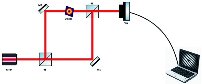
exp(iφ), and φ is spatial phase distribution. The reference field is represented as a beam with uniform amplitude and linear phase θR, i.e., R=exp(iθR). Phase extraction is possible from an off-axis geometry single hologram [2-4]. A reference beam can insert a phase shift to record the interference fringes. Such a method is also used to extract exp(iφ) by phase-shifting algorithms[5]. The most common approach for the realization of quantitative imaging is based on an off-axis approach, where object and reference beams propagate different paths. A typical experimental setup of the off-axis holography is shown in Fig. 1.

Figure 1.A typical experimental geometry based on the Mach-Zehnder geometry for an off-axis holography system
In some interferometric systems,the object and reference beams propagate the same path, which is known as common-path interferometry. Such experimental geometry is widely investigated to overcome the issue of stability of off-axis holography while maintaining its advantages[82-86]. In common-path geometry, the two beams travel through the object and almost follow the same optical path. Since both the wavefronts are derived from the same beam, they are immune to mechanical vibration and external disturbances. This technique generates high contrast fringes as the beam ratio, and the path length of the two beams are almost the same. An experimental setup developed by one of the authors for the common-path holography setup for the quantitative phase imaging is shown in Fig. 2[87]. This setup uses a cyclic lateral shearing approach, and an un-collimated coherent beam is used for illumination purposes, as shown in Fig. 2 (a). The corresponding experimental setup is shown in Fig. 2 (b). A monochromatic laser beam is collimated using the assembly of a spatial filter and collimating lens. To establish a generalized architecture, the collimation is slightly disturbed to gain a spherical wavefront. This beam illuminates the object, and the information-carrying beam is divided into two equal intensity beams at the beam splitter to traverse the triangular Sagnac geometry. Finally, a detector is inserted at a certain distance from the beam splitter (BS) to record the interference fringes.
Figure 2.(a) Sketch of a cyclic lateral shearing interferometer, the arrows denote the central ray path; (b) sketch of the experimental arrangement for quantitative phase cyclic interferometer. The object is placed at one-half of the optical field of view (FOV). The interferometer section makes two laterally shifted and collinearly propagating non-collimating wavefronts for interference at the CCD plane. CCD: charged coupled device[86]
A numerical algorithm based on Fourier fringe analysis is implemented to reconstruct the object information from the recorded hologram. The first two terms in Eq. (5) represent the DC component due to the irradiance of the individual object and reference field. The last two terms in Eq. (5) are the off-axis and spectrum terms in the frequency space, and these two terms are important to recover the complex field of the object. A digital 2D Fourier transform operation implemented on the recorded hologram separates various desired terms in the Fourier space. The numerical steps to process the hologram under the Fourier fringe analysis method are shown in Fig. 3. An appropriate filter to select the desired frequency spectrum helps to remove the unwanted terms in the frequency space and determines the reconstruction quality. We selected one of the off-axis frequency spectra, as shown in step 2 in Fig. 3, thereby suppressing the DC and avoiding the twin image issue. The selected spectrum is then shifted to the center, as shown in step 3, then a 2D inverse Fourier transform is implemented in step 4 to reconstruct the complex field information of the object at the CCD plane. The retrieved complex light field at the CCD plane is then numerically backpropagated to the object plane to represent the true complex amplitude structure.
Figure 3.Steps highlighting Fourier fringe analysis of the recorder hologram
3 Polarization digital holography
Polarization, together with the amplitude and phase, describes the complete optical field of the target object. Colomb et al.[14] proposed an experimental setup for digital polarization holography to map the spatial distribution of the polarization state of light emanating from an object. In this technique, a reference beam with two orthogonally polarization components interferes with the object beam to generate holograms for the orthogonal polarization components. As explained in the previous section, complete polarization mapping is possible by recording and reconstruction of only two holograms of the orthogonal polarization components for coherent light. An experimental configuration to record the polarization hologram is given in Fig. 4. This setup is specially designed to record two orthogonal polarization components simultaneously using polarization multiplexing. A modified Mach--Zehnder interferometer (MZI) uses two reference beams, R1 and R2. A coherent light then generates three interfering beams, R1, R2, and a birefringent object field O. A polarizer and quarter-wave plate are used tune the polarized light from the object, as shown in Fig. 4. The hologram is then recorded using off-axis geometry, with each reference beam traveling in different directions. This hologram is then digitally recorded and represented as
where O=
is the object field and R1=
and R2=
are the reference beams. Therefore, polarization multiplexing permits simultaneous recording and distinguishing of the orthogonal polarization components from the sample. The interference pattern recorded by the camera is subjected to numerical reconstruction. The methods for spatial frequency multiplex polarization interferometry and Fourier fringe analysis are applied to detect the complex light field of the orthogonal polarization components. Another off-axis method for polarimetric imaging was developed by Nomura et al.[15] Another highly stable and auto-calibrated experimental scheme was demonstrated for accurate spatial mapping of polarization states of light from a single hologram[87].
Figure 4.An experimental setup to record the polarization hologram. BS is a beam splitter, HWP is a half-wave plate, M is mirror, P is polarizer, QWP is a quarter-wave plate, CCD is charged coupled device [14]
4 Coherence holography: scalar to vectorial domains
Conventional holography records and reconstructsa 3D image as an optical field distribution. As mentioned, Takeda et al. developed CH[65]. This technique reconstructs the information of a 3D object as a distribution of the spatial coherence function. A coherent interference pattern is recorded and reconstructed via DH.
The recording process in coherence and CH is the same, but reconstruction is implemented using incoherent light illumination (rather than coherent). In CH (without polarization), a coherently recorded hologram is illuminated with incoherent light, and the object information is reconstructed as the distribution of the coherence function. Therefore, CH provides a 3D image as a spatial distribution of spatial correlation between a pair of points. An interferometer scheme is required to experimentally measure the spatial distribution of the complex coherence function. In the principle of CH, moving ground glass creates stationary quasi-ergodic time fluctuations, which grant one to supplant the ensemble average with time average, or integration time over the detector response time.
To provide a generalized principle of the correlation holography, we start our discussion with polarized light and consider CH as a special case where polarization is ignored. VCH is based on holograms for two orthogonal polarization complements, e.g., x and y. Fig. 5 displays a coherent recording of the field components, Ex and Ey, of an object, gx(r) and gy(r), separately in two Fourier transform holograms, Hx(r) and Hy(r). It is considered a polarized object and is composed of two numbers, 0 and 1, at the off-axis locations emitting, respectively, x- and y- polarized light with their Fourier spectra Gx(r) and Gx(r). Each of the holograms is illuminated with incoherent-polarized light, and the presence of two holograms for the orthogonal polarization components distinguishes this approach from CH[65].
To introduce the reconstruction of these holograms by an incoherent light source, a schematic representation of the reconstruction is shown in Fig. 6. The instantaneous complex field of the orthogonal polarization component at the RGG is represented as
where Hm(r1) is a fixed transmittance of the hologram and ϕm(r1,t) denotes a random phase introduced by the diffuser at a time t. The RGG in Fig. 6 is used to produce an incoherent illumination. The light emerging from the diffuser is optically Fourier transformed at the back focal plane of lens L2 with focal length f, and the instantaneous complex field at the focal plane is expressed as
Figure 5.Recording process in the vectorial coherence holography. (a) Hologram of Ex component of the light coming from the object; (b) hologram of Ey component of the light emanating from the object. Two holograms are used to reconstruct desired images in the coherence-polarization matrix of a light field [68]
Figure 6.Formation of orthogonally polarized holograms at the diffuser plane and reconstruction of these holograms by an incoherent light source. Instantaneous random fields at the observation plane, for two orthogonal polarization components, are represented by Ex(r2) and Ey(r2), and the random field is characterized by the coherence-polarization matrix W(r2,r2+Δr)
Characterization of the random light field is possible using a 2×2 coherence--polarization matrix. Under consideration of incoherent illumination, elements of the coherence--polarization matrix are represented as
Eq. (9) represents the connection between the incoherent source at the diffuser plane and the coherence function at the observation plane using a Fourier transform relation. The recorded object information in
is encoded into the coherence function through the van Citttert--Zernike theorem. For m=n, the situation leads to the CH. Experimental measurement of the complex coherence--polarization matrix requires an interferometer, and a detailed discussion can be found in the literature [65-68].
5 Intensity correlation holography
Significant progress and developments in correlation optics led to the emergence of numerous fundamental and practical applications. Important results in the coherence optics are the van Cittert--Zernike theorem and the Hanbury Brown and Twiss (HBT) approach. A correlation function of the fourth order, with respect to complex amplitude, is used in the HBT approach, and this approach became a preferred method to analyze random fields. The HBT approach makes use of the relationship between second-order and fourth-order Gaussian random fields. This provides a simple and stable experimental method to characterize the correlation parameters. The approach offered a novel insight into statistical optics and in the development of highly stable and unconventional imaging systems, such as astronomical imaging, PCH, and ghost diffraction. In early astronomical imaging, second-order correlation was widely applied for imaging astronomical objects. The HBT approach, based on intensity correlation, introduced a new direction in astronomical and unconventional imaging. Since the correlation is examined electronically after measurement of instantaneous intensities, the intensity correlations are rather simple and free from instability due to external disturbances.
A diagram for intensity correlation holography is shown in Fig. 7. Information of the 3D object is loaded into the coherently designed hologram, as explained earlier. However, a significant difference comes in the reconstruction process. In this section, we consider a scalar hologram (Hx=Hy).
Figure 7.Experimental scheme for intensity correlation holography[79]
In Fig. 7, E(r1;t) denotes the distribution of the field at the hologram plane at a spatial point r1 and time t, whereas H(r1)=Hx(r1)=Hy(r1) indicates the transmittance function of the hologram. The hologram is illuminated with an incoherent light from RGG. The instantaneous field generated at the Fourier plane is given by
Instantaneous intensity pattern is given as
and the cross-covariant of the intensity for the Gaussian random field is given as
where <ΔI(r2)>=I(r2)-<I(r2)> represents the fluctuation of intensities over its mean value.
Using relation of the complex coherence established in the previous section, the cross-covariance function becomes
Amplitude distributions of the object encoded into the hologram are reconstructed as a distribution of the cross-covariance function, and the phase information is lost. This differentiates PCH from CH and DH, which provides a complex coherence function or complex optical field distribution. Naik et al. [67] experimentally tested the idea of the PCH, and they compared the applicability of this technique in both temporal and spatial averaging. This technique provides a new dimension in correlation-based imaging.
6 Correlation holography with a single-pixel detector: HBT approach
Correlation imaging methods, such as ghost imaging, diffraction imaging, and intensity correlation holography, are based on the intensity correlation. The evaluation of photon coincidence or intensity correlation helps recover the object information in ghost imaging. Two photodetectors are used to realize correlation measurement: one detects the non-interacted light field of the object to be reconstructed with high spatial resolution, and the other, known as a bucket detector, collects the interacted light field of the object.
Computational ghost imaging with a bucket detector has also been proposed in recent years. In this method, randomness is inserted into a light beam in a controlled manner using a digital device and supplanted a conventional thermal source with the SLM assisted source. As a separate methodology, intensity correlation-based holography reconstructs the 3D structure of the amplitude object from the intensity correlations. This has been implemented using a connection between the cross-covariance and the second-order correlation of the Gaussian random fields, as shown in Eq. (13).
In a separate development, we developed an HCH technique using an SPD.This method can numerically reconstruct 3D objects by estimating the intensity correlations of an SPD and digitally propagated intensity patterns at the far-field planes. The SPD records the incoming light field after interaction with the object, and the light fields in the digital channel do not pass through the object. Here, hybrid reveals the combination of optical and computational channels. A comparison of intensity correlation holography and HCH is shown in Fig. 8. Fig. 8 (a) presents the basic principle of PCH for comparison purposes. A spatially filtered light beam through the spatial filter assembly S is expanded by lens L. The expanded plane wave is directed at the RGG, which generates a random pattern at a fixed time t. The incoming random pattern from the RGG passes through the transparency T, and subsequently, the random light travels toward the detector.
Figure 8.(a) Denotes intensity correlation holography scheme, S is a spatial filter, L is a lens, RG is rotating ground glass, T is transparency; (b) HCH with SPD setup, BS is a beam splitter, SLM is a spatial light modulator, P is a polarizer, c is a correlator, D is a single-pixel detector [79]
The recorded intensity pattern at the camera plane is given as
where F indicates a 2D Fourier transform, T(r1) represents transmittance (or reflectance) of the object at the RGG plane, and ϕ(r1) is the phase inserted by the diffuser. Note that the intensity at different z planes around the detector position can be observed using the paraxial propagation. The cross-covariance of the intensity can be expressed as
where parenthesis <·> denotes the ensemble average and the intensity fluctuation is ΔI(r2)=I(r2)-<I(r2)>. This equation states that transparency encodes the information and determines the intensity co-variance.
In HCH, a sequence of random phasesis introduced in the laser light to mimic an incoherent source using a computer-controlled spatial light modulator. An SPD is introduced in the optical channel. The digitally stored random phase is numerically propagated in the digital channel at z. Finally, the cross-covariance of the intensities from the two channels is determined. An experimental scheme for the HCH is represented in Fig. 8 (b). The basic principle, strategies, and results of the HCH are as follows.
A spatially filtered collimated coherent beam enters the BS. The beam reflected from BS illuminates the reflective type SLM, which loads the random phases into the laser beam. The light from the SLM reflects back and propagates through the BS and illuminates a transparency Tm(r1) for m=x,y polarization components. To generalize the principle for the vectorial case, we establish the theory for coherent polarized objects wherein consideration of two orthogonal polarization components is enough. The orthogonal components are obtained by incorporating the Jones matrix P(θ) of a polarizer as
where P(θ)=
is the Jones matrix of a linear polarizer oriented at θ with respect to the horizontal (x) direction. The intensity in the optical channel is
The intensity in the digital channel can be similarly represented. Therefore, the intensity correlation between the optical and digital channel, at orientation θ=0, is given as
where <·> indicates ensemble average. The intensity correlation for orientation of polarizer θ=π/2 is given as
Using the angular spectrum method for propagation from the source to the arbitrary observation plane in the digital channel, the second-order correlation from two channels is given as
Term Emo(0) represents the complex field at the SPD at the location (0,0). For the incoherent source, i.e., >=δ(r1-r'1), the field correlation becomes
where z is the propagation distance and kz=
. The wavelength of light is λ, and f is far-field distance. We can write the cross-covariance of the intensity as
Therefore, the 3D object is reconstructed as a distribution of the cross-covariance. As an example, consider a case of a scalar object, i.e., Tx(r1)=Ty(r1)=T(r1). Using propagation kernel and coherent beam propagation, 3D transparency placed at different distances can be considered, as shown in Fig. 9. Transparency for different objects placed at different longitudinal distances can be represented as
and is shown in Fig. 10 for objects located at different longitudinal planes.
Figure 9.A transparency, shown on the right-hand side, with 3D information of objects located at three different z planes [79]
Figure 10.Reconstructed objects at three different longitudinal distances (z) from the focal planes [79]
The production of HCH is described as follows. The SLM inserts a set of random phase structures ϕnl(M) into the laser on the nl pixel, where M stands for a total number of the random phases inserted by the SLM. These random phases appear to follow >=0 and >=δpnδql. The laser beam with the random phase illuminates the sample, and the field further travels toward the SPD. The random phase, loaded on the SLM, is also numerically propagated without transparency for the digital channel. The cross-covariance of the intensities is
The size of each random pattern displayed on the SLM is 400×400. The cross-covariance is estimated by correlating the intensities from two channels as explained earlier. A result of the cross-covariance for transparency is given in Fig. 10 (a)--(c), which denote reconstruction of the objects at three different z values with M = 400000, f = 500 mm, and λ=632.8nm. A virtual detector in the digital channel is digitally translated using digital propagation, and the corresponding numerically evaluated intensities at arbitrary z is correlated with the SPD intensity at z=0. Fig. 10 (a) reconstructed letter J at z=-200 mm from the focal plane, while the other two objects are longitudinally shifted. Results for z=0 and z=100 mm are presented in Fig. 10 (b) and 10 (c), respectively. The effect of varying M values on the reconstruction is shown in Fig. 11 for object “O” at z=0. The reconstruction improves with a higher value of M, as shown in Fig. 11. The spatial resolution is constrained by the cap of the delta correlation feature of the random phase pattern loaded by SLM. In this situation, the spatial resolution in HCH and CH relies on the spatial dimension of the transparency T and f-number of the Fourier transforming system as given in the experimental setup in Fig. 8, in which the increasing size of T to achieve high transverse resolution led to the reduction in the longitudinal resolution similar to DH.
Figure 11.Change in reconstruction quality with an increasing number of random phases in the HCH
7 Correlation holography with a single-pixel detector for complex field
Recently, we have developed a new technique to reconstruct the complex field within the HCH framework[80] in contrast to the application of the RGG in the phase recovery using the HBT approach[64] as shown in Fig. 12 (a). In the developed technique, random phases are introduced in the incident laser beam by an SLM, and the intensity in the optical channel is captured using an SPD. The geometry of the light propagation in the optical channel is shown in Fig. 12 (b). The beam displacer is used to make an incoming collimated beam into two parallel propagating orthogonally polarized components. The two orthogonal polarized components travel toward an SLM after propagating through a beam splitter (BS1). The SLM only allows modulation in the x-polarization component, and the y-polarization component remains intact. Therefore, a half-wave plate (HWP) 1 is applied to flip one of the components before and after reflection from the SLM. The SLM is applied to introduce a set of random patterns into the spatially separated light, and the random fields are further reflected by BS1 toward a MZI. A polarizing beam splitter (PBS) in the MZI setup splits the incoming random field into two orthogonal polarized components. The mirror M1 folds the reflected random field from PBS, which illuminates the transparency (T). Subsequently, these two orthogonal polarized fields travel toward an SPD after propagating through a BS2. An HWP 2 is inserted in the path to rotate the reflected orthogonally polarized random field from the PBS. A pinhole transparency CA is inserted to filter the incoming random field. The beam combiner (BS2) is used to combine incoming random patterns. The SPD: D is applied to measure these incoming random fields. A digital channel to denote numerical propagation is shown in Fig. 12 (c). The random patterns loaded by the SLM are numerically propagated according to the geometry. The numerically generated light fields are interfered with to generate 2D intensity with random patterns at the exit of BS2, as shown in Fig. 12 (c). Further, a correlation is obtained between the random intensity patterns and measured intensity of an SPD as denoted by the symbol (X).
Figure 12.(a) Coherence waves interference setup with the correlation of the intensity detected by a CCD, L is the lens, D is a pinhole, BS are beam splitter, M are mirrors, T is transparency, MO is microscope objective, RGG is rotating ground glass; (b) optical channel in the HCH with a single-pixel detector, BD is beam displacer, PBS is a polarization beam splitter, SLM is the spatial light modulator, CA is a circular aperture, c is correlator, D is single-pixel detector; (c) architecture for digital propagation of the random fields and correlation of single point intensity with two-dimensional propagated intensity[80]
The random intensity pattern at a fixed time t in the optical channel is represented as
where
(r2)+
(r2) represents a complex light field. Similarly, the complex light field and random intensity in the digital channel are represented as
Considering independent random light fields in two arms of the MZI, the coherence function is
where <
(r2+Δr)
(r2)>=
(Δr) and <
(r2+Δr)
(r2)>=
(Δr) indicate the complex correlation function of the random light fields from the optical and digital channels corresponding to the first and second arm of the MZI. Considering r2=0 for single-pixel detection, the cross-covariance of the intensities becomes
where ΔIc(Δr) and ΔIo(Δr) represent the intensity fluctuations in the digital and the optical channels, respectively.
Consider the complex light field at the transparency as
(r)=Tn(r)exp[jϕn(r)], where Tn(r) represents transparency and ϕn(r) denotes random phase inserted by the SLM in nth arm of the MZI. For incoherent illumination, the complex correlation of the light from two channels is given as
where Tn(r1) is the transmittance function, which may be real or complex value. Tn(r1) represents an incoherent hologram source structure at the diffuser plane. The coherence function at the observation plane is the Fourier transform of the incoherent source at the diffuser plane through the van Citttert--Zernike theorem. To apply the holography in Eq. (28), we use a reference coherence,
(Δr)=F
. Here, a is a circular aperture size source.
A coherent beam loaded with exp
travels through the pinhole circular aperture (CA), and a coherent beam loaded with exp
illuminates the transparency. Instantaneous intensity is captured by an SPD and is represented as
(0), where υ indicates the random patterns at the SLM, ranging from 1 to M. The random field is also numerically propagated, and the instantaneous intensity
(Δr) is evaluated corresponding to each random pattern. The cross-covariance of the intensities is
In the developed method, we obtain the cross-covariance coming from optical and digital channels.
The cross-covariance and reconstructed objects are shown in Fig. 13 for two different transparencies. In the first case, the object, which is an off-axis digital hologram encoding numeral 1, is introduced in the path of the stochastic light. Evaluation of the cross-covariance reveals the fringes as in Fig. 13 (a). A Fourier transform of the cross-covariance reveals three spectra due to interference of the coherence waves. These spectra are the desired off-axis spectra, its conjugate, and the non-modulating DC term, all separated in the frequency space depending on the linear phase of the reference coherence wave. The undesired DC terms and the conjugate off-axis spectra are suppressed as explained earlier in Fig. 3. We apply inverse Fourier transform of the selected off-axis spectra which provides the complex object as shown in Figs. 13 (b) and 13 (c). Since an off-axis hologram is applied as transparency. Therefore, the reconstruction of the off-axishologram provides a complex-valued object and its conjugate. Distribution of
(Δr) shows the complex-valued objects as in Figs. 13 (b) and 13 (c). A strong central DC arising from the numerical reconstruction of the off-axis hologram of 1 is suppressed.
Figure 13.Recovery of the complex field in a single-pixel modified HCH approach for two different transparencies. Results for an off-axis hologram of the object “1” is used as a transparency, (a) cross-covariance of the intensities, (b) amplitude of the object, and (c) a phase of the object; a spiral phase plate is used complex transparency and results are (d) cross-covariance of the intensity, (e) amplitude of the vortex field, and (f) a phase of the vortex field. The interpolated portion of these results are shown in corner of each figure [80]
In the second case, a spiral plate is inserted into the setup. The light emanating from the spiral phase plate is a complex field andis represented as rlexp(ilϕ), where r and ϕ are spatial and azimuthal coordinate and l is the azimuthal mode. For the unit azimuthal index, the cross-covariance and reconstructed complex-valued object are shown in Figs. 13 (d)--(f). A piled-up phase variation of 2π around the point of singularity in the vortex reveals the topological charge in Fig. 13 (f).
8 Conclusion
We have discussed different types of correlation holography and reviewed the principle of correlation holography with an SPD. As highlighted in the beginning, we first introduced the idea of the correlation holography with a generalized theoretical base covering scalar and vectorial aspects of the light. Subsequently, these theoretical bases and discussions on the correlation holography were used to review the development of the correlation holography with the SPD. In the context of available resources on digital holography, this review concentrates mainly only on the correlation holography with an SPD for 3D and complex field imaging.
References
[1] Gabor D. Microscopy by reconstructed wave-fronts[J]. Proceedings of the Royal Society of London Series A Mathematical and Physical Sciences, 197, 454-487(1949). http://europepmc.org/abstract/MED/14775684
[2] Leith E N, Upatnieks J. Wavefront reconstruction with diffused illumination and three-dimensional objects[J]. Journal of the Optical Society of America, 54, 1295-1301(1964).
[3] Goodman J W, Lawrence R W. Digital image formation from electronically detected holograms[J]. Applied Physics Letters, 11, 77-79(1967).
[4] Takeda M, Ina H, Kobayashi S. Fourier-transform method of fringe-pattern analysis for computer-based topography and interferometry[J]. Journal of the Optical Society of America, 72, 156-160(1982).
[5] Yamaguchi I, Zhang T. Phase-shifting digital holography[J]. Optics Letters, 22, 1268-1270(1997).
[6] Ulf S, Werner J. Digital holography[M](2005).
[7] Mann C J, Yu L F, Lo C M et al. High-resolution quantitative phase-contrast microscopy by digital holography[J]. Optics Express, 13, 8693-8698(2005). http://www.opticsinfobase.org/abstract.cfm?URI=oe-13-22-8693
[8] Micó V, Zheng J J, Garcia J et al. Resolution enhancement in quantitative phase microscopy[J]. Advances in Optics and Photonics, 11, 135-214(2019). http://www.researchgate.net/publication/331904995_Resolution_enhancement_in_quantitative_phase_microscopy
[9] Osten W, Faridian A, Gao P et al. Recent advances in digital holography[J]. Applied Optics, 53, G44-G63(2014). http://www.opticsinfobase.org/abstract.cfm?URI=Photonics-2014-T2C.1
[10] Shaked N T. Quantitative phase microscopy of biological samples using a portable interferometer[J]. Optics Letters, 37, 2016-2018(2012).
[11] Lee K, Kim K, Jung J et al. Quantitative phase imaging techniques for the study of cell pathophysiology: from principles to applications[J]. Sensors, 13, 4170-4191(2013). http://pubmedcentralcanada.ca/pmcc/articles/PMC3673078/
[12] Park Y K, Depeursinge C, Popescu G. Quantitative phase imaging in biomedicine[J]. Nature Photonics, 12, 578-589(2018).
[13] Lohmann A W. Reconstruction of vectorial wavefronts[J]. Applied Optics, 4, 1667-1668(1965). http://www.opticsinfobase.org/ao/abstract.cfm?uri=ao-4-12-1667
[14] Colomb T, Dahlgren P, Beghuin D et al. Polarization imaging by use of digital holography[J]. Applied Optics, 41, 27-37(2002). http://www.opticsinfobase.org/ao/abstract.cfm?uri=ao-41-1-27
[15] Nomura T, Javidi B, Murata S et al. Polarization imaging of a 3D object by use of on-axis phase-shifting digital holography[J]. Optics Letters, 32, 481-483(2007).
[16] Kuroda K, Matsuhashi Y, Fujimura R et al. Theory of polarization holography[J]. Optical Review, 18, 374-382(2011).
[17] Barada D, Ochiai T, Fukuda T et al. Dual-channel polarization holography: a technique for recording two complex amplitude components of a vector wave[J]. Optics Letters, 37, 4528-4530(2012). http://europepmc.org/abstract/MED/23114352
[18] Singh R K, Naik D N, Itou H et al. Stokes holography[J]. Optics Letters, 37, 966-968(2012).
[19] Singh D, Singh R K. Lensless stokes holography with the hanbury brown-twiss approach[J]. Optics Express, 26, 10801-10812(2018). http://europepmc.org/abstract/MED/29716011
[20] Setälä T, Tervo J, Friberg A T. Stokes parameters and polarization contrasts in Young’s interference experiment[J]. Optics Letters, 31, 2669-2667(2006). http://www.opticsinfobase.org/abstract.cfm?URI=ol-31-14-2208
[21] Edgar M P, Gibson G M, Padgett M J. Principles and prospects for single-pixel imaging[J]. Nature Photonics, 13, 13-20(2019).
[22] Kuusela T A. Single-pixel camera[J]. American Journal of Physics, 87, 846-850(2019).
[23] Gibson G M, Johnson S D, Padgett M J. Single-pixel imaging 12 years on: a review[J]. Optics Express, 28, 28190-28208(2020).
[24] Li M D, Mathai A, Li Y D et al. A brief review on 2D and 3D image reconstruction using single-pixel imaging[J]. Laser Physics, 30, 095204(2020). http://www.researchgate.net/publication/343557617_A_brief_review_on_2D_and_3D_image_reconstruction_using_single-pixel_imaging
[25] Duarte M F, Davenport M A, Takhar D et al. Single-pixel imaging via compressive sampling[J]. IEEE Signal Processing Magazine, 25, 83-91(2008). http://nar.oxfordjournals.org/external-ref?access_num=10.1109/MSP.2007.914730&link_type=DOI
[26] Sen P, Chen B, Garg G et al. Dual photography[C]. //ACM SIGGRAPH 2005 Papers on-SIGGRAPH ‘05, July 31-August 4, 2005, Los Angeles, California., 745-755(2005).
[27] Baraniuk R, Steeghs P. Compressive radar imaging[C]. //2007 IEEE Radar Conference, April 17-20, 2007, Waltham, MA, USA., 128-133(2007).
[28] Dahan M. Compressive fluorescence microscopy for biological and hyperspectral imaging[C]. //Imaging Systems and Applications 2012, June 24-28, 2012, Monterey, California United States, IM4C.5(2012).
[29] Yu W K, Liu X F, Yao X R et al. Complementary compressive imaging for the telescopic system[J]. Scientific Reports, 4, 5834(2014). http://pubmedcentralcanada.ca/pmcc/articles/PMC5376059/
[30] Hahn J, Debes C, Leigsnering M et al. Compressive sensing and adaptive direct sampling in hyperspectral imaging[J]. Digital Signal Processing, 26, 113-126(2014). http://www.sciencedirect.com/science/article/pii/S1051200413002807
[31] Edgar M P, Gibson G M, Bowman R W et al. Simultaneous real-time visible and infrared video with single-pixel detectors[J]. Scientific Reports, 5, 10669(2015). http://www.ncbi.nlm.nih.gov/pubmed/26001092
[32] Chan W L, Charan K, Takhar D et al. A single-pixel terahertz imaging system based on compressed sensing[J]. Applied Physics Letters, 93, 121105(2008). http://scitation.aip.org/content/aip/journal/apl/93/12/10.1063/1.2989126
[33] Stantchev R I, Sun B Q, Hornett S M et al. Noninvasive, near-field terahertz imaging of hidden objects using a single-pixel detector[J]. Science Advances, 2, e1600190(2016).
[34] Stantchev R I, Yu X, Blu T et al. Real-time terahertz imaging with a single-pixel detector[J]. Nature Communications, 11, 2535(2020). http://www.nature.com/articles/s41467-020-16370-x
[35] Zhang Z, Ma X, Zhong J. Single-pixel imaging by means of Fourier spectrum acquisition[J]. Nature Communications, 6, 6225(2015).
[36] Sun M J, Zhang J M. Single-pixel imaging and its application in three-dimensional reconstruction: a brief review[J]. Sensors, 19, 732(2019).
[37] Chen Q, Chamoli S K, Yin P et al. Imaging of hidden object using passive mode single pixel imaging with compressive sensing[J]. Laser Physics Letters, 15, 126201(2018). http://d.wanfangdata.com.cn/periodical/ChlQZXJpb2RpY2FsRW5nTmV3UzIwMjEwMzAyEiAzNWFlZGMxYjA5MGM3NmZiN2E3YmFlNzM0NjhkN2Y4ORoIdGFyMWZ6OGQ%3D
[38] Bian L H, Suo J L, Dai Q H et al. Experimental comparison of single-pixel imaging algorithms[J]. Journal of the Optical Society of America A, 35, 78-87(2017).
[39] Zhang Z B, Wang X Y, Zheng G A et al. Hadamard single-pixel imaging versus Fourier single-pixel imaging[J]. Optics Express, 25, 19619-19639(2017). http://www.ncbi.nlm.nih.gov/pubmed/29041155
[40] Bian L H, Suo J L, Situ G H et al. Multispectral imaging using a single bucket detector[J]. Scientific Reports, 6, 24752(2016). http://pubmedcentralcanada.ca/pmcc/articles/PMC4840436/
[41] Lu T A, Qiu Z H, Zhang Z B et al. Comprehensive comparison of single-pixel imaging methods[J]. Optics and Lasers in Engineering, 134, 106301(2020). http://www.sciencedirect.com/science/article/pii/S0143816620304930
[42] Gatti A, Brambilla E, Bache M et al. Correlated imaging, quantum and classical[J]. Physical Review A, 70, 013802(2004).
[43] Cai Y J, Zhu S Y. Ghost imaging with incoherent and partially coherent light radiation[J]. Physical Review E, 71, 056607(2005). http://www.ncbi.nlm.nih.gov/pubmed/16089668
[44] Gong W L, Han S S. Correlated imaging in scattering media[J]. Optics Letters, 36, 394-396(2011).
[45] Li E R, Bo Z W, Chen M L et al. Ghost imaging of a moving target with an unknown constant speed[J]. Applied Physics Letters, 104, 251120(2014).
[46] Padgett M J, Boyd R W. An introduction to ghost imaging: quantum and classical[J]. Philosophical Transactions of the Royal Society A: Mathematical, Physical and Engineering Sciences, 375, 20160233(2017).
[47] Erkmen B I, Shapiro J H. Ghost imaging: from quantum to classical to computational[J]. Advances in Optics and Photonics, 2, 405-450(2010).
[48] Shapiro J H. Computational ghost imaging[J]. Physical Review A, 78, 061802(2008).
[49] Bromberg Y, Katz O, Silberberg Y. Ghost imaging with a single detector[J]. Physical Review A, 79, 053840(2009). http://arxiv.org/abs/0812.2633
[50] Soltanlou K, Latifi H. Three-dimensional imaging through scattering media using a single pixel detector[J]. Applied Optics, 58, 7716-7726(2019). http://www.ncbi.nlm.nih.gov/pubmed/31674452
[51] Liu H C. Imaging reconstruction comparison of different ghost imaging algorithms[J]. Scientific Reports, 10, 14626(2020). http://www.nature.com/articles/s41598-020-71642-2
[52] Gatti A, Brambilla E, Bache M et al. Ghost imaging with thermal light: comparing entanglement and classical correlation[J]. Physical Review Letters, 93, 093602(2004).
[53] Ying G R, Wei Q, Shen X et al. A two-step phase-retrieval method in Fourier-transform ghost imaging[J]. Optics Communications, 281, 5130-5132(2008).
[54] Gong W L, Han S S. Phase-retrieval ghost imaging of complex-valued objects[J]. Physical Review A, 82, 023828(2010).
[55] Shirai T, Setälä T, Friberg A T. Ghost imaging of phase objects with classical incoherent light[J]. Physical Review A, 84, 041801(2011).
[56] Zhang D J, Tang Q, Wu T F et al. Lensless ghost imaging of a phase object with pseudo-thermal light[J]. Applied Physics Letters, 104, 121113(2014). http://scitation.aip.org/content/aip/journal/apl/104/12/10.1063/1.4869959
[57] Vinu R V, Chen Z Y, Singh R K et al. Ghost diffraction holographic microscopy[J]. Optica, 7, 1697-1704(2020).
[58] Clemente P, Durán V, Tajahuerce E et al. Single-pixel digital ghost holography[J]. Physical Review A, 86, 041803(2012). http://www.oalib.com/paper/3396381
[59] Martínez-León L, Clemente P, Mori Y et al. Single-pixel digital holography with phase-encoded illumination[J]. Optics Express, 25, 4975-4984(2017). http://europepmc.org/abstract/MED/28380764
[60] Horisaki R, Matsui H, Tanida J. Single-pixel compressive diffractive imaging with structured illumination[J]. Applied Optics, 56, 4085-4089(2017).
[61] Liu R F, Zhao S P, Zhang P et al. Complex wavefront reconstruction with single-pixel detector[J]. Applied Physics Letters, 114, 161901(2019). http://www.researchgate.net/publication/332587854_Complex_wavefront_reconstruction_with_single-pixel_detector/download
[62] Ota K, Hayasaki Y. Complex-amplitude single-pixel imaging[J]. Optics Letters, 43, 3682-3685(2018). http://www.researchgate.net/publication/326633787_Complex-amplitude_single-pixel_imaging
[63] Zhao S, Liu R, Zhang P et al. Fourier single-pixel reconstruction of a complex amplitude optical field[J]. Optics Letters, 44, 3278-3281(2019). http://www.ncbi.nlm.nih.gov/pubmed/31259940
[64] Shin S, Lee K, Baek Y et al. Reference-free single-point holographic imaging and realization of an optical bidirectional transducer[J]. Physical Review Applied, 9, 044042(2018).
[65] Takeda M, Wang W, Duan Z H et al. Coherence holography[J]. Optics Express, 13, 9629-9635(2005).
[66] Naik D N, Ezawa T, Miyamoto Y et al. 3-D coherence holography using a modified Sagnac radial shearing interferometer with geometric phase shift[J]. Optics Express, 17, 10633-10641(2009).
[67] Naik D N, Ezawa T, Singh R K et al. Coherence holography by achromatic 3-D field correlation of generic thermal light with an imaging Sagnac shearing interferometer[J]. Optics Express, 20, 19658-19669(2012). http://www.opticsinfobase.org/abstract.cfm?URI=oe-20-18-19658
[68] Singh R K, Naik D N, Itou H et al. Vectorial coherence holography[J]. Optics Express, 19, 11558-11567(2011).
[69] Naik D N, Singh R K, Ezawa T et al. Photon correlation holography[J]. Optics Express, 19, 1408-1421(2011).
[70] Takeda M, Wang W, Naik D N et al. Spatial statistical optics and spatial correlation holography: a review[J]. Optical Review, 21, 849-861(2014). http://link.springer.com/article/10.1007/s10043-014-0138-2
[71] Singh R K, Vinu R P V K, Sharma M S A. Recovery of complex valued objects from two-point intensity correlation measurement[J]. Applied Physics Letters, 104, 111108(2014).
[72] Singh R K, Vinu R P V K, Sharma M S A. Retrieving complex coherence from two-point intensity correlation using holographic principle[J]. Optical Engineering, 53, 104102(2014).
[73] Singh R K, Vyas S, Miyamoto Y. Lensless Fourier transform holography for coherence waves[J]. Journal of Optics, 19, 115705(2017). http://adsabs.harvard.edu/abs/2017JOpt...19k5705S
[74] Saluja R, Subrahmanyam G R K S, Mishra D et al. Compressive correlation holography[J]. Applied Optics, 56, 6949-6955(2017).
[75] Mishra S, Gautam S K, Naik D N et al. Tailoring and analysis of vectorial coherence[J]. Journal of Optics, 20, 125605(2018).
[76] Mandel L, Wolf E. Optical coherence and quantum optics[M](1995).
[77] Goodman J W. Statistical optics[M](1985).
[78] Goodman J W. Speckle in certain nonimaging applications[M]. //Goodman J W. 2nd ed. Speckle phenomena in optics: theory and applications(2020).
[79] Singh R K. Hybrid correlation holography with a single pixel detector[J]. Optics Letters, 42, 2515-2518(2017).
[80] Chen Z Y, Singh D, Singh R K et al. Complex field measurement in a single pixel hybrid correlation holography[J]. Journal of Physics Communications, 4, 045009(2020).
[81] Goldstein D H. Polarized light[M]. 3rd ed, 808(2011).
[82] Singh A S G, Anand A, Leitgeb R A et al. Lateral shearing digital holographic imaging of small biological specimens[J]. Optics Express, 20, 23617-23622(2012). http://www.opticsinfobase.org/abstract.cfm?uri=oe-20-21-23617
[83] Lu Y J, Liu Y H, Lau T K. Simple, portable, and low-cost microscope based on off-axis digital holography using two spherical waves[J]. Optics Letters, 39, 4549-4552(2014).
[84] Roitshtain D, Turko N A, Javidi B et al. Flipping interferometry and its application for quantitative phase microscopy in a micro-channel[J]. Optics Letters, 41, 2354-2357(2016). http://www.ncbi.nlm.nih.gov/pubmed/27177001
[85] Ma C J, Li Y, Zhang J W et al. Lateral shearing common-path digital holographic microscopy based on a slightly trapezoid Sagnac interferometer[J]. Optics Express, 25, 13659-13667(2017). http://www.ncbi.nlm.nih.gov/pubmed/28788908
[86] Varghese A, Das B, Singh R K. Highly stable lens-less digital holography using cyclic lateral shearing interferometer and residual decollimated beam[J]. Optics Communications, 422, 3-7(2018).
[87] Naik D N, Singh R K, Itou H et al. Single-shot full-field interferometric polarimeter with an integrated calibration scheme[J]. Optics Letters, 37, 3282-3284(2012). http://www.opticsinfobase.org/abstract.cfm?uri=ol-37-15-3282