
Ruichao Zhu, Jiafu Wang, Yajuan Han, Yuxiang Jia, Tonghao Liu, Tianshuo Qiu, Sai Sui, Yongfeng Li, Mingbao Yan, Shaobo Qu, Cheng-Wei Qiu, "Virtual metasurfaces: reshaping electromagnetic waves in distance," Photonics Res. 11, 203 (2023)
- Photonics Research
- Vol. 11, Issue 2, 203 (2023)
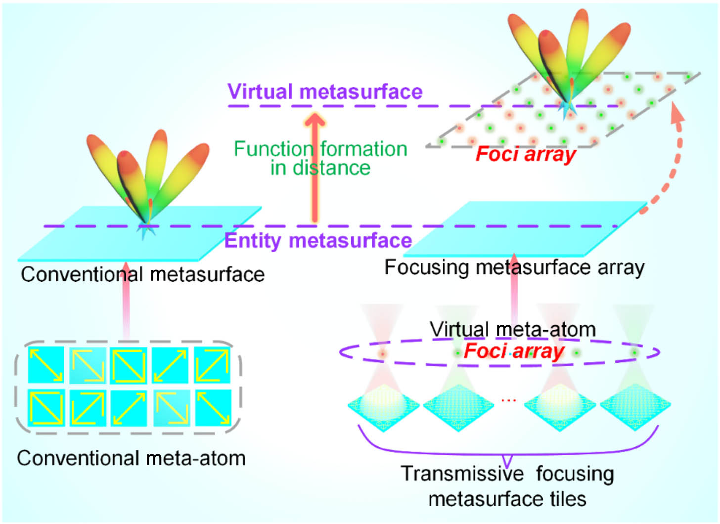
Fig. 1. Schematic diagram of the virtual metasurface compared with the conventional one.
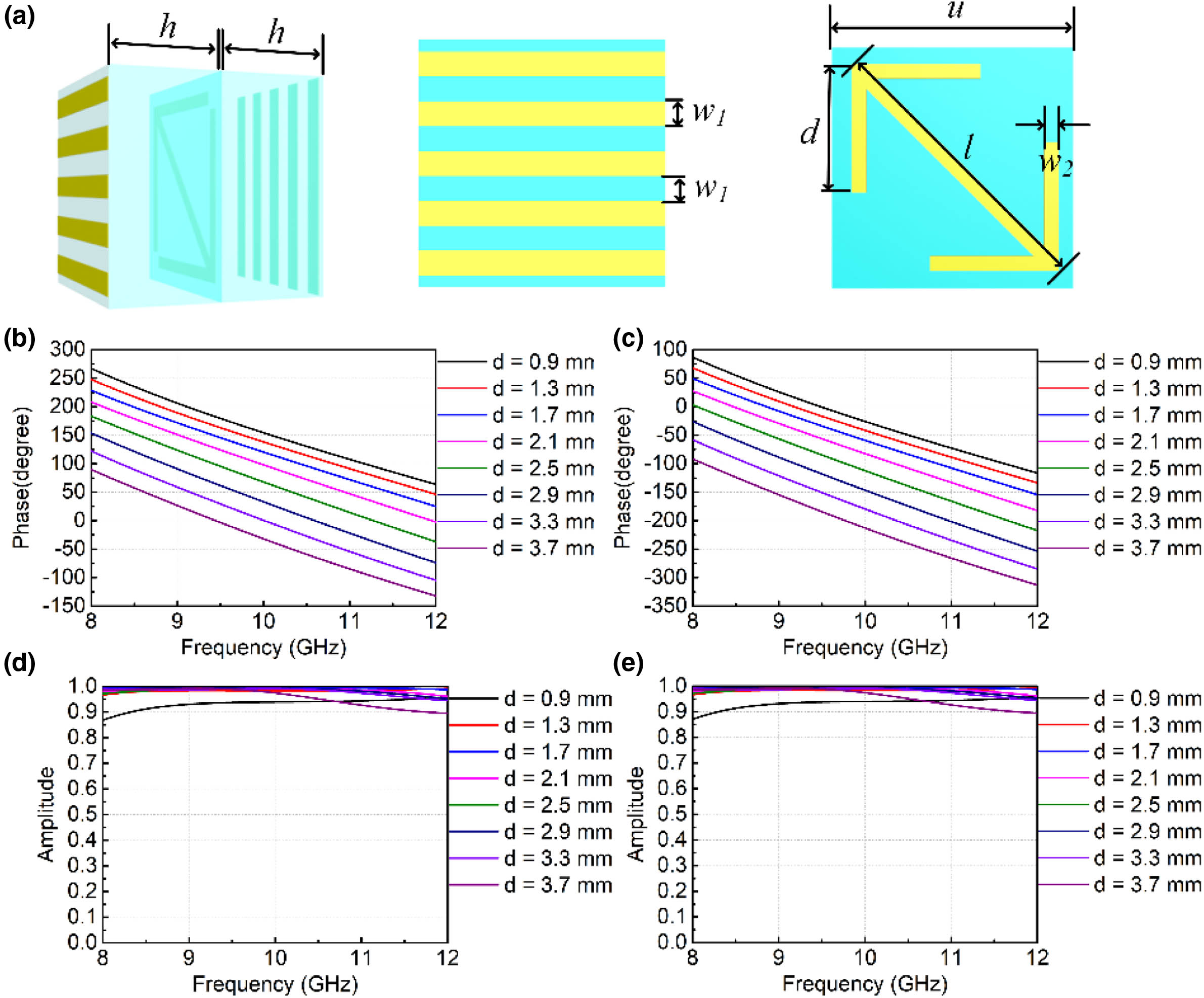
Fig. 2. Structure and network design: (a) geometrical parameter of unit in front view and side view; (b) phase response when the length changes from 0.9 to 3.7 mm, and the step length is 0.4 mm; (c) phase response after rotating the unit 90 deg; (d) amplitude of cross-polarized wave when the length changes from 0.9 to 3.7 mm, and the step length is 0.4 mm; (e) amplitude response after rotating the unit 90 deg.
Fig. 3. Design of focusing metasurfaces and generation of virtual meta-atoms: (a), (b) two phase profiles of metasurface with a 180 deg phase difference; (c), (d) generated focusing metasurfaces filled according to the phase profiles in (a) and (b); (e), (h) distributions of electric fields E x XOZ plane; (f), (i) electric field intensity distribution on the XOY plane when Z = 30 mm XOY plane when Z = 30 mm
Fig. 4. Virtual metasurface design and verification: (a) focusing metasurfaces are spliced together according to the chessboard arrangement; (b) the intensity distribution of E x E x
Fig. 5. Verification that the far-field scattering modulation is realized by the VM rather than the entity metasurface: (a) virtual metasurface is aligned with the obstacle (a metal plate with spaced apertures); (b) the phase profile of entity metasurface; (c) the intensity distribution of E x E x
Fig. 6. Sample fabrication and performance verification: (a) the photographs of TFMTs; (b) the photographs of spliced TFMTs according to checkerboard configuration and the samples with obstacle; (c) near-field measurement environment; (d) far-field measurement environment; (e), (f) the electric field distributions in XOZ cross sections of the 0 and 1 focusing metasurfaces; (g) the electric field distributions in XOY cross sections of the virtual metasurface with checkerboard configuration; (h) the measured far-field radiation patterns under the chessboard arrangement when φ = 45 ° φ = − 45 ° φ = 45 ° φ = − 45 °
Fig. 7. Fitting performance of neural network.
Fig. 8. Theoretical formation path of focus and more aperture sizes: (a) theoretical formation path of focus; (b) 3D far-field result with obstacle when H R = 20 mm R hole = 19 mm H R = 25 mm R hole = 16 mm H R = 30 mm R hole = 13 mm
Fig. 9. Cross profile comparison between the existence of obstacles and the absence of obstacles: (a) comparison of entity metasurface; (b) comparison of VM.


Set citation alerts for the article
Please enter your email address

© Copyright 2018-2021 | Chinese Laser Press. All Rights Reserved 沪ICP备15018463号-20