Metasurface has provided unprecedented freedoms in manipulating electromagnetic (EM) waves, exhibiting fascinating functions. Conventionally, these functions are implemented right on metasurfaces, where spatial modulations on EM wave amplitudes or phases are achieved by meta-atoms. This study proposes the concept of virtual metasurface (VM), which is formed by arrays of foci away from the entity metasurface. Unlike conventional metasurfaces, spatial modulations on the amplitudes or phases of EM waves occur in the air, with a focal length distance from the entity metasurface. As a proof of concept, we demonstrated a transmissive VM. The entity metasurface consists of transmissive focusing metasurface tiles (TFMTs) with the same focal length. Two TFMTs were designed with phase difference to enable the most typical checkerboard configuration. The TFMTs were assembled to form the entity metasurface, whereas their foci formed the VM. Due to the phase difference among adjacent foci, EM propagation along the normal direction was cancelled, leading to four tilted far-field beams. The concept of VM can be readily extended to higher frequencies from terahertz to optical regimes and may find wide applications in communication, camouflage, and other fields.
1. INTRODUCTION
Metamaterials are artificial composite structures composed of periodic or quasi-periodic sub-wavelength structural units, which realize a series of functions with exotic electromagnetic (EM) characteristics through specific arrangement and combination. By introducing EM resonance, metamaterials can customize the dielectric constant and permeability, and then complete the modulation of EM wave characteristics [1–3]. The equivalent EM parameters of metamaterials can be customized, thus causing many novel physical phenomena, such as negative refractive index material [4], perfect absorber [5], flat lens [6,7], and invisibility cloak [8,9]. With these characteristics, metamaterials have contributed greatly to microwave, optics, stealth, and other fields.
As the two-dimensional counterpart of metamaterials, metasurface perfectly inherits the characteristics of metamaterials and realizes further the flexible control of EM characteristics in the plane. Metasurface constructed by identical or distinct planar units overcomes effectively the heavy weight and huge bulk of traditional metamaterials [10]. Furthermore, by customizing the order of cell arrangement, metasurfaces exhibit some fascinating wave-manipulation effects such as phase, amplitude, polarization, and propagation mode [11–14]. In general, tailoring the spatial inhomogeneity of metasurfaces to exhibit certain predetermined phase distributions can reshape the wavefronts of EM wave based on the Huygens–Fresnel principle [15]. Especially, metasurfaces could achieve manipulation of the wavefront of the light through careful design of meta-atoms, which will inspire device miniaturization and functional integration design [16]. The introduction of generalized Snell’s law pioneered the phase-modulated metasurface [11], which exhibits great freedom in EM wave modulation and creates plenty of outstanding contributions in anomalous reflection of light field [17–20]. Some phase modulation mechanisms, such as Huygens’ metasurfaces, multi-resonance, and Pancharatnam–Berry phase and detour phase, are widely used in functional metasurface design, thus playing an important role in the reconstruction of light profiles. Typically, the functions of meta-lens [21,22], meta-holograms [23–26], and optical vortexes [27–29] can be achieved by phase modulation. The propagation of wavefronts can be customized by tailoring phase compensation and phase profile. In focusing design, the meta-atoms with different phase responses are compensated at different positions of the metasurface aperture to focus the wave energy [30,31]. In vortexes design, vortex beams can be generated by tailoring two-dimensional resonator array with the spiral phase profiles to effectively expand the communication capacity [32,33]. More complex designs, such as phase-only holograms, optimize the distribution of EM fields in space to display the desired information [34,35]. The phase-only metasurface holography optimizes the phase profile by iterative or point source algorithm to display the specified image [36]. The Gerchberg–Saxton (GS) algorithm [37,38], and iterative Fourier or Fresnel transform algorithms (IFTA) [39,40] are commonly used to optimize the phase-only metasurface hologram. In 2014, the concept of coding metamaterials was proposed, which creatively realizes the transformation from analog to digital metasurface [41]. Meanwhile, coding metasurface provides a new way to simplify the metasurface design [42].
Tremendous accomplishments have been achieved in the aforementioned conceptions and works, which laid a substantial foundation for metasurface design. Nevertheless, the existing phase modulation metasurfaces are all materialized structures, that is, the modulation of EM response is realized by designing structure of meta-atoms. By optimizing the structure and arrangement of metasurface, the attributes of incident EM waves can be customized. At the microscopic level, the modulation of EM waves by the metasurface is realized by the composition of the source of wavelets with different properties. Therefore, the meta-atoms can be replaced if the source of wavelet with EM response equivalent to that of the meta-atoms can be designed in the designated space. Alternatively, metasurface can achieve the EM-focusing function by tailoring phase profile [43–47]. In addition, the focus, as the position with the strongest energy, can be regarded as a source of wavelets, and it continues to radiate the EM waves outward. The Huygens–Fresnel principle states that every point on a wavefront is a source of wavelets. These wavelets spread out in the forward direction, at the same speed as the source wave. The new wavefront is a line tangent to all of the wavelets. Remarkably, the EM properties of the focus can be customized by tailoring the metasurface phase profile. Accordingly, taking the focus as a new source of wavelets instead of the traditional meta-atom structure will hopefully realize the incorporeal functional metasurface.
Sign up for Photonics Research TOC. Get the latest issue of Photonics Research delivered right to you!Sign up now
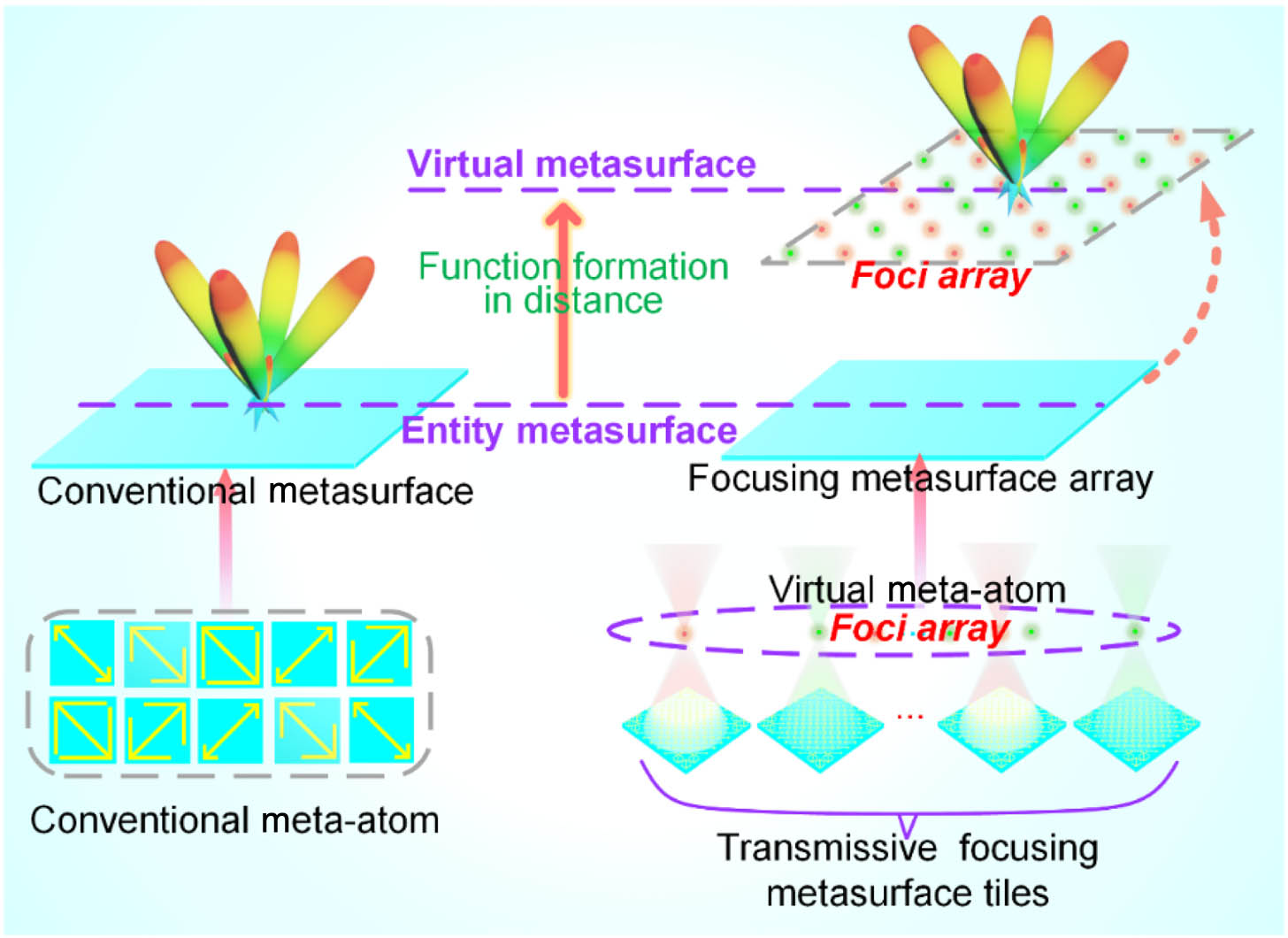
Here, we propose the concept of virtual metasurface (VM). The diagram of our work is presented in Fig. 1. Different from conventional metasurfaces, our designed VM is formed by arrays of foci distant from the entity metasurface. These foci are regarded as virtual meta-atoms, and the manipulation of EM waves can be achieved by tailoring their amplitudes or phases. As a proof of concept, we demonstrate the VMs with the most typical checkerboard configurations. The VMs are formed by arrays of foci, which can be generated from focusing metasurfaces. Therefore, the VMs can be generated from the entity metasurfaces, which consist of a number of transmissive focusing metasurface tiles (TFMTs) of the same focal length. The foci with specified attributes can be tailored by designing TFMTs. The cross-polarized structures with full-phase coverage are adopted to fill the phase profiles. Furthermore, the neural network fitting is applied to assist in the TFMTs design. Based on these, two types of TFMTs with phase difference are designed to generate the foci with phase difference , thus further enabling the checkerboard configuration of VMs. The foci, as new virtual meta-atoms, are assembled to VMs according to the checkerboard configuration. Then, the coding VMs are customized to attain four tilted far-field beams. Additionally, the VM consists of some foci generated by TFMTs, thereby causing the active surface of EM waves to be far away from the entity metasurface with a focal length distance. To verify the concept and capability of VMs, the prototypes of VM were fabricated and measured. The measured results are consistent with the simulated ones, which verifies the VM’s ability of distant manipulation of EM waves. Moreover, the VMs contains entity and virtual parts, which may achieve multiplexing in telecommunications. The spatial modulations on the amplitudes or phases of EM waves actually occur in the air rather than entity, which can cross some obstacles and increase the robustness when transmitting information. In summary, the conception of VM provides a new paradigm for EM regulation, which can be readily extended to designing a great variety of functional devices ranging from microwave to optical regimes.
Figure 1.Schematic diagram of the virtual metasurface compared with the conventional one.
Figure 2 illustrates the structure design with EM response. Figure 2(a) shows the structural parameters of double-head arrow unit of metasurface with orthogonal gratings, which can achieve cross-polarized phase modulation by adjusting the length of arrow. The double-head arrow and gratings are printed in the F4B substrate with a dielectric constant and a loss tangent . The substrate thickness is . The material of pattern and orthogonal gratings is copper with a thickness of 0.017 mm. The periodicity of double-head arrow unit is . The width of gratings is with adjacent metal strips 0.5 mm apart. Furthermore, the geometric parameters of the double-head arrow are as follows. The length of double-head arrow is 6.0 mm, and the width of metal bar is 0.3 mm. The length of the ‘V’ shape is , which will affect the cross-polarized phase response when the length is changed. The double-head arrow structure is a multi-order resonator, which supports multiple plasmon resonances, producing broadband resonance effect. After optimizing the parameters of the structure, the multi-order resonant coupling mode can achieve full-phase coverage. Moreover, full-phase coverage is achieved by adjusting the length of the arrow in this case. The variations between the length and phase are shown in Fig. 2(b), in which the cross-polarized phase can cover 180 deg. Rotate the unit structure 90 deg clockwise, and continue to change the arrow length. The variations of length and phase are shown in Fig. 2(c), from which the cross-polarized phase also can cover 180 deg. The variations between the length and cross-polarized amplitude are shown in Fig. 2(d), in which all the cross-polarized amplitudes are close to 1 at 10 GHz. Figure 2(e) illustrates the amplitude response when the unit is rotated 90 deg, in which all the amplitudes are also close to 1 at 10 GHz. Therefore, the double-head arrow structure can achieve 360 deg full-phase coverage while maintaining transmission efficiency. The relationship between the arrow length and phase presents a mapping form. Machine learning exhibits outstanding performance in exploring the internal relationship of data. A neural network fitting is applied to establish the mapping between the structure and phase response. By introducing a neural network, the interpolation with specified phase can be realized, thus effectively expanding the accuracy of a filling phase profile. The neural network fitting performance is presented in Appendix A. Combining the above analysis, full-phase coverage can be achieved by adjusting the length and rotation angle of the arrow. Furthermore, the phase profiles can be fast customized to generate the specified focus.
Figure 2.Structure and network design: (a) geometrical parameter of unit in front view and side view; (b) phase response when the length changes from 0.9 to 3.7 mm, and the step length is 0.4 mm; (c) phase response after rotating the unit 90 deg; (d) amplitude of cross-polarized wave when the length changes from 0.9 to 3.7 mm, and the step length is 0.4 mm; (e) amplitude response after rotating the unit 90 deg.
Benefiting from the meta-atom phase modulation, the focusing metasurface can be filled according to the phase profile. Due to the different propagation paths of travelling waves in free space, the phase profile is different at each point of metasurface aperture [46,47]. The phase profile of metasurface can be governed by Eq. (1): where is the intial phase at center, and is the wavelength equal to . is light velocity, and is working frequency. is the focal length generated by aperture.
Here, we design two focusing metasurfaces as TFMTs whose focal length is 30 mm working at 10 GHz. The intial phase is 0 and 180 deg, respectively. The theoretical focal length we designed is 30 mm. The phase profiles with different intial phase are shown in Figs. 3(a) and 3(b). The focusing metasurfaces supported by trained neural network filling according to the phase profiles are shown in Figs. 3(c) and 3(d). The two focusing metasurfaces are simulated to observe the focusing performance. The full-wave simulation software is the CST microwave studio. The metasurfaces are placed on the XOY plane, and the boundary is set to open space in all directions. An E-field monitor is set at 10 GHz to observe the electric field distribution. Time domain solver is applied to simulation. The simulation results are shown in Figs. 3(e)–3(j). Figures 3(e) and 3(h) illustrate the distributions of electric fields on the XOZ plane, in which the strongest electric field intensity is located in the center, that is, the focal length is 30 mm. Furthermore, the XOY plane with is extracted to observe the characteristics of focus. The intensity and phase distributions are recorded in Figs. 3(f), 3(i) and 3(g), 3(j), respectively. Figures 3(f) and 3(i) show that the foci are located in the center of the XOY plane, and the intensity values are opposite to each other, which illustrate that the phase difference between them is 180 deg. The phase distributions in the XOY plane are shown in Figs. 3(g) and 3(j), which also illustrate that the phase difference between the two foci is 180 deg. Herein, the foci with different phase responses are reconstructed, that is, the virtual coding meta-atoms are achieved.
Figure 3.Design of focusing metasurfaces and generation of virtual meta-atoms: (a), (b) two phase profiles of metasurface with a 180 deg phase difference; (c), (d) generated focusing metasurfaces filled according to the phase profiles in (a) and (b); (e), (h) distributions of electric fields on the XOZ plane; (f), (i) electric field intensity distribution on the XOY plane when ; (g), (j) phase distribution on the XOY plane when .
The reconstructed foci with a 180 deg phase difference are defined as virtual coding meta-atoms. The VM can be tailored at a distance of focal length. The virtual meta-atom reconstructed foci are arranged in a chessboard periodic arrangement for verifying the VM concept. The arrangement of TFMTs is shown in Fig. 4(a), in which the focusing metasurfaces are spliced together, and the foci form a new virtual metasurface. The spliced TFMTs are placed at the XOY plane, and the -polarized EM wave is perpendicularly impinged on the metasurfaces from the direction. The far-field monitors and electric-field monitors are set at 10 GHz to monitor the far-field beam distribution and the electric field distribution. First, the electric field distributions and phase distributions on the XOY plane () where the foci located are observed in Figs. 4(b) and 4(c), respectively. In Fig. 4(b), the positions with the most powerful electric field intensity are evenly distributed on the plane, and the focal amplitudes of different phases are opposite to each other. Figure 4(c) shows the simulated phase distribution, which also illustrates that the designed virtual meta-atoms have a phase difference of 180 deg. The far-field results are shown in Fig. 4(d), in which four tilted far-field beams are achieved. To prove that the far-field scattering modulation is realized by the VM rather than the entity metasurface, we introduce a metal plate with the hole array to isolate the entity surface from the virtual surface. The more cases of holed obstacles are supplemented in Appendix B.
Figure 4.Virtual metasurface design and verification: (a) focusing metasurfaces are spliced together according to the chessboard arrangement; (b) the intensity distribution of on the focusing plane in chessboard arrangement; (c) the phase distribution of on the focusing plane in chessboard arrangement; (d) the 3D far-field scattering beam of metasurface in chessboard arrangement.
To verify the ability of VM, a metal plate with spaced apertures 25 mm was placed above the metasurface, as shown in Fig. 5(a). Similarly, the electric field distributions and far-field beam distributions are also recorded in Figs. 5(c)–5(g). Figures 5(c) and 5(d) show the intensity and phase distributions of electric field, where the foci are arranged crosswise and the adjacent foci are different. In Fig. 5(e), the VM scattered the EM waves to four tilted far-field beams, which obviously proves that the VM has crossed through the metal plate. Moreover, the efficiency of virtual meta-atom with and without obstacle is also evaluated. The efficiency can be calculated according to the energy of focusing and the energy of incident plane [47,48]. Following calculation, the efficiency of virtual meta-atom without obstacle is 73.86%, and the efficiency of virtual meta-atom with obstacle is 59.61%. The obstacle causes 14.25% energy loss. However, although the obstacle causes energy loss, it has little influence on the final scattering effect, which fully demonstrates the VM robustness.
Figure 5.Verification that the far-field scattering modulation is realized by the VM rather than the entity metasurface: (a) virtual metasurface is aligned with the obstacle (a metal plate with spaced apertures); (b) the phase profile of entity metasurface; (c) the intensity distribution of on the focusing plane in chessboard arrangement with the obstacle; (d) the phase distribution of on the focusing plane in chessboard arrangement with the obstacle; (e) the 3D far-field scattering beam of metasurface in chessboard arrangement with the obstacle; (f) the 3D far-field scattering beam of entity metasurface; (g) the 3D far-field scattering beam of entity metasurface with obstacle.
In addition, we also simulated the entity metasurface as the control group to verify our view. Figure 5(b) illustrates the phase profile of an entity metasurface. The entity metasurface is also placed at the XOY plane, and the -polarized EM wave is perpendicularly impinged on the metasurfaces from the direction. Figure 5(f) shows the far-field of entity metasurface, and Fig. 5(g) illustrates the case with obstacles. Comparing the results of Figs. 5(e) and 5(g), it is obvious that the traditional entity metasurface cannot cross this obstacle, which demonstrate the far-field scattering modulation is realized by the VM rather than the entity metasurface. To further quantify the advantage of VM, the comparison of cross profiles of far-field patterns is supplemented in Appendix C.
3. EXPERIMENT AND VERIFICATION
To further verify our design, the prototypes of TFMTs are fabricated and assembled by commercial printed circuit board (PCB) technology. The photographs of the TFMTs prototypes are shown in Fig. 6(a), which can generate the foci with a 180 deg phase difference. The outer layers are orthogonal metal gratings; therefore, only the pattern of the middle layer is shown in Fig. 6(a). The size of 0 and 1 focusing metasurfaces is , and the foci are regarded as virtual meta-atoms to assemble the virtual metasurfaces. To achieve the reconfiguration of the functional VMs, a number of 0 and 1 TFMTs are processed. The properties of EM waves can be manipulated by arranging and splicing these elements. Because the designed TFMTs need to be spliced according to different arrangements, an extra PMI foam carrier is designed to splice the units. The foam size is , and a slot of is cut out in the middle to splice the metasurface. The foam has a dielectric constant of 1, almost no loss, which is similar to air; therefore, it has little influence on the EM performance of the samples. The spliced TFMTs are embedded in the slot of foam according to the chessboard arrangement, as shown in Fig. 6(b). The spliced TFMTs with obstacle are also shown in Fig. 6(b). Furthermore, the performance of the designed VMs is verified by near- and far-field measurement. Figure 6(c) shows the near-field measurement system carried out in a microwave anechoic chamber with a vector network analyzer (Agilent E8363B), in which the -polarized antenna is set as a transmitter, and the -polarized probe is set above the samples as the receiver to monitor the electric field distribution in space. The electric field distributions of metasurfaces are shown in Figs. 6(e)–6(g). First, the cross sections of the 0 and 1 focusing metasurfaces are measured, where the strongest field intensity is located at 30 mm, that is, the foci are at 30 mm. In addition, the electric field intensity of the two foci is opposite, indicating the phase difference of the two foci is 180 deg. Furthermore, the electric field distributions of XOY cross sections located 30 mm above the spliced metasurface are monitored and recorded in Fig. 6(g), in which the distributions of foci are consistent with the checkerboard configuration. Some noise points at the edge of the electric field distributions, which are caused by edge scattering and measurement error. However, the center of the cross section can clearly observe the orderly arrangement of the foci. Near-field measurement effectively verifies that a new metasurface, namely VM, is constructed above the TFMTs through the arrangement of foci. To further observe the modulation of EM wave by the VMs, far-field measurements are carried out in the microwave anechoic chamber, which is shown in Fig. 6(d). The samples are placed on the turntable mount to measure the scattering directivity diagram. A pair of X-band horn antennas are employed for measurement, one of which is used as a transmitter and the other as a receiver. The measured far-field scattering patterns are recorded in Fig. 6(h), in which the experimental results are in good agreement with the simulation results. The measured results show that the checkerboard VM scatters the incident wave into four beams. As shown in Fig. 6(i), we also measured the far-field scattering patterns of metasurface with obstacle, which scatters incident wave into four beams. The measured results demonstrate that the far-field scattering modulation is realized by the VM rather than the entity metasurface. All the experimental results demonstrate the performance of the samples and the effectiveness of the design method. Furthermore, the performance of samples illustrates the feasibility of the VM concept.
Figure 6.Sample fabrication and performance verification: (a) the photographs of TFMTs; (b) the photographs of spliced TFMTs according to checkerboard configuration and the samples with obstacle; (c) near-field measurement environment; (d) far-field measurement environment; (e), (f) the electric field distributions in XOZ cross sections of the 0 and 1 focusing metasurfaces; (g) the electric field distributions in XOY cross sections of the virtual metasurface with checkerboard configuration; (h) the measured far-field radiation patterns under the chessboard arrangement when and on orthogonal diagonal lines; (i) the measured far-field radiation patterns under the chessboard arrangement with obstacle when and on orthogonal diagonal lines.
This study proposed the conception of VM, which is formed by arrays of foci distant from the entity metasurface. These foci, as the source of wavelets, can be considered as virtual meta-atoms, and the manipulation of EM waves can be achieved by tailoring their amplitudes or phases. Different from the conventional entity metasurfaces, spatial modulations of EM waves actually occur in the air with a focal length distance from the entity metasurface. The VM effectively transforms the active surface of EM waves and provides a new approach for EM modulation. Two TFMTs with phase difference were customized to enable a checkerboard configuration. The TFMTs were assembled to form the entity metasurface whereas their foci formed the VM. Foci, as new virtual meta-atoms, were spliced into VMs according to the checkerboard configuration, and the four tilted far-field beams were obtained. The performance of scattering beam control of VMs was simulated and measured. The measured results are consistent with simulated results, which verifies our design. Moreover, the VM can also be extended in the modulation of reflected waves and so on. Virtualization is a novel paradigm of reconstructing the metasurface design, which can effectively design the substitute of entity metasurface through equivalent meta-atoms performance. Most importantly, the conception of VM can be used as a novel paradigm to support material design.
APPENDIX A: NEURAL NETWORK FITTING
Here, the neural network fitting was employed to establish the mapping between the phase and structure. The length of ‘V’ shape affects the phase response. When the length varies from 0.9 to 3.7 mm, the phase can cover 180 deg. When the length varies from 0.9 to 3.7 mm after a 90 deg rotation, the phase can cover the remaining 180 deg. To simplify the design, we set the cell length from the range 0.9–3.7 to the range 3.7–6.4 when the cell is rotated 90 deg. The fitting performance is presented in Fig. 7, in which the blue points are training, green points are validation, and red points are test data. The pink curve is a fitting curve. The fitting degree of fitting curve is .
The aperture size of the holed obstacle will affect the focusing performance. Therefore, we calculated the theoretical aperture size of the foci array. The theoretical no-impact aperture size of the holed obstacle can be obtained by calculating the formation path of the focus. The formation path of the focus is illustrated in Fig. 8(a). When the aperture is larger than the theoretical formation path, the synthesis effect is not affected. As shown in Fig. 8(a), the radius of the focus is , the radius of obstacle’s hole is , the height of obstacle is , the focal length is , and the radius of metasurface aperture is . The minimum radius of obstacle’s hole can be calculated by
Figure 8.Theoretical formation path of focus and more aperture sizes: (a) theoretical formation path of focus; (b) 3D far-field result with obstacle when and ; (c) 3D far-field result with obstacle when and ; (d) 3D far-field result with obstacle when and .
According to Eq. (B1), the minimum radius of obstacle’s hole can be calculated, and the specified holed obstacles can be established. Here, three additional obstacles with holes were placed to further examine our design. When , 25, and 30 mm, the theoretical aperture sizes are , 16, and 13 mm, respectively. The far-field scattering patterns for these three cases are simulated, which are shown in Figs. 8(b)–8(d). All the far-field results show four tilted far-field beams similar to the VM without obstacles, which fully demonstrate our design.
APPENDIX C: COMPARISON OF CROSS PROFILE OF FAR-FIELD
To further quantify the performance of the VM, the cross profiles of far-filed results at are plotted in Fig. 9. Figure 9(a) shows the far-field patterns of the entity metasurface and the entity metasurface with obstacle. Figure 9(b) shows the far-field patterns of the VM and the VM with obstacle. From the comparison of far-field patterns between the entity metasurface and VM, the robustness of VM can be verified. The VM has no obvious difference when there are obstacles. However, the entity metasurface shows a difference. Therefore, the obstacle-avoidance can be verified.
Figure 9.Cross profile comparison between the existence of obstacles and the absence of obstacles: (a) comparison of entity metasurface; (b) comparison of VM.