
Xu-Zhen Gao, Yue Pan, Guan-Lin Zhang, Meng-Dan Zhao, Zhi-Cheng Ren, Chen-Ghou Tu, Yong-Nan Li, Hui-Tian Wang. Redistributing the energy flow of tightly focused ellipticity-variant vector optical fields[J]. Photonics Research, 2017, 5(6): 640
- Photonics Research
- Vol. 5, Issue 6, 640 (2017)
![(a) Schematic of the PS in the spherical coordinate system represented by the traditional latitude and longitude circles, (b) the sine-form varying ellipticity ϵA in a range of [−1,1] along δ, and (c) the sine-form varying ellipticity ϵB in a range of [0, 1] along δ.](/richHtml/prj/2017/5/6/06000640/img_001.jpg)
Fig. 1. (a) Schematic of the PS in the spherical coordinate system represented by the traditional latitude and longitude circles, (b) the sine-form varying ellipticity ϵ A [ − 1 , 1 ] δ ϵ B δ
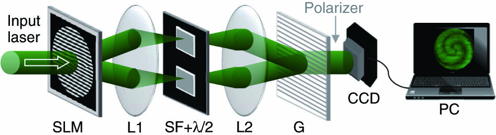
Fig. 2. Schematic of the experimental setup for generating the desired EV-VOFs. L1 and L2, a pair of lenses; λ / 2
Fig. 3. Generated EV-VOFs when ( m , n ) = ( 1 , 0 ) x [ − 1 , 1 ]
Fig. 4. Generated EV-VOFs when ( m , n ) = ( 1 , 0 ) x
Fig. 5. Intensity distributions and the Poynting vectors in the focal plane of the tightly focused EV-VOFs with the sine-form varying ellipticity in a range of [ − 1 , 1 ] ( m , n ) = ( 2 , 0 ) 4 λ × 4 λ
Fig. 6. Schematic structures of the phase masks and the Poynting vectors of the tightly focused EV-VOFs with the sine-form varying ellipticity in a range of [0, 1] when ( m , n ) = ( 1 , 0 ) 4 λ × 4 λ
Fig. 7. Transverse components of the Poynting vectors of the tightly focused EV-VOFs with the sine-form varying ellipticity in a range of [0, 1] when ( m , n ) = ( 1 , 0 ) π / 4 π / 2 3 π / 4 4 λ × 4 λ
Fig. 8. Intensity distributions and the Poynting vectors of the tightly focused vortex EV-VOFs with the sine-form varying ellipticity in a range of [0, 1] when ( m , l ) = ( 3,1 ) 4 λ × 4 λ
Fig. 9. Transverse components of the normalized Poynting vectors of the tightly focused vortex EV-VOFs with the sine-form varying ellipticity in a range of [ − 1 , 1 ] ( m , l ) = ( 1 , 5 ) , ( 2 , 5 ) , ( 3 , 5 ) , ( 4 , 5 ) , ( 5 , 5 ) 4 λ × 4 λ

Set citation alerts for the article
Please enter your email address
© Copyright 2018-2021 | Chinese Laser Press. All Rights Reserved 沪ICP备15018463号-20