
Dewen Cheng, Jiaxi Duan, Hailong Chen, He Wang, Danyang Li, Qiwei Wang, Qichao Hou, Tong Yang, Weihong Hou, Donghua Wang, Xiaoyu Chi, Bin Jiang, Yongtian Wang, "Freeform OST-HMD system with large exit pupil diameter and vision correction capability," Photonics Res. 10, 21 (2022)
- Photonics Research
- Vol. 10, Issue 1, 21 (2022)
Abstract
1. INTRODUCTION
An optical see-through head-mounted display (OST-HMD) can optically superimpose computer-generated virtual scenes onto the views of a real-world scene in mixed or augmented reality systems [1]. Rather than a video see-through approach, the OST-HMD has an actual direct view of the space in front of the user, which introduces minimal degradation to real-world scenes. The OST-HMDs are widely employed in the fields of medicine [2], manufacturing [3], scientific visualization [4], aviation [5], education, and entertainment [6].
However, it is difficult to achieve a large field of view (FOV), low F/#, compact, and nonintrusive OST-HMD through a nonpupil-forming system [1]. Optical designers have tried various optical solutions for such problems, including, but not limited to, catadioptric systems, geometric waveguides, diffraction waveguides, freeform prisms, light fields, and metasurfaces. Each of these technologies has a unique disadvantage. For example, although a catadioptric lens system can avoid the effects of stray light and ghost images, achieving a compact form may deem quite challenging [7]. Similarly, the optical distortion of the projected image is difficult to correct during the design process [8–10]. The OST-HMD integrating the projection optics and waveguide easily meets the requirements of small thickness and light weight. However, the stray light of the geometrical waveguide severely degrades the display quality when high processing technology is required [11–14]. For diffraction waveguides, it is still difficult to develop full-color, high-resolution displays that are free of artifacts such as speckles [15–20]. Improvements in design and manufacturing ability have made freeform optics broadly applied to imaging systems [21–25]. The performance of the freeform prism OST-HMD has progressed significantly. Thus, a wide FOV and low F/# OST-HMD can be achieved using a freeform prism while maintaining compactness and light weight, but large distortion and anamorphic ratio remain [26–28]. A light-field near-eye display can obtain a corrected depth perception of the virtual information in OST-HMD applications. Transparent display panels are rare and have low resolution, which cannot be achieved in a short time [29,30]. Metasurfaces have shown remarkable potential for manipulating light in imaging systems [31–36]. Metalens, produced only by nanoimprinting, can overcome the existing bottleneck imposed by the narrow FOV and bulkiness of the current systems. The limitation of processing methods is their inability to be widely promoted [37].
OST-HMD system structures are classified into four types: general catadioptric system, diffractive waveguide, geometrical waveguide, and freeform prism. Table 1 lists the module views, pros, and cons of these four solutions as well as commercially available HMD products based on these solutions, such as ODG R-9 [38], Magic Leap 1 [39], Lumus DK-52 [40], and our previous design in Ref. [26].
Comparison of Four OST-HMD Optical Solutions
Sign up for Photonics Research TOC. Get the latest issue of Photonics Research delivered right to you!Sign up now
The development of freeform surface description and design methods has promoted a revolutionary leap for the advancement of the OST-HMD technology. Although the freeform element is thicker than waveguides, plastic material has much less specific gravity and keeps its weight. Its fundamental difference from waveguides is that light efficiency of freeform prisms is no longer restricted by diffraction efficiency or reflectance of reflective mirrors, so its light efficiency is higher than those of waveguides and general catadioptric systems. That is why the waveguide OST-HMD system needs a Pico projection system, and the overall thickness of the waveguide system is similar to or even larger than that of the freeform optics solution. Briefly, the freeform prism is an advantageous modern solution to achieve OST-HMD designs with better display performance.
In this paper, we present the design of an OST-HMD system that includes three wedge-shaped freeform prisms and two lenses. Using a 0.71-in. (1 in. = 2.54 cm) microdisplay, the system offers a diagonal FOV of 45.3°, an F/# of 1.8, an eye relief of 18 mm, an exit pupil diameter as large as
2. PREVIOUS RESEARCH
The concept and development of freeform prisms have been elaborated in previous studies [26]. Freeform prisms have shown significant advantages in the design of compact HMD systems. The wedge-shaped freeform prism provides full play to the characteristics of the total internal reflection and minimizes light loss. The correcting plate effectively corrects the see-through light path, reduces deformation of the external scene, and achieves high-quality virtual and real registration. After extensive research, the freeform prism has been applied to current OST-HMD systems and has been commercially available. Many companies, such as Olympus [41], eMagin [42], and Rockwell Collins [43], have released HMDs or optical modules based on freeform prisms.
In our previous research paper [26], we designed an OST-HMD based on a freeform prism. Along with the deep development of the study, different types of freeform prism OST-HMDs have been commercially available [44]. However, the shortcomings of the design in Ref. [26] still intervene with the wearable experience. For example, if the distortion of the virtual image light path is up to 12%, electronic correction is required when this optical system is applied in OST-HMD applications. Although the see-through distortion is only 1.4%, the design process of the auxiliary prism is complicated and difficult, and the image quality of the real scene decreases. Diopter adjustment is also an important function for OST-HMDs. Previous designs cannot achieve diopter adjustment, causing some users to wear two pairs of glasses.
To address the problem of see-through distortion of freeform prism OST-HMD, an auxiliary lens was added between the main wedge-shape prism and the eye [45]. This auxiliary lens can also achieve the diopter adjustment function [46,47]. In Table 2, we list the optical path evolution process. In this paper, we compare our previous design, the three-piece prism design [45], and our present design across all aspects.
Specifications of Different Freeform Prisms
The current solution entails that the distortion of the virtual image light path is less than 0.6% without electronic correction, projecting a clear and undistorted image from the microdisplay to the user’s eye. In addition, a larger exit pupil diameter is achieved in this new design, thereby simplifying the structure by avoiding the pupil adjustment mechanism. Due to the addition of the auxiliary lens, which makes the optical surface near the human eyes flat or spherical, it is much easier to design the see-through light path in the present design. In addition, we achieve diopter adjustment by changing the shape of the first surface of the auxiliary lens to meet the diopter needs of different users, while other optical elements remain unchanged. This process is described in Section 4.B. Although the FOV of the present design is slightly smaller than that of our previous design, it is similar to other optical solution types and is still able to meet the usage requirements of AR applications.
3. DISPLAY PRINCIPLE AND SYSTEM SPECIFICATIONS
An optical see-through HMD typically consists of an optical path for viewing a displayed virtual image and a path for viewing a real-world scene directly. The previous design included only two freeform elements: a main prism and a correct plate. Although it had a larger FOV, lighter weight, and simpler structure, it retained unsolvable defects, as mentioned in Section 2. Therefore, it is necessary to improve the performance of previous designs. The OST-HMD optical system presented in this study is shown in Fig. 1. The overall system is set to be symmetric about the YOZ plane, comprising three freeform prisms and two rotationally symmetric lenses.
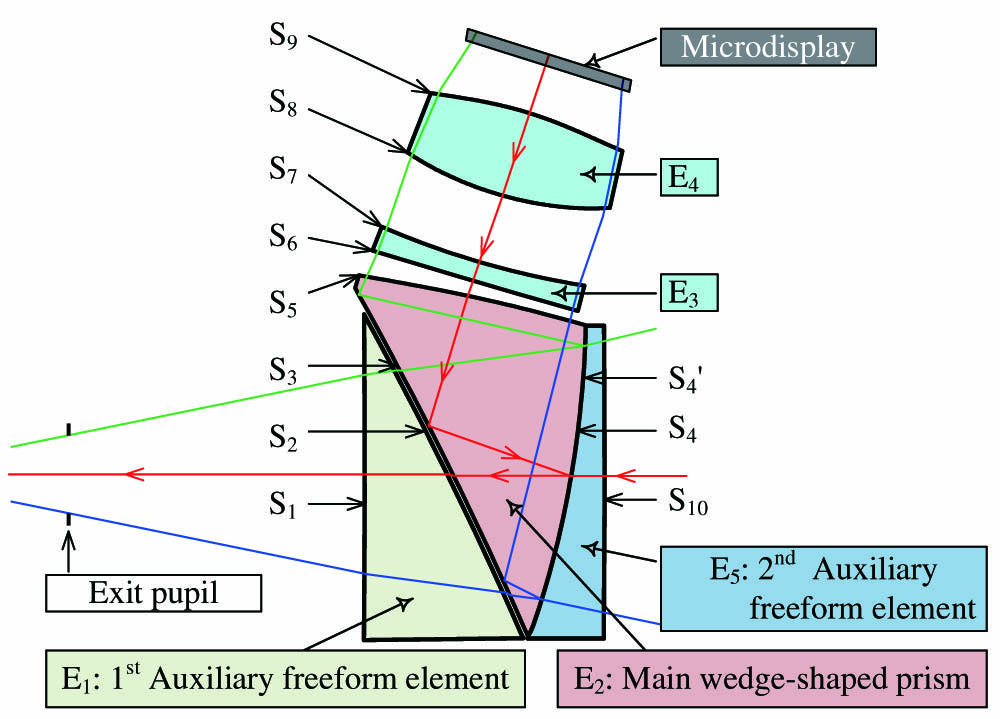
Figure 1.Layout of the final OST-HMD system.
In the present design, two extra lenses close to the microdisplay are used to improve the image quality of the system, balancing the performance across the entire exit pupil. The wedge-shaped freeform main prism
As shown in Fig. 1, the wedge-shaped freeform prism
For the elements in the optical system, the main prism and 1st auxiliary freeform element are adjacently arranged. The surface
The virtual image light path consists of the 1st auxiliary freeform element
Some transmission light is lost during the first reflection on surface
For the see-through light path, light from the real-world scene enters surface
Surface
In the previous design [26], the surface close to the eyes is a freeform surface, causing viewing axis deviation, undesirable distortion, and other off-axis aberrations in the view of the real-world scene. Although the correcting plate corrected the deviation of the optical axis and the off-axis aberrations introduced by the freeform prism, there is still approximately 1.4% distortion of the see-through light path. The design of the correcting plate was complicated. However, in the present design, the surface close to the eyes is flat or spherical, which simplifies the design process of the see-through light path and reduces the distortion. In addition, the 1st auxiliary lens
The overall specifications of the system are listed in Table 3. Based on various considerations of volume, resolution, availability, and cost, a 0.71-in. organic LED (OLED) display with a resolution of
Overall Parameter Requirements of the System
| Parameter | Specification |
|---|---|
| Active display area | |
| Resolution | |
| Effective focal length (EFL) | 21.6 mm |
| Exit pupil diameter (EPD) | |
| Eye relief (ERF) | 18 mm |
| F/# | 1.8 |
| Lens type | Freeform |
| Wavelength | 486.1–656.3 nm |
| Field of view (FOV) | 45.3° (diagonal) |
| Virtual image distortion | |
| See-through distortion | |
| Modulation transfer function (MTF) |
The difference between two kinds of distortion is that virtual image distortion describes the deforming of the image displayed on the screen, resulting from the virtual image optics.
The see-through distortion is about the deformation of the real scene, which cannot be corrected by the image prewarping method.
In a freeform optical system, the distortion can be quite large and irregular if there are no constraints. Therefore, we need to control the imaging distortion to less than 0.6% to avoid electronic correction of the initial image source. Compared with other evaluation methods of image quality, the modulation transfer function (MTF) is more suitable for evaluating the overall image sharpness. The MTF value would be better than 40% at a spatial frequency of 50 lp/mm in the full FOV.
4. DESIGN OF THE VIRTUAL IMAGE LIGHT PATH
The additional use of the 1st auxiliary freeform lens
A. Structure Constraints
To guarantee that the rays of all fields pass through the optical system correctly and enter the user’s eyes, it is essential to control the structure of the main freeform prism, make its three surfaces form a valid prism shape, and ensure that the center and edge thicknesses meet the manufacturing requirements. The methods to optimize the physical structure of the wedge-shaped freeform prism are as follows.
By controlling the position relations of specific points and lines, we can constrain the structure of the main prism. Figure 2 illustrates the structural control method employed in this study. Two reference rays are selected to follow the constraints in the optimization process: the upper marginal ray,
![]()
Figure 2.Optical paths of the rays of different object fields.
By constraining the points
Commercial optical design and analysis software CODE V [48] develops a physical structure control function, referred to as JMRCC, which can be used to define the aforementioned constraints easily. This function computes the signed perpendicular distance from a point to a line in the
![]()
Figure 3.Schematic diagram of JMRCC basic principle, wherein
According to the above discussion, the constraints to maintain the physical structure of the main prism can be given as follows:
Similarly, we can construct specific constraints and use the JMRCC function to effectively ensure the shape of all prisms logically.
B. Diopter Adjustment Based on Changing the 1st Auxiliary Freeform Lens
For most OST-HMD systems, devices did not include diopter adjustment. Users with myopia or hyperopia were required to wear two pairs of glasses simultaneously. Some devices attained diopter adaption by placing an additional corrective lens between the human eye and OST-HMD, as shown in Fig. 4(a), but such deemed tedious for users to fit it [46]. Meanwhile, the corrective lens complicates the system structure to a certain extent. Hence, the volume and weight of the device will increase accordingly. This is not in line with our original intention of lightweight and compact characteristics in our design concept.
![]()
Figure 4.Diopter adjustment diagram of freeform prism OST-HMD. (a) Traditional diopter adjustment scheme, where additional lens was added between human eye and prism. (b) Correct hyperopia through auxiliary prism with convex
The system presented in this paper can address this problem by customizing the 1st auxiliary freeform lens according to the users’ diopters. For users with normal diopters, the optical surfaces,
When the user’s diopter changes, the diopter adjustment function can be achieved by replacing auxiliary lens
5. OPTIMIZATION METHODS
Based on the system specifications and design methods outlined in Sections 3 and 4, the optimization process of the OST-HMD optical system is introduced in detail in this section. The optimization of the virtual image light path, correction of distortion, and balance of the system performance attained by the automatic method in the entire FOV are emphasized.
A. Optimization of the Virtual Image Light Path
The optimization process has been thoroughly analyzed in a previous paper [14], but a brief introduction is provided here. Based on the previously designed system, an auxiliary freeform lens was added to the light path. By preliminary scaling, the parameters of the initial structure gradually approximated the requirements.
Modeling this system in CODE V, the optimization process is always based on the TIR constraints, structural constraints, and the basic optical definitions such as effective focal length, outlined in Section 4. Unlike the rotationally symmetric system, the freeform prism has only single-sided symmetry. Therefore, the setup method of linear field sampling along the radial direction is no longer applicable, and the freeform prism design must be optimized for half of all FOVs sampled in a rectangular grid. An incremental optimization strategy was adopted. With the improvement in system performance during the optimization process, we gradually increased the number of field samples and the degree of freedom of the surface. The surface type of the prism is converted from spheric to aspheric, then anamorphic, and finally XY polynomial. Compared with the design in the previous paper [26], the present main prism has only two freeform surfaces,
B. Distortion Correction
In the imaging optical system, improving the imaging quality is the main task, and the ultimate goal is to obtain an image that is completely similar to the object on the focal plane. However, the actual optical system can only form a perfect image when the object point is paraxial, and a thin beam is observed. The outward expansion of the FOV and aperture destroys the concentricity of the imaging beam and produces various imaging defects; thus, the shape of the image and object cannot be completely similar.
The correction of optical distortion, in a fundamental sense, is to change the relative positional relationship between the image points on the image plane or to rearrange the image points so that the observer or camera can capture an undistorted image. The correction of distortion requires changing the conjugate relationship between the object and image points. A new conjugate relationship between the object and image can be achieved by controlling the positioning of rays reached in the image plane, resulting in a smaller distortion ratio.
Generally, for an optical system with rotational symmetry, only radial distortion should be considered. Figure 5(a) shows a schematic diagram of radial distortion, where
![]()
Figure 5.Schematic diagram of distortion control. (a) For rotational symmetry system, radial distance of
In theory, a freeform surface has a different curvature at each point. Thus, the freeform surface can control the optical path difference, luminous flux, and even the direction and position of the rays according to the image quality requirements more easily. Therefore, the freeform surface can be used to grasp the direction of rays emitted from each FOV and control the position of each image point reached on the image plane.
For an OST-HMD optical system, both the distortion of the virtual image light path and see-through path must be corrected. On the one hand, the freeform system produced large distortion when projecting the image displayed in microdisplay into the human eye. Due to the off-axis property of freeform prisms, the produced distortion is also asymmetry. On the other hand, when users see the external scene through the OST-HMD, the deformation of the real-world scene caused by the see-through distortion critically affects the virtual and real registration of the system.
For the design in our previous paper [26], due to the trapezoidal shape distortion caused by the off-axis property of freeform prisms and the presence of a small amount of lens barrel distortion, the distortion grid in the virtual image light path is as high as 12% in the upper left/right corner, as shown in Fig. 6(a), which is difficult to correct. The distortion of the see-through light path was 1.4%, although a complicated design process was executed, as shown in Fig. 6(b). In addition, to control the asymmetry distortion, the effective focal lengths in the
![]()
Figure 6.Distortion grids of the previous system and present system. (a) Distortion grid of the previous virtual image light path, maximum ratio is 12% [26]. (b) Distortion grid of the previous see-through path, maximum ratio is 1.4%. [26]. (c) Distortion grid of the present virtual image light path, maximum ratio is 0.6% without anamorphosis. (d) Distortion grid of the present see-through path, the maximum ratio is 0.4% without anamorphosis.
However, for the current solution, the optimized distortion of the virtual image light path is now less than 0.6% before electronic correction, while the difference in the distortion rates between the
Further, the MTF of the see-through light path is improved, as shown in Fig. 7. Figure 7(a) shows the MTF plot of the previous design [26], where the value is greater than 0.1 at 50 lp/mm for all sampled fields. The MTF value of the present design is 0.9 at 50 lp/mm for all fields, which implies a better see-through performance.
![]()
Figure 7.See-through MTF plot of the previous and present systems. (a) MTF plot of previous design in Ref. [26], the value is higher than 0.4 for most fields at 50 lp/mm. (b) MTF plot of present design, the value is higher than 0.9 for all fields at 50 lp/mm.
C. Automatic Image Performance Balancing Method
To further improve the optical performance of the system, the system performance of the entire FOV must be balanced, by continuously adjusting the weight of the sampling field and azimuth. In most cases, the default weights provided by the software will be used for optimization, or a more appropriate set of weights will be assigned based on experience. After each optimization trial, the designer needs to adjust the weight of the sampling field and the azimuth according to the optimization results and design requirements and then use the original constraints and new constraints to optimize the system again to seek the best optimization results. This can be a long and tedious process for optical designers.
Our previous work [49] introduced an automatic image-performance balancing method. An outer loop was added for automatic weight adjustment for optimization. First, we set the initial weights for all the sampled fields and azimuths to an equal value and evaluated the image performance before each optimization trial to calculate the weights for the next trial. The sampled fields and azimuths with performance values lower than the average were assigned higher weights and vice versa. When the exit condition is reached, the loop ends.
When designing a freeform optical system, global optimization is also a way to balance image performance. However, in this study, the design included two freeform optical surfaces; over 100 parameters were defined as variables, and 25 fields were sampled. It requires several minutes to complete a single local optimization loop and requires more than 100 h to finish a global optimization loop. However, by employing the automatic balancing method, the balancing process is completed within half an hour. Finally, through several automatic optimization trials to achieve the performance balance of the entire FOV, the overall optical performance of the system can be improved. Figure 8(a) shows the error function variations for different optimization trials of automatic balancing. The value dropped from 71 for the original design to 50 after 10 trials of optimization, and the rapid descent occurred in the first four to seven trials. After completing all optimization steps, the final system is obtained, and the layout is shown in Fig. 8(b).
![]()
Figure 8.(a) Error function variation curve. (b) Final optical layout of the OST-HMD.
The MTF plot of the optical system before and after balancing is shown in Fig. 9. Uniformity of the MTF value for full fields has been greatly improved. Besides, because of the use of a pair of positive and negative lenses, the lateral color aberration is fully corrected.
![]()
Figure 9.MTF plot of the optical system. (a) The MTF plot before automatic balancing, MTF value is higher than 0.18 at 50 lp/mm for all fields. (b) The MTF plot after automatic balancing, MTF value is higher than 0.4 at 50 lp/mm for all fields.
For a visual system, the relative position between human eye and exit pupil of the OST-HMD is always unstable. Eye shift or rotation caused by the difference in face shape between individuals and other factors should be considered. To evaluate the image performance when the eye shifts in the area of the exit pupil, additional MTF plots are given in Fig. 10. A major assumption is that the pupil size of the human eye is 3 mm under normal light conditions. In the area of the exit pupil, three positions including center, 2.5 mm offset to the right from center, 2.5 mm offset upwards from center, are chosen for evaluation. The results show that the MTF values of all fields are higher than 0.4 at 50 lp/mm, indicating the MTF performance at different positions meets the design requirement.
![]()
Figure 10.MTF plots for different eye positions. (a) MTF plot when eye locates in center of eyebox. (b) MTF plot when human eye moves 2.5 mm to the right. (c) MTF plot when human eye moves up 2.5 mm.
D. Tolerance Analysis
Tolerance analysis is an essential part of optical design because it is closely related to optical fabrication, alignment, and cost. By carefully evaluating the parameter-variant/image-effect interaction and paying particular attention to the negative and positive aspects of these interactions, we can avoid overdesign and assign tight tolerances only where needed. Such analysis helps determine the acceptable limits for different fabrication and alignment errors.
Unlike the rotationally symmetric system, the tolerance analysis of the freeform system is more complex, and each surface has many optical parameters that would affect the result. In Ref. [27], we introduced the process of tolerance analysis of a system with freeform in detail. For the design presented in this paper, an overall tolerance analysis was conducted using the tolerance values listed in Table 4. The position and tilt of the microdisplay are defined as compensators.
Tolerance Items
| Tolerance Type | Location | Value | Unit |
|---|---|---|---|
| DLT–thickness delta | 500 | μm | |
| DLT–thickness delta | 40 | μm | |
| DLT–thickness delta | 20 | μm | |
| DLN–refractive index delta | 0.001 | — | |
| DLV–V-number delta | 0.005 | — | |
| DLX–surface | 5 | μm | |
| DLX–surface | 10 | μm | |
| DLX–surface | 25 | μm | |
| DLY–surface | S3, | 5 | μm |
| DLY–surface | 10 | μm | |
| DLY–surface | 25 | μm | |
| DLZ–surface | 5 | μm | |
| DLZ–surface | 10 | μm | |
| DLZ–surface | 20 | μm | |
| DLA–surface alpha tilt | 0.3 | mrad | |
| DLA–surface alpha tilt | 0.5 | mrad | |
| DLA–surface alpha tilt | 1 | mrad | |
| DLB–surface beta tilt | 0.3 | mrad | |
| DLB–surface beta tilt | 0.5 | mrad | |
| DLB–surface beta tilt | 1 | mrad | |
| DLG–surface gamma tilt | 0.5 | mrad | |
| DLG–surface gamma tilt | 5 | mrad | |
| DLS–delta sag at clear aperture | 2 | μm | |
| DLS–delta sag at clear aperture | 4 | μm | |
| DLS–delta sag at clear aperture | 8 | μm | |
| DSR–surface roughness error | 5 | μm |
Figure 11 plots the overall analysis results of the probable changes in MTF values with different cumulative probabilities. The largest probable change in MTF with 99.9% cumulative probability is
![]()
Figure 11.Probable change of MTF value with four different cumulative probabilities for overall tolerance analysis using tolerances values listed in Table
Among the different tolerance errors, delta sag at a clear aperture (DLS) is more sensitive than the others, while the thickness of the surfaces is insensitive. The performances of F4, F6, and F23 have the greatest impact.
6. PROTOTYPE AND EXPERIMENTAL RESULTS
The system was fabricated using a molding approach. From Fig. 12(a), an exploded view of the optics module with all components is provided. The overall appearance is shown in Fig. 12(b). The main prism
![]()
Figure 12.Components and prototype of the optical system. (a) Exploded view showing all elements of the system. (b) Overall appearance of the prototype.
To demonstrate the virtual and see-through light path image quality of the OST-HMD, simple tests are implemented. A commercial camera is used to simulate the human eyes and capture the displayed image transmitted through the OST-HMD system. The camera was placed in front of the optical module; the stop aperture and optical axis of the camera coincide with the exit pupil and viewing axis of the optical module.
A image resolution test chart shown in Fig. 13(a) was displayed at the microdisplay. Figure 13(b), a clear and nondistorted picture, was obtained, expressing the good virtual image performance of the optical module. Figure 13(c) shows the result of the fusion of a virtual cup and a real cup, demonstrating this module’s potential applications in augmented reality.
![]()
Figure 13.Testing results of the optical prototype. (a) The input image displayed in microdisplay when testing the performance of the system. (b) Output image captured by camera at exit pupil of the system. (c) The result of fusion of virtual cup and real cup.
7. CONCLUSION
In this study, we designed an OST-HMD system using a combination of three wedge-shaped freeform prisms and two lenses. The system achieves a diagonal FOV of 45.3° and an F/# of 1.8, with an EPD of
Acknowledgment
Acknowledgment. We thank Synopsys for providing the educational license of CODE V.
References
[1] O. Cakmakci, J. Rolland. Head-worn displays: a review. J. Display Technol., 2, 199-216(2006).
[2] A. J. Lungu, W. Swinkels, L. Claesen, P. Tu, J. Egger, X. Chen. A review on the applications of virtual reality, augmented reality and mixed reality in surgical simulation: an extension to different kinds of surgery. Expert Rev. Med. Devices, 18, 47-62(2021).
[3] V. Elia, M. G. Gnoni, A. Lanzilotto. Evaluating the application of augmented reality devices in manufacturing from a process point of view: an AHP based model. Expert Syst. Appl., 63, 187-197(2016).
[4] H. Hua, L. D. Brown, C. Gao. Scape: supporting stereoscopic collaboration in augmented and projective environments. IEEE Comput. Graph. Appl., 24, 66-75(2004).
[5] H. Li, X. Zhang, G. Shi, H. Qu, Y. Wu, J. Zhang. Review and analysis of avionic helmet-mounted displays. Opt. Eng., 52, 110901(2013).
[6] L. Jensen, F. Konradsen. A review of the use of virtual reality head-mounted displays in education and training. Educ. Inf. Technol., 23, 1515-1529(2018).
[7] J. Yang, W. Liu, W. Lv, D. Zhang, F. He, Z. Wei, Y. Kang. Method of achieving a wide field-of-view head-mounted display with small distortion. Opt. Lett., 38, 2035-2037(2013).
[8] Z. Zheng, X. Liu, H. Li, L. Xu. Design and fabrication of an off-axis see-through head-mounted display with an
[9] L. Wei, Y. Li, J. Jing, L. Feng, J. Zhou. Design and fabrication of a compact off-axis see-through head-mounted display using a freeform surface. Opt. Express, 26, 8550-8565(2018).
[10] A. Wilson, H. Hua. Design and demonstration of a vari-focal optical see-through head-mounted display using freeform Alvarez lenses. Opt. Express, 27, 15627-15637(2019).
[11] Q. Wang, D. Cheng, Q. Hou, Y. Hu, Y. Wang. Stray light and tolerance analysis of an ultrathin waveguide display. Appl. Opt., 54, 8354-8362(2015).
[12] Q. Wang, D. Cheng, Q. Hou, L. Gu, Y. Wang. Design of an ultra-thin, wide-angle, stray-light-free near-eye display with a dual-layer geometrical waveguide. Opt. Express, 28, 35376-35394(2020).
[13] D. Cheng, Y. Wang, C. Xu, W. Song, G. Jin. Design of an ultra-thin near-eye display with geometrical waveguide and freeform optics. Opt. Express, 22, 20705-20719(2014).
[14] L. Gu, D. Cheng, Q. Wang, Q. Hou, Y. Wang. Design of a two-dimensional stray-light-free geometrical waveguide head-up display. Appl. Opt., 57, 9246-9256(2018).
[15] I. Kasai, Y. Tanijiri, T. Endo, H. Ueda. A practical see-through head mounted display using a holographic optical element. Opt. Rev., 8, 241-244(2001).
[16] C. Pan, Z. Liu, Y. Pang, X. Zheng, H. Cai, Y. Zhang, Z. Huang. Design of a high-performance in-coupling grating using differential evolution algorithm for waveguide display. Opt. Express, 26, 26646-26662(2018).
[17] Z. Liu, Y. Pang, C. Pan, Z. Huang. Design of a uniform-illumination binocular waveguide display with diffraction gratings and freeform optics. Opt. Express, 25, 30720-30731(2017).
[18] J. Xiao, J. Liu, J. Han, Y. Wang. Design of achromatic surface microstructure for near-eye display with diffractive waveguide. Opt. Commun., 452, 411-416(2019).
[19] T. Levola. Novel diffractive optical components for near to eye displays. SID Symp. Dig., 37, 64-67(2006).
[20] J. Han, J. Liu, X. Yao, Y. Wang. Portable waveguide display system with a large field of view by integrating freeform elements and volume holograms. Opt. Express, 23, 3534-3549(2015).
[21] T. Yang, G. Jin, J. Zhu. Automated design of freeform imaging systems. Light Sci. Appl., 6, e17081(2017).
[22] J. P. Rolland, M. A. Davies, T. J. Suleski, C. Evans, A. Bauer, J. C. Lambropoulos, K. Falaggis. Freeform optics for imaging. Optica, 8, 161-176(2021).
[23] B. Zhang, G. Jin, J. Zhu. Towards automatic freeform optics design: coarse and fine search of the three-mirror solution space. Light Sci. Appl., 10, 65(2021).
[24] F. Duerr, H. Thienpont. Freeform imaging systems: Fermat’s principle unlocks “first time right” design. Light Sci. Appl., 10, 95(2021).
[25] D. Cheng, H. Chen, T. Yang, J. Ke, Y. Li, Y. Wang. Optical design of a compact and high-transmittance compressive sensing imaging system enabled by freeform optics. Chin. Opt. Lett., 19, 112202(2021).
[26] D. Cheng, Y. Wang, H. Hua, M. M. Talha. Design of an optical see-through head-mounted display with a low
[27] Q. Wang, D. Cheng, Y. Wang, H. Hua, G. Jin. Design, tolerance, and fabrication of an optical see-through head-mounted display with free-form surface elements. Appl. Opt., 52, C88-C99(2013).
[28] D. Cheng, Y. Wang, H. Hua, J. Sasian. Design of a wide-angle, lightweight head-mounted display using free-form optics tiling. Opt. Lett., 36, 2098-2100(2011).
[29] C. Yao, D. Cheng, T. Yang, Y. Wang. Design of an optical see-through light-field near-eye display using a discrete lenslet array. Opt. Express, 26, 18292-18301(2018).
[30] C. Yao, D. Cheng, Y. Wang. Matrix optics representation and imaging analysis of a light-field near-eye display. Opt. Express, 28, 39976-39997(2020).
[31] L. Huang, J. Whitehead, S. Colburn, A. Majumdar. Design and analysis of extended depth of focus metalenses for achromatic computational imaging. Photon. Res., 8, 1613-1623(2020).
[32] Y. Liu, Q. Yu, Z. Chen, H. Qiu, R. Chen, S. Jiang, X. He, F. Zhao, J. Dong. Meta-objective with sub-micrometer resolution for microendoscopes. Photon. Res., 9, 106-115(2021).
[33] H. Li, X. Xiao, B. Fang, S. Gao, Z. Wang, C. Chen, Y. Zhao, S. Zhu, T. Li. Bandpass-filter-integrated multiwavelength achromatic metalens. Photon. Res., 9, 1384-1390(2021).
[34] M. Deng, T. Ren, J. Wang, L. Chen. Doublet achromatic metalens for broadband optical retroreflector. Chin. Opt. Lett., 19, 023601(2021).
[35] Z. Shen, S. Zhou, X. Li, S. Ge, P. Chen, W. Hu, Y. Lu. Liquid crystal integrated metalens with tunable chromatic aberration. Adv. Photon., 2, 036002(2020).
[36] B. Xu, H. Li, S. Gao, X. Hua, C. Yang, C. Chen, F. Yan, S. Zhu, T. Li. Metalens-integrated compact imaging devices for wide-field microscopy. Adv. Photon., 2, 066004(2020).
[37] G. Y. Lee, J. Y. Hong, S. Hwang, S. Moon, H. Kang, S. Jeon, H. Kim, J. H. Jeong, B. Lee. Metasurface eyepiece for augmented reality. Nat. Commun., 9, 4562(2018).
[38] https://xinreality.com/wiki/R-9_Smartglasses. https://xinreality.com/wiki/R-9_Smartglasses
[39] https://www.magicleap.com/en-us/magic-leap-1. https://www.magicleap.com/en-us/magic-leap-1
[40] https://lumusvision.com/products/dk-52-2/. https://lumusvision.com/products/dk-52-2/
[43] https://www.rockwellcollins.com/. https://www.rockwellcollins.com/
[44] http://www.nedplusar.com/en/index. http://www.nedplusar.com/en/index
[45] S. J. Robbins. Three piece prism eye-piece. U.S. patent(2015).
[46] D. Cheng, Q. Wang. Free-form prism-lens group and near-eye display apparatus. U.S. patent(2019).
[47] D. Cheng, H. Chen, Q. Wang, Q. Hou. Optical component for near-eye display. CN patent(2021).
[48] . CODE V, Reference Manual(2020).
[49] D. Cheng, Y. Wang, H. Hua. Automatic image performance balancing in lens optimization. Opt. Express, 18, 11574-11588(2010).


Set citation alerts for the article
Please enter your email address

© Copyright 2018-2021 | Chinese Laser Press. All Rights Reserved 沪ICP备15018463号-20