A real-time monitoring system is set up based on a computer, dynamic interferometer, beam expanding system, and a beam reflecting system. The stability and repeatability of the monitoring system is verified. A workpiece and a glass monitoring plate are placed in the same ring. The surface figure of the workpiece, monitored by the monitoring plate, synchronizes with the surface of the glass monitoring plate in terms of peak–valley and power. The influence of the reflection and transmission surface are discussed in theory and a numeral deviation in online and offline testing data is quantitatively analyzed. The new method provides a quick and easy real-time method to characterize changes to the optical surface during polishing.
Continuous polishing is the key process in large-aperture optical element manufacturing[1]. The traditional technique in continuous polishing is very labor-intensive, time-consuming, hazardous to the workpiece, imprecise, and impractical for large-aperture optical elements[2,3]. With the friction heat in polishing processing, elastic deformation, plastic deformation, and creep deformation occur in the polishing pitch[4,5]; this is temperature-sensitive, has poor controllability, and exhibits edge effects. To our best knowledge, no study has analyzed the surface of the polishing pad in real-time, especially in a large polishing machine[6,7]. Due to the many uncertain factors in the continuous polishing process, the traditional technique, which has an uncertain processing time and unstable processing quality, relies heavily on the experience of the operator and the instability of the polishing pitch is hysteretic[8,9]. Compared to profilometry[10] or contact probes[11], optical interference measurement has many advantages, such as noncontact, short response time, high accuracy, and wide measurement range advantages.
In this Letter, a real-time monitoring method for a polishing is proposed. The measurement principles of self-interference, reflection, and transmission surface are introduced. The real-time monitoring system was designed based on a dynamic interferometer and monitoring plate. The repeatability test of a real-time monitoring system has been conducted and the surface figure variation trend of the monitoring plate and workpiece has been analyzed in terms of peak–valley (PV) and power. The numeral deviation in online and offline testing data is quantitatively analyzed.
Based on a monitoring plate and a workpiece, a method concerning real-time monitoring of the surface of a polishing pad is proposed. The surface figure of the monitoring plate and workpiece (which were placed symmetrically in a ring) exhibits similarity with the same eccentricity, motive trace, and material removal rate. Consequently, the surface figure of the workpiece is consistent with that of a monitoring plate in theory.
Sign up for Chinese Optics Letters TOC. Get the latest issue of Chinese Optics Letters delivered right to you!Sign up now
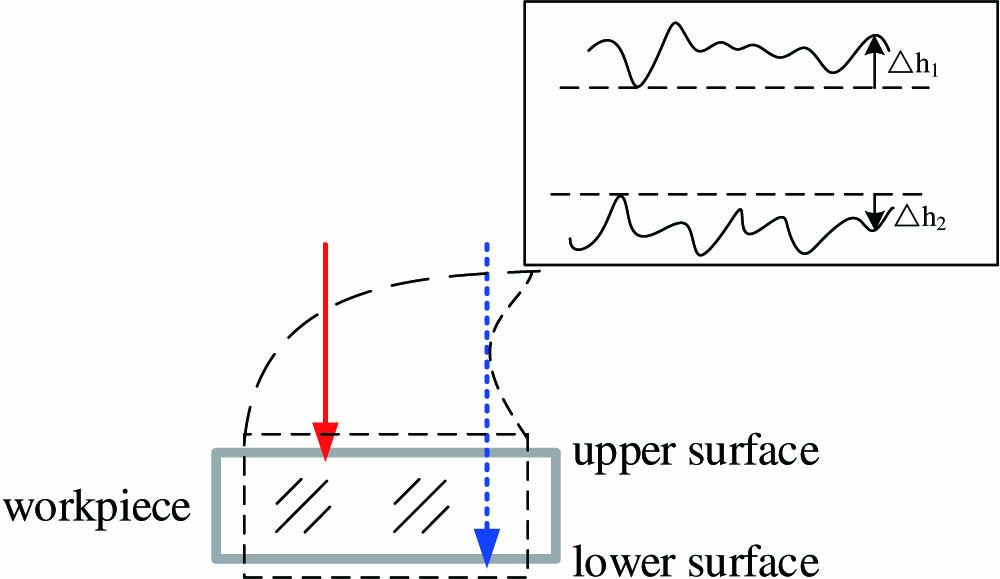
The schematic of self-interference (which is recognized as the method for real-time monitoring) is shown in Fig. 1. The beam that is reflected from the upper surface becomes the reference beam and the beam reflected from the lower surface within the cavity becomes the testing beam[12]. The optical path difference of the self-interference between the reference beam and testing beam is where and are the height differences between the real surface and basal plane figures of the workpiece, respectively; and are the refractive indices of the workpiece and air, respectively; and are the distributions of the optical path difference of the transmission and reflection that occur in the upper and lower surface figures of the monitoring plate, respectively; is the homogeneity of the material of monitoring plate; is the distribution of the optical path difference of the reflection that occurred in upper surface figure of the monitoring plate.
Consequently, Eq. (1) becomes Equation (3) shows that the surface figure of the workpiece can be measured through online self-interference testing. As the absolute reference plane, the upper surface figure of the monitoring plate (highly polished) is stable. The surface figure changes of the monitoring plate are considered from the lower surface in the polishing process and can be monitored by the self-interference fringe patterns between the upper and lower surface.
Compared to the online testing, the offline testing involves the reflection surface and transmission surface. A schematic of the optical path difference distribution of the offline testing[13] between the reference beam and testing beam in the reflection and transmission surface is shown in Fig. 2.
Figure 2.Optical path schematic of the offline testing; (a) reflection surface; (b) transmission surface.
The optical path difference of self-interference between the reference beam and testing beam in the reflection surface and transmission surface is where and are the distributions of the optical path difference (which is caused by the surface figure of the front and rear reference flat of the interferometer), respectively; is the air turbulence in the interference cavity; , , and are the distributions of the optical path difference of the transmission and reflection (which occurred in the upper and lower surface figures of the workpiece), respectively.
Consequently, Eqs. (4) and (5) become
The relationship of , , and can be solved by Eqs. (3), (7), and (8) when these conditions can be satisfied: (1) the monitoring plate has good, homogeneous structure (); (2) the surface figure of the front and rear reference flat in the interferometer is highly polished (, ); (3) the upper surface of the monitoring plate (polished) can be ignored (); (4) the air turbulence which is stable can be ignored () When and , Eq. (9) becomes There is a proportional relationship between the surface figure of the workpiece and the optical path difference according to phase-shifting interferometry. Consequently, Eq. (9) shows that the optical path difference of the reflection and transmission surface is always less than that of the self-interference surface.
A real-time monitoring system is set up for the surface of a polishing pad, as shown in Fig. 3. The monitoring system involves a dynamic interferometer connected to a computer and a beam expanding system (an adjustable beam reflecting system with a metal film coating). The diameter of the monitoring plate and workpiece is 260 mm and the thickness is 40 mm. The upper surface figure of the monitoring plate (highly polished) is 1/10 waves, waves, and parallelism is not more than 6 arcsec. The material is Nd-doped metaphosphate glass. The monitoring plate and workpiece are placed symmetrically and rotated to be in contact with the polishing pad within the ring. An essential instrument, a FizCam 2000EP laser dynamic interferometer of 4D technology employs a short coherence length laser (300 μm), the measurement wavelength is 659 nm, and the beam diameter is 100 mm[14,15].
Figure 3.Real-time monitoring system; (a) sideways-facing schematic of the monitoring system, (b) real monitoring system photograph.
The workpiece was measured with a real-time monitoring system in repeatability tests. The surface figure of the workpiece was measured each minute over the course of 30 min. The 30 measurements of the surface figure of the workpiece are shown in Fig. 4.
Figure 4 shows that the variable trend and value of the surface figure of the PV and power are stable; the online and real-time monitoring system can be applied for the monitoring experiment.
A schematic platform of the relative position of the monitoring plate and workpiece for the online testing experiment is shown in Fig. 5.
Figure 5.Schematic platform of the relative position of the monitoring plate and workpiece.
The online self-interference surface of the monitoring plate and the offline surface of the workpiece were measured with the real-time monitoring system and interferometer.
Figure 6.Variation trend of the monitoring plate and workpiece for online and offline testing in terms of PV; (a) self-interference and reflection surface; (b) self-interference and transmission surface.
Figure 6 shows that the variation trend of the monitoring plate is consistent with that of the workpiece in terms of PV. The PV of the online self-interference surface was always greater than that of the offline reflection and transmission testing.
Figure 7 shows that the offline testing of the surface figure of the monitoring plate is consistent with that of the workpiece in terms of power. The power of the online self-interference testing was always greater than that of offline reflection and transmission testing.
Figure 7.Variation trend of the monitoring plate and workpiece for online and offline testing in terms of power; (a) self-interference and reflection surface; (b) self-interference and transmission surface.
Figures 6 and 7 show the variation trends of the online testing data are consistent with the offline testing data. With the numeral deviation, there is the quantitative analysis for the variation trends of the surface figure for the online and offline testing data.
The relationship between the online self-interference and reflection and transmission surface is shown in Fig. 8. There is a gap between the online testing and offline testing except the proportionality relationship.
Figure 8.Proportional relationship of online and offline surface in terms of PV.
The surface figure and optical path differences are linear. However, the proportional variation cannot be in accordance with Eq. (10). Consequently, the friction heat and stress distribution in the polishing process in a workshop cannot be ignored and the upper surface figure of the monitoring plate is not desirable.
With the real-time monitoring system, the polishing machine would stop measurements in order to analyze the effects of the friction heat and stress variation in the polishing process after the online testing of the surface figure of the workpiece. The self-interference surface figure is measured each minute, a total of 40 times.
The value of the surface figure (of both the PV and power) decreases with the increase of downtime (shown in Fig. 9). Actually, Fig. 9 can find the friction and stress which result in the PV and power decrease (0.1 wave and 0.05 wave, respectively).
Figure 9.Variation of the surface figure in terms of the polishing heat and stress.
With the real-time monitoring system, the workpiece is placed horizontally because of the mirror in the real-time monitoring system and is placed vertically in offline testing. The surface figure is measured each minute, a total of 20 times.
Figures 10(a) and 10(b) show the surface figure of the horizontal and vertical placement of the workpiece. The PV for the horizontal placement is greater than 0.017 wave (in comparison to that for the vertical placement). The surface figure of the power is also greater than 0.028 wave (in comparison to that for the vertical placement).
Figure 10.Variation of the surface figure for the horizontal and vertical placement of the workpiece; (a) self-interference and reflection surface; (b) self-interference and transmission surface.
Figure 11 shows the gap of the optical path difference between the online self-interference testing and the offline reflection and transmission surface. The proportional relationship of the surface figure and optical path difference can be in accordance with Eq. (10). The external influence factor between the online testing and offline testing involves the expansion caused by temperature and humidity changes machine vibration, and air disturbance in the workshop. However, these factors can be ignored by repeatability tests of the real-time monitoring system.
Figure 11.Proportional relationship of the online and offline surface in terms of PV.
In conclusion, a method of real-time monitoring of the surface figure in continuous polishing is proposed. The variation trend of the online testing data is consistent with the offline testing data in terms of PV and power.
The numeral deviation in the surface figure of the workpiece results from the difference in the measurement principle in terms of self-interference, the reflection and transmission surfaces, the friction heat and stress distributions in polishing process, and placement of the workpiece in the measurement. Consequently, the upper surface figure of the monitoring plate and interferometer should be highly polished, the error should be reduced in online testing with the vibration isolation method, and the temperature and airflow fluctuations should be controlled with an air conditioner.
[12] D. Pileri, J. Hannon, D. A. Gildner, M. Baumler. Method and apparatus for real-time monitoring and feedback control of shape of a continuous planetary polishing surface. U.S. patent(1997).
[13] D. Malacara. Optical Shop Testing(2007).
[14] J. Millerd, N. Brock, J. Hayes, M. North-Mirris, M. Novak, J. Wyant. Proc. SPIE, 5531, 304(2004).
[15] B. Kimbrough, J. Millerd, J. Wyant, J. Hayes. Proc. SPIE, 6292, 62920F(2006).