• Opto-Electronic Advances
  • Vol. 5, Issue 8, 210029 (2022)
Fang Zhong1, Wei Hu1, Peining Zhu2, Han Wang3、4, Chao Ma1, Nan Lin1, and Zuyong Wang1、*
Author Affiliations
  • 1College of Materials Science and Engineering, School of Physics and Electronics, Hunan University, Changsha 410072, China
  • 2Hunan Aerospace Magnet & Magneto Co., LTD, Changsha 410200, China
  • 3State Key Laboratory of Precision Electronic Manufacturing Technology and Equipment, Guangzhou 510006, China
  • 4Jihua Laboratory, Foshan 528251, China
  • show less
    DOI: 10.29026/oea.2022.210029 Cite this Article
    Fang Zhong, Wei Hu, Peining Zhu, Han Wang, Chao Ma, Nan Lin, Zuyong Wang. Piezoresistive design for electronic skin: from fundamental to emerging applications[J]. Opto-Electronic Advances, 2022, 5(8): 210029 Copy Citation Text show less
    Piezoresistive designs for engineering electronic skin. (a) Developmental history of flexible skin-like electronics (e.g. milestones in the shear force measurement, large-area manufacturing, spatial mapping, bioinspired manufacturing, interconnection between e-skin and live neurons, and self-healing capability)10-17 . (b) Scheme illustrating the design and applications of piezoresistive sensors.
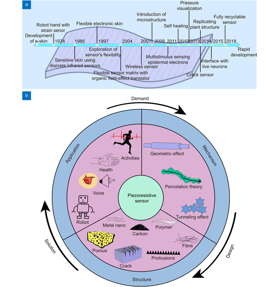
    Fig. 1. Piezoresistive designs for engineering electronic skin. (a) Developmental history of flexible skin-like electronics (e.g. milestones in the shear force measurement, large-area manufacturing, spatial mapping, bioinspired manufacturing, interconnection between e-skin and live neurons, and self-healing capability)10-17 . (b) Scheme illustrating the design and applications of piezoresistive sensors.
    Principles of piezoresistive effect. (a) Piezoresistance based on the geometric changes of metals and conducting polymers. i and ii represent the block and planar material geometries, respectively41,47. (b) Piezoresistance of semiconductor. Scheme illustrating the changes of charge carrier and energy band upon traction along the [111] direction in p–Si47. (c) Piezoresistance of composite materials based on the changes of conducting filler concentration and inter-filler distance48. (d) Structural piezoresistance based on the contact area and point changes of conducting architecture. Figure reproduced with permission from: (b) ref.47, Elsevier.
    Fig. 2. Principles of piezoresistive effect. (a) Piezoresistance based on the geometric changes of metals and conducting polymers. i and ii represent the block and planar material geometries, respectively41,47. (b) Piezoresistance of semiconductor. Scheme illustrating the changes of charge carrier and energy band upon traction along the [111] direction in p–Si47. (c) Piezoresistance of composite materials based on the changes of conducting filler concentration and inter-filler distance48. (d) Structural piezoresistance based on the contact area and point changes of conducting architecture. Figure reproduced with permission from: (b) ref.47, Elsevier.
    Development of piezoresistive sensors based on various materials. (a) Fabrication scheme and optical images of a hybrid metallic foam46. (b) Schematic illustrating the fabrication of CNTs/FKM nanocomposite50. FKM, fluoroelastomer; CNTs, carbon nanotubes; and TAIC, 1,3,5-triallyl-1,3,5-triazine-2,4,6 (1H,3H,5H)-trione. (c) Scheme illustrating the assembly of a MG/PU piezoresistive sensor51. MG, modified-graphite; PU, polyurethane; and PDMS, polydimethylsiloxane. (d) A flexible tactile sensor assembled from the 8x8 array of Si-strain gauges and the Si thin film transistors64. (e) Scheme illustrating the sandwich-structure of a PEDOT:PSS/Ag NW/PDMS component film74. PEDOT:PSS, poly(3,4-ethylenedioxythiophene):poly(styrenesulfonate); and Ag NWs: Ag nanowires. (f) mGN fillers form new conducting paths under pressure80. mGN, magnetic reduced graphene oxide@nickel nanowire. Figure reproduced with permission from: (a) ref.46, (f) ref.80, American Chemical Society; (c) ref.51, under a Creative Commons Attribution 4.0 International License; (d) ref.64, AIP Publishing.
    Fig. 3. Development of piezoresistive sensors based on various materials. (a) Fabrication scheme and optical images of a hybrid metallic foam46. (b) Schematic illustrating the fabrication of CNTs/FKM nanocomposite50. FKM, fluoroelastomer; CNTs, carbon nanotubes; and TAIC, 1,3,5-triallyl-1,3,5-triazine-2,4,6 (1H,3H,5H)-trione. (c) Scheme illustrating the assembly of a MG/PU piezoresistive sensor51. MG, modified-graphite; PU, polyurethane; and PDMS, polydimethylsiloxane. (d) A flexible tactile sensor assembled from the 8x8 array of Si-strain gauges and the Si thin film transistors64. (e) Scheme illustrating the sandwich-structure of a PEDOT:PSS/Ag NW/PDMS component film74. PEDOT:PSS, poly(3,4-ethylenedioxythiophene):poly(styrenesulfonate); and Ag NWs: Ag nanowires. (f) mGN fillers form new conducting paths under pressure80. mGN, magnetic reduced graphene oxide@nickel nanowire. Figure reproduced with permission from: (a) ref.46, (f) ref.80, American Chemical Society; (c) ref.51, under a Creative Commons Attribution 4.0 International License; (d) ref.64, AIP Publishing.
    Piezoresistive design and manufacture with singular structure. (a) Piezoresistance of an artificial structured sensor based on contact area changes91. ITO, indium tin oxide; PET, polyethylene terephthalate; SWCNTs, single-walled carbon nanotube; PDMS, polydimethylsiloxane. (b) Scheme illustrating the lotus-leaf-inspired piezoresistive design and assembly98. (c) Scheme illustrating the rose-petal-inspired piezoresistive design and assembly99 and the shark-skin-inspired piezoresistive design and assembly101. (d) Scheme illustrating the spider-leg-joint-inspired piezoresistive design with plenty of cracks102. Figure reproduced with permission from: (a) ref.91, (d) ref.102, Elsevier; (c) ref.101, Elsevier and ref.99, Royal Society of Chemistry.
    Fig. 4. Piezoresistive design and manufacture with singular structure. (a) Piezoresistance of an artificial structured sensor based on contact area changes91. ITO, indium tin oxide; PET, polyethylene terephthalate; SWCNTs, single-walled carbon nanotube; PDMS, polydimethylsiloxane. (b) Scheme illustrating the lotus-leaf-inspired piezoresistive design and assembly98. (c) Scheme illustrating the rose-petal-inspired piezoresistive design and assembly99 and the shark-skin-inspired piezoresistive design and assembly101. (d) Scheme illustrating the spider-leg-joint-inspired piezoresistive design with plenty of cracks102. Figure reproduced with permission from: (a) ref.91, (d) ref.102, Elsevier; (c) ref.101, Elsevier and ref.99, Royal Society of Chemistry.
    Sensitivities of different microstructure sensors. ITO, indium tin oxide; MWNT, multiwalled carbon nanotubes; and PDMS, polydimethylsiloxane. Figure reproduced with permission from ref.94, under a Creative Commons Attribution 4.0 International License.
    Fig. 5. Sensitivities of different microstructure sensors. ITO, indium tin oxide; MWNT, multiwalled carbon nanotubes; and PDMS, polydimethylsiloxane. Figure reproduced with permission from ref.94, under a Creative Commons Attribution 4.0 International License.
    Piezoresistive design and manufacture with hierarchical structure. (a) Multiple dome structures as piezoresistance sensing layer86. (b) Multiple structure comprising of dense protuberances and porous structure as piezoresistance sensing layer106. HPM, hybrid porous microstructure; and CNT, carbon nanotubes. (c) Piezoresistive sensitivities based on the sensing layers comprising of rough-to-rough, rough-to-flat and flat-to-rough surfaces107. Figure reproduced with permission from: (a) ref.86, (b) ref.106, (c) ref.107, American Chemical Society.
    Fig. 6. Piezoresistive design and manufacture with hierarchical structure. (a) Multiple dome structures as piezoresistance sensing layer86. (b) Multiple structure comprising of dense protuberances and porous structure as piezoresistance sensing layer106. HPM, hybrid porous microstructure; and CNT, carbon nanotubes. (c) Piezoresistive sensitivities based on the sensing layers comprising of rough-to-rough, rough-to-flat and flat-to-rough surfaces107. Figure reproduced with permission from: (a) ref.86, (b) ref.106, (c) ref.107, American Chemical Society.
    Design and manufacture of fibre piezoresistive sensor. (a) Schematic of a rGO-Ag NW@cotton fibre, through immersion of cotton fibres in a reductive solution containing GO and AgNW112. GO, graphene oxide; rGO, reduced GO; and AgNW, Ag nanowires. (b) Scheme of an electrospun fibre piezoresistive sensor and its sensing mechanisms during pressure and blending110. KL, kraft lignin. (c) Scheme of a wet-spinning single-fibre piezoresistive sensor122. Figure reproduced with permission from: (a) ref.110, (b) ref.112, Elsevier; (c) ref.122, American Chemical Society.
    Fig. 7. Design and manufacture of fibre piezoresistive sensor. (a) Schematic of a rGO-Ag NW@cotton fibre, through immersion of cotton fibres in a reductive solution containing GO and AgNW112. GO, graphene oxide; rGO, reduced GO; and AgNW, Ag nanowires. (b) Scheme of an electrospun fibre piezoresistive sensor and its sensing mechanisms during pressure and blending110. KL, kraft lignin. (c) Scheme of a wet-spinning single-fibre piezoresistive sensor122. Figure reproduced with permission from: (a) ref.110, (b) ref.112, Elsevier; (c) ref.122, American Chemical Society.
    Piezoresistive design and manufacture with spongy structure. (a) Freeze drying for the fabrication of piezoresistive sponge68. (b) Directional freeze drying of the fabrication of piezoresistive wave-shaped sensing layers127. CNC, cellulose nanocrystals. (c) Dip coating of as-fabricated sponge with conducting materials130. PU, polyurethane; and MWCNT, multiwalled carbon nanotubes. (d) Sacrificial template for the fabrication of piezoresistive sponge131. (e) Sponge-based hierarchical structure (e.g. cracks) for piezoresistive sensor134. Figure reproduced with permission from: (a) ref.68, (d) ref.131, (e) ref.134, American Chemical Society; (b) ref.127, (c) ref.130, Royal Society of Chemistry.
    Fig. 8. Piezoresistive design and manufacture with spongy structure. (a) Freeze drying for the fabrication of piezoresistive sponge68. (b) Directional freeze drying of the fabrication of piezoresistive wave-shaped sensing layers127. CNC, cellulose nanocrystals. (c) Dip coating of as-fabricated sponge with conducting materials130. PU, polyurethane; and MWCNT, multiwalled carbon nanotubes. (d) Sacrificial template for the fabrication of piezoresistive sponge131. (e) Sponge-based hierarchical structure (e.g. cracks) for piezoresistive sensor134. Figure reproduced with permission from: (a) ref.68, (d) ref.131, (e) ref.134, American Chemical Society; (b) ref.127, (c) ref.130, Royal Society of Chemistry.
    Additive manufacturing for piezoresistive sensor. (a) Drop-on-demand material jetting for the facial fabrication of piezoresistive structures143. MCF, milled carbon fibers; and SR, silicone rubber. (b) 3D printing of human-skin-inspired texture as piezoresistive sensing layers144. CNT, carbon nanotube. (c) Application of a 3D printed piezoresistive sensor for robotic fingertips to sense force145. (d) 3D printing of conducting composite for piezoresistive sensor148. SIS, polystyrene–polyisoprene–polystyrene. (e, f) 3D printing of different structure parameters (e.g. diameter, interaxial angle, and interlayer space) for piezoresistive sensor149. GF, gauge factor. Figure reproduced with permission from: (a) ref.143, (e, f) ref.149, Elsevier; (c) ref.145, American Chemical Society; (d) ref.148, Royal Society of Chemistry.
    Fig. 9. Additive manufacturing for piezoresistive sensor. (a) Drop-on-demand material jetting for the facial fabrication of piezoresistive structures143. MCF, milled carbon fibers; and SR, silicone rubber. (b) 3D printing of human-skin-inspired texture as piezoresistive sensing layers144. CNT, carbon nanotube. (c) Application of a 3D printed piezoresistive sensor for robotic fingertips to sense force145. (d) 3D printing of conducting composite for piezoresistive sensor148. SIS, polystyrene–polyisoprene–polystyrene. (e, f) 3D printing of different structure parameters (e.g. diameter, interaxial angle, and interlayer space) for piezoresistive sensor149. GF, gauge factor. Figure reproduced with permission from: (a) ref.143, (e, f) ref.149, Elsevier; (c) ref.145, American Chemical Society; (d) ref.148, Royal Society of Chemistry.
    Piezoresistive sensor for health monitoring. (a) Detection of physical activities by piezoresistive sensor, including the swallowing (A and B: the pharyngeal and esophageal phase, respectively) and the posture of human back152. (b) Detection of physiological activities (e.g. wrist and jugular venous pulse) at high sensitivities153. (c) Detection of myocardic activities (e.g. heartbeats at breathing and not breathing) by a piezoresistive sensor154. (d) Identification of different mechanical stimuli, including pressure, shear and torsion force132. Figure reproduced with permission from: (a) ref.152, (d) ref.132, Elsevier; (b) ref.153, (c) ref.154, American Chemical Society.
    Fig. 10. Piezoresistive sensor for health monitoring. (a) Detection of physical activities by piezoresistive sensor, including the swallowing (A and B: the pharyngeal and esophageal phase, respectively) and the posture of human back152. (b) Detection of physiological activities (e.g. wrist and jugular venous pulse) at high sensitivities153. (c) Detection of myocardic activities (e.g. heartbeats at breathing and not breathing) by a piezoresistive sensor154. (d) Identification of different mechanical stimuli, including pressure, shear and torsion force132. Figure reproduced with permission from: (a) ref.152, (d) ref.132, Elsevier; (b) ref.153, (c) ref.154, American Chemical Society.
    Piezoresistive sensor for intelligent healthcare. (a) Piezoresistance for visiual, alarm, wireless and implanted applications35. (b) Triode-mimicking pressure sensor for intelligent shoe pad159. (c) Scheme illustrating a monitoring system developed based on the intelligent shoe pad in (b)159. (d) Continuous and multiple signals from the integrated gait monitoring system in (c)159. Figure reproduced with permission from: (a) ref.35; (b–d) ref.159, American Chemical Society.
    Fig. 11. Piezoresistive sensor for intelligent healthcare. (a) Piezoresistance for visiual, alarm, wireless and implanted applications35. (b) Triode-mimicking pressure sensor for intelligent shoe pad159. (c) Scheme illustrating a monitoring system developed based on the intelligent shoe pad in (b)159. (d) Continuous and multiple signals from the integrated gait monitoring system in (c)159. Figure reproduced with permission from: (a) ref.35; (b–d) ref.159, American Chemical Society.
    Piezoresistive sensor for intelligent speech recognition. (a) Piezoresistive detection of sound (e.g. word recognition, volume detection, and voice recognition)68. (b) Response of a MXene-based piezoresistive sensor to the audio outputs at different volumes162. (c) Anti-interference voice recognition by a skin-attachable piezoresistive sensor165. Figure reproduced with permission from: (a) ref.68, (b) ref.162, (c) ref.165, American Chemical Society.
    Fig. 12. Piezoresistive sensor for intelligent speech recognition. (a) Piezoresistive detection of sound (e.g. word recognition, volume detection, and voice recognition)68. (b) Response of a MXene-based piezoresistive sensor to the audio outputs at different volumes162. (c) Anti-interference voice recognition by a skin-attachable piezoresistive sensor165. Figure reproduced with permission from: (a) ref.68, (b) ref.162, (c) ref.165, American Chemical Society.
    Piezoresistive sensor for prosthetics and robots. (a) Manipulating the robot arm by a piezoresistive sensor for music playing169. (b) Large-area force distribution detected by fibre piezoresistive sensor array171. (c) Piezoresistive sensor for the real-time monitoring of robot−tissue collision/interaction in surgical robots173. (d) Development of an artificial afferent nerve based on multiple piezoresistive sensors175. Figure reproduced with permission from: (a) ref.169, (b) ref.171, (c) ref.173, American Chemical Society.
    Fig. 13. Piezoresistive sensor for prosthetics and robots. (a) Manipulating the robot arm by a piezoresistive sensor for music playing169. (b) Large-area force distribution detected by fibre piezoresistive sensor array171. (c) Piezoresistive sensor for the real-time monitoring of robot−tissue collision/interaction in surgical robots173. (d) Development of an artificial afferent nerve based on multiple piezoresistive sensors175. Figure reproduced with permission from: (a) ref.169, (b) ref.171, (c) ref.173, American Chemical Society.
    StructureMaterialsSensor thicknessPerformanceFlexible/ stretchableApplication/ Force applicationFabrication techniqueRef.
    Sensitivity or GFSensing rangeResponse timeCyclic test
    GF: gauge factor (in some case just a single-point value). CNTs: carbon nanotubes; FKM: fluoroelastomer; SiC: silicon carbide; MWCNTs: multi-walled carbon nanotubes; Si: silicone; CB: carbon black; PDMS: polydimethylsiloxane; rGO: reduced graphene oxide; PS: polystyrene; VGr: vertical graphene; Ag NW: silver nanowire; PI: polyimide; Ag: silver; CSilkNM: carbonized silk nanofiber membranes; PPy: polypyrrole; EVOH: poly(vinyl alcohol-co-ethylene); POE: polyolefin elastomer; NiNWs: nickel nanowires; SWCNTs: single walled carbon nanotubes; Gr: graphene; ACNT: aligned carbon nanotub; Pt: platinum; PUA: polyurethane acrylate; PU: polyurethane; CNCs: cellulose nanocrystals; SiNPs: silica nanoparticles; TPU: thermoplastic polyurethane; CB: carbon black; PANI: polyaniline; PEDOT:PSS: poly(3,4-ethylenedioxythiophene):poly(styrenesulfonate); WGF: wrinkled graphene film; and PVA: polyvinyl alcohol
    Simple “bulk”Simple “bulk”CNTs/FKM100 ~ 300 mm1.3 ×105 (ε = 100%)232% ε500 times Hysteresis (0~150% ε)Yes/YesStrain/Human motion monitoring and Stretchable LEDsInternal melt-mixerref.50
    Simple “bulk”SiC/Ecoflex2.47×105 (ε = 2.5%)0.05% ~ 5% ε10000 times Consistent (0~4% ε)Yes/YesStrain and pressure/Health and motion monitoringLaser direct writingref.65
    Simple “bulk”rGO/PS~ 60 mm250 (ε = 1.05%)100 ms2000 times Consistent (0~0.7% ε)Yes/YesPressure/Human movement behaviorsLaser scriberef.152
    Simple “bulk”VGr/PDMS72(ε = 20%) 22000 (ε = 100%)ε = 100% (Max)1000 times Consistent (0~40% ε)Yes/YesStrain/Human’s activities and timbresDepositionref.164
    FibreFibrerGO-Ag NW@cotton fiber4.23 kPa−1 (P =2.0 kPa)220 msYes/YesPressure, bending and twisting/Finger motion and pulse monitoringCoatingref.112
    Nano fibrePI@Ag1400 kPa−1 (5~100 kPa)100 Pa ~ 100 kPa200 ms1000 times Consistent (5 kPa)Yes/YesPressure/Movement of body and temperatureElectrospinning and in situ growthref.66
    Nano fibreCSilkNM0.63 ± 0.14 mm34.47 kPa−1 (0.8 ~ 400 Pa)0.8 Pa ~ 5 kPa16.6 ms10000 times Consistent (2.5 kPa)Yes/YesPressure/Human physiology monitoring and pressure distributionElectrospinningref.115
    FibreMWCNT/Si /EcoFlex1.35 mm1378 (ε=330%)50% ~ 300% ε295ms10000 times Consistent (0~1000% ε)Yes/YesStrain, bending and torsion /Human motion detectionWet spinningref.122
    Nano fibrePPy/EVOH/ POE~ 70 μm2.83 kPa−1 (0 ~17 kPa)Upper limit 80 kPa3 ms4500 times Consistent (0~10 kPa)Yes/YesPressure/Large area pressure sensingDirect melt extrusionref.171
    Surface structureMicro-domerGO@NiNWs/ EcoFlex1302.1 kPa−1 (0 ~ 2.5 kPa)72 Pa ~ 20 kPa6 ms20000 times ConsistentYes/YesPressure/Health and motion monitoringHot embossingref.80
    PyramidSWCNTs/ PDMS~ 700 mm8655.6 kPa−1 (400 ~ 800 Pa)Lower limit 7.3 Pa4 ms10000 times ConsistentYes/NoPressure/Health carePhotolithographyref.91
    PyramidPDMS/Carbon~ 1 mm−2.5 kPa−1 (0 ~ 160 Pa)15 Pa ~ 9 kPa~20 msYes/NoPressure/Human movement behaviorsLaserref.7
    HierarchicalPDMS/Gr~ 1 mm1.2 kPa−1 (0.2 ~ 25 kPa)5 Pa ~12 kPa1000 times Consistent (1, 5, and 10 kPa)Yes/NoPressure /Human movement behaviors and voice recognitionSoft lithographyref.98
    Micro-papillaeCu - Ag NWs/ PDMS~ 1 mm1.35 kPa−1 (0 ~ 2.0 kPa)2 Pa ~ 20 kPa36 ms5000 times Consistent (0 ~2 kPa)Yes/NoPressure/Human physiology monitoringSoft lithographyref.99
    HierarchicalACNT/Gr/ PDMS~ 500 mm19.8 kPa−1 (0.6 ~ 300 Pa)0.6 Pa ~ 5.8 kPa16.7 ms35000 times Consistent (0~ 150 Pa)Yes/NoPressure, bending and torsional/Voice recognitionSoft lithographyref.100
    Surface structureCrackPt/PUA~ 10 mm2, 000 (ε = 2%)Yes/YesStrain/Human movement behaviors and voice recognitionDepositing/Stretchingref.15
    CrackGold/PDMS100 μm200 (ε <0.5) 1000 (0.5% < ε < 0.7%) 5000 (0.7% < ε < 1%)2% εYes/YesStrain and pressure/Human physiology monitoring and sound vibrationsDepositing/ Stretchingref.104
    Skin TextureCNTs/PDMS2.08 kPa−1 (0.12 kPa)50 ms8000 times ConsistentYes/YesPressure/Human movement behaviors3D-printingref.144
    PapillaeSWNT- MXene11.47 kPa−1 (13 Pa ~ 0.77 kPa)(13 Pa ~ 10 kPa)20 ms10000 times Consistent (0~ 1 kPa)Yes/NoVoice recognition (different volumes)/PressureEtching and exfoliationref.162
    CracksrGO/PDMS~ 300 μm8699 (0.8 ~ 1.0% ε)0.000064% (Mim)107 ms1000 times Consistent (0~0.35% ε)Yes/YesAnti-interference voice recognition/PressureFemtosecond laser direct writingref.165
    PorousPorousPU/Liquid metal> 25202 msYes/YesPressure/Electronic protection foam for transportationCoatingref.46
    PorousMxenes /rGO22.56 kPa−1 (1 kPa ~ 3.5 kPa)Lower limit 10 Pa<200 ms1000 times Consistent (0~ 0.81 kPa)Yes/YesPressure/Human physiology monitoring and voice recognitionIce - template freezinref.68
    MultilayerMxenes/CNCs114.6 kPa −1 (0.05 ~ 10 kPa)Lower limit 1.0 Pa189 ms2000 times Consistent (0~50% ε)Yes/YesPressure/Human physiology monitoring and voice recognitionDirectional freezingref.127
    PorousGr/PDMS0.09 kPa−1 (0 ~ 1000 kPa)Upper limit 2000 kPa100 msYes/YesPressure/Human physiology and motion monitoringSacrificial templateref.131
    PorousGr/PDMS~0.3 mm15.9 kPa−1 (0 ~ 60 kPa)1.2 msYes/YesPressure and bending/Human physiology monitoring and intelligent robotsSacrificial templateref.82
    PorousCNTs/ SiNPs/ Si elastomer polymer9.5 mm0.096 kPa−1 (0 ~ 175 kPa)10000 times Consistent (0~ 20 kPa)Yes/NoPressure/Human movement behaviors and intelligent robots3D - printingref.145
    PorousTPU/CB5.54 kPa−1 (10 Pa ~ 800 kPa)10 Pa ~ 800 kPa20 ms10000 times Consistent (40~200 kPa)Yes/NoPressure/Human physiology monitoring and voice recognition3D - printingref.147
    PorousTPU/CB1.12 kPa−1 (20 Pa ~ 60 kPa)20 Pa ~ 1.2 MPa15 ms10000 times Consistent (0~ 30 kPa)Yes/YesPressure/Human health and intelligent robotsSacrificial templateref.153
    PorousMultilayerGr/Ecoflex4.68 kPa−1 (0 ~ 150 kPa) 11.09 kPa−1 (150 ~ 200 kPa)Upper limit 200 kPa1000 times Consistent (0~ 200 kPa)Yes/YesPressure/Physiological signal detectionLaser scriberef.159
    MultilayerTi3C2 -MXene/PI180.1 ~ 94.8 (0.19 ~ 0.82% ε)30 ms4000 times Consistent (0~ 7.5 kPa)Yes/YesPressure and strain/Human’s activitiesEtchingref.160
    MultilayerGO/Gr0.032 kPa−1 (< 1 kPa)8000 times ConsistentYes/YesHuman computer interaction/PressureUltrasonicref.169
    Combined structuresHybridAgNWs/ PDMS128.29 kPa−1 (0 ~ 200 Pa) 1.28 kPa−1 (0.2 ~ 10 kPa)2.5 Pa ~ 8 0 kPa<100 ms10000 times Consistent (0~ 10 kPa)Yes/NoPressure/Human physiology monitoring and voice recognitionLaser etchingref.86
    Textured@PorousCNTs/PDMS~ 1 mm83.9 kPa −1 (<140 Pa)0.5 Pa ~ 10 kPa170 ms29000 times ConsistentYes/NoPressure/Human physiology monitoring and voice recognitionSoft lithography/ sacrificial templateref.106
    Conical frustum-like structuresAg/PDMS259.32 kPa −1 (0.36 Pa ~ 2.5 kPa)0.36 Pa - 54 kPa200 μs1000 times Consistent (0~ 0.47 kPa)Yes/NoPressure/Health monitoring and intelligent robotsLithography/Depositionref.107
    Crack @PorousPANI/PDMS~ 300 mm~0.055 kPa−1 (4 Pa ~ 5 kPa) 10 (ε = 25%)Lower limit 4 Pa60 ms500 times Hysteresis (0~5% ε)Yes/YesPressure, strain, shear and torsion/Human movement behaviorsSacrificial template /Stretchingref.132
    Crack @PorousGold@PU59 ~ 122 Pa−1 (0 ~ 14.2 kPa)Lower limit 0.568 Pa9 ms1000 times Consistent (0~45% ε)Yes/YesPressure/Voice recognition and vehicle speed calculationIon sputtering/ Compressref.134
    OthersSandwichPEDOT:PSS/ AgNWs/ PDMS1 mm8.0 (ε = 40%)50% ε (Max)300 times Consistent (0~30% ε)Yes/YesStrain/Finger motionsTransfer - printing techniqueref.74
    SandwichWGF/PVA/PI4.52kPa−1 (0 ~ 3 kPa) 28.34kPa−1 (3 ~ 10 kPa)2.24 Pa ~14 kPa87 ms6000 times ConsistentYes/YesPressure/Human movement behaviorsElectrospinning and ink - jet printref.117
    Table 1. Summary on the parameters of current piezoresistive sensors.
    Fang Zhong, Wei Hu, Peining Zhu, Han Wang, Chao Ma, Nan Lin, Zuyong Wang. Piezoresistive design for electronic skin: from fundamental to emerging applications[J]. Opto-Electronic Advances, 2022, 5(8): 210029
    Download Citation