• Photonics Research
  • Vol. 3, Issue 4, 133 (2015)
[in Chinese]1, [in Chinese]1, [in Chinese]1, [in Chinese]1, [in Chinese]1、*, [in Chinese]1, [in Chinese]2, and [in Chinese]1
Author Affiliations
  • 1National Laboratory of Solid State Microstructures, Collaborative Innovation Center of Advanced Microstructures and College of Engineering and Applied Sciences, Nanjing University, Nanjing 210093, China
  • 2Center for Display Research, Department of Electronic and Computer Engineering, Hong Kong University of Science and Technology, Clear Water Bay, Kowloon, Hong Kong, China
  • show less
    DOI: 10.1364/PRJ.3.000133 Cite this Article Set citation alerts
    [in Chinese], [in Chinese], [in Chinese], [in Chinese], [in Chinese], [in Chinese], [in Chinese], [in Chinese]. Arbitrary and reconfigurable optical vortex generation: a high-efficiency technique using director-varying liquid crystal fork gratings[J]. Photonics Research, 2015, 3(4): 133 Copy Citation Text show less
    Schematic diagram and diffraction property of a director-varying LC fork grating with m=1. The color variation from blue to red indicates the director varying from 0 to π continuously, and the gray sticks label the local director orientations. The polarization vectors observed along the light propagation direction are marked with arrows. LCP, left circularly polarized; LP, linearly polarized; RCP, right circularly polarized.
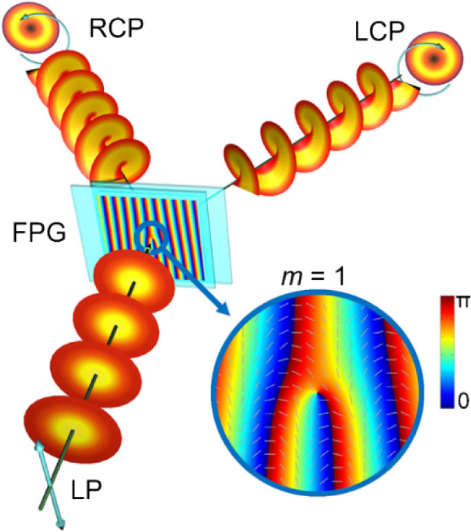
    Fig. 1. Schematic diagram and diffraction property of a director-varying LC fork grating with m=1. The color variation from blue to red indicates the director varying from 0 to π continuously, and the gray sticks label the local director orientations. The polarization vectors observed along the light propagation direction are marked with arrows. LCP, left circularly polarized; LP, linearly polarized; RCP, right circularly polarized.
    DMD-based micro-lithography setup consists of a light emission component, a dynamic pattern generation component, an image focusing component, and a monitor component. Three out of all 18 exposure sum-regions from FPGs with m=2, as well as with m=1 and p=1, are shown as examples, with corresponding polarizer angles listed below.
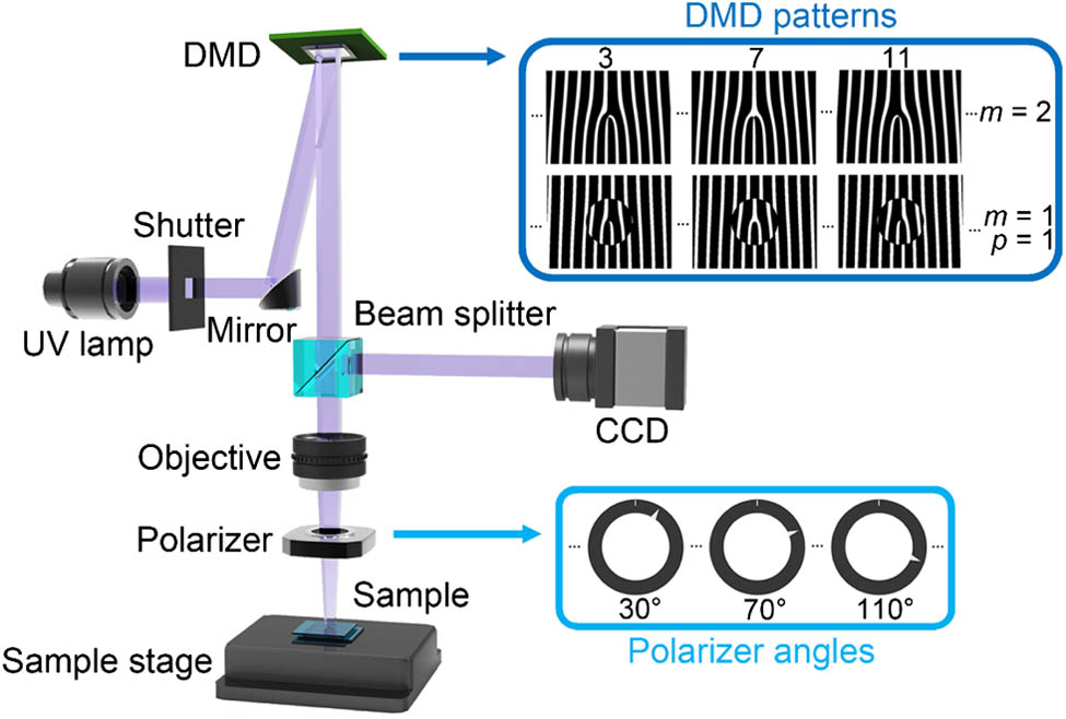
    Fig. 2. DMD-based micro-lithography setup consists of a light emission component, a dynamic pattern generation component, an image focusing component, and a monitor component. Three out of all 18 exposure sum-regions from FPGs with m=2, as well as with m=1 and p=1, are shown as examples, with corresponding polarizer angles listed below.
    (a) Theoretical, (b) measured director distribution, and (c) POM micrograph of an FPG with m=2. (d) Micrograph of a reconfigured FPG with m=10. The color bars indicate the director varying from 0 to π continuously, and the scale bars are all 100 μm.
    Fig. 3. (a) Theoretical, (b) measured director distribution, and (c) POM micrograph of an FPG with m=2. (d) Micrograph of a reconfigured FPG with m=10. The color bars indicate the director varying from 0 to π continuously, and the scale bars are all 100 μm.
    Dependencies of diffraction efficiency on (a) applied voltage and (b) incident polarization at 2.31 Vrms. Top images are the diffraction patterns on different polarization conditions marked with circles in corresponding color on the curves. The color bar indicates the relative optical intensity in all diffraction patterns.
    Fig. 4. Dependencies of diffraction efficiency on (a) applied voltage and (b) incident polarization at 2.31Vrms. Top images are the diffraction patterns on different polarization conditions marked with circles in corresponding color on the curves. The color bar indicates the relative optical intensity in all diffraction patterns.
    Theoretical director distributions, micrographs, measured director distributions, and diffraction patterns of samples with (a) m=1 and p=1, (b) m=1 and p=2, (c) m=2.5, and (d) m=2.5 and p=1. The scale bars are all 100 μm. Incident polarizations are labeled in the images; clockwise/counterclockwise indicates left/right circularly polarized light.
    Fig. 5. Theoretical director distributions, micrographs, measured director distributions, and diffraction patterns of samples with (a) m=1 and p=1, (b) m=1 and p=2, (c) m=2.5, and (d) m=2.5 and p=1. The scale bars are all 100 μm. Incident polarizations are labeled in the images; clockwise/counterclockwise indicates left/right circularly polarized light.
    [in Chinese], [in Chinese], [in Chinese], [in Chinese], [in Chinese], [in Chinese], [in Chinese], [in Chinese]. Arbitrary and reconfigurable optical vortex generation: a high-efficiency technique using director-varying liquid crystal fork gratings[J]. Photonics Research, 2015, 3(4): 133
    Download Citation