Abstract
A high-efficiency technique for optical vortex (OV) generation is proposed and demonstrated. The technique is based on liquid crystal fork gratings with space-variant azimuthal orientations, which are locally controlled via polarization-sensitive alignment layers. Thanks to the optical rewritability of the alignment agent and the dynamic image generation of the digital micro-mirror device, fork gratings can be instantly and arbitrarily reconfigured. Corresponding optical vortices carrying arbitrary azimuthal and radial indices are demonstrated with a conversion efficiency of 98.5%, exhibiting features of polarization control and electrical switching. The technique may pave a bright road toward OV generation, manipulation, and detection.1. INTRODUCTION
Optical vortices (OVs), commonly characterized by a phase singularity and a helical phase front, have gained considerable interest in a variety of fields over the past two decades [1]. Their screw-type phase distribution results in an orbital angular momentum (OAM) of per photon [1], wherein represents the topological charge, meaning how many twists the light performs in one wavelength. OAM, theoretically capable of having an infinite number of states, adds another degree of freedom in the manipulation of light. Owing to the abundant vortical states, OAM-based space-division multiplexing could drastically enhance the bandwidth of optical communication [2–4]. OVs are also utilized in quantum computation [5] and communication [6–8], which use the multistate of light to encode information. OAM induces a torque on an electric dipole, thereby making rotational motion possible [9]. This leads to applications such as optical tweezers, nanostructure fabrications, and OAM-driven micromachines [10,11]. In addition to the fields mentioned above, OVs could also be utilized in astronomical observations [12].
A more general description of OVs is the so-called Laguerre–Gaussian (LG) mode [1,13]. LG modes have two featured indices: and , which are the azimuthal (i.e., the topological charge) and the radial indices, respectively. Most literature on the applications of OVs is based on LG modes with , which exhibits a donut-like intensity distribution owing to the phase singularity at the beam axis [1]. When is a positive integer, the mode presents concentric rings. These multiringed modes have attracted much attention over the past few years. More specifically, they are considered to be suitable tools for the trapping of cold atoms [14] and gravitational wave detection [15]. More recently, OVs with fractional values [16] have been intensively studied for their great potential in high-dimensional quantum entanglement [17,18].
The capability of generating high-quality OVs is crucial for all of the above applications. So far, several means have been employed for OV generation. In initial studies, a pair of cylindrical lenses was used to rotate a Hermite–Gaussian beam to form the helical phase [1]. Afterward, OVs were usually converted from Gaussian beams directly rephased by spiral phase plates [19,20] or converted via q-plates [21,22]. However, these methods work only for a fixed conversion mode and a given wavelength, or are only suitable for simple LG mode () generation. Another alternative strategy is a computer-generated hologram (CGH), which consists of a diffraction grating with centric dislocations, namely a “fork” grating [23,24]. The fork grating can convert a Gaussian beam into a series of OVs with opposite twist directions. This approach could be accomplished through patterned electrodes [25] or polymer dispersed liquid crystals (LCs) [26]. These vortex generators exhibit excellent tunability. However, the geometry of the fork gratings is static, and thus the resultant is fixed. To arbitrarily refresh the CGHs, the spatial light modulator (SLM) was introduced [27,28]. Unfortunately, this technique suffers from several shortcomings: first, the pixel size of the SLM (typically [29]) is too large, making the chip size mismatch with the incident beam. Second, the diffraction efficiency of the SLM, which is usually based on phase modulation, is limited to 20% [30]. Third, a complex electrode matrix is required to drive the discrete pixels separately [29], and thus background diffraction is unavoidable. These drawbacks make the strategy costly, optically inefficient, and of limited quality. Hence, exploring new high-efficiency approaches for arbitrary and reconfigurable OV generation is in urgent demand.
Sign up for Photonics Research TOC. Get the latest issue of Photonics Research delivered right to you!Sign up now
Accordingly, we have developed a digital micro-mirror device (DMD) based micro-lithography setup to inscribe micro-patterns into LC cells coated with polarization-sensitive photoalignment layers [31]. Afterward, high-quality LC binary fork gratings with single OV conversion efficiency up to 37.5% were demonstrated [32]. To further improve the efficiency, a promising method is introducing the Pancharatnam–Berry (PB) phase [33,34], which features a spatially modulated polarization distribution. Such a PB phase could be achieved by recording polarization holograms in a polarization-sensitive medium via the interference of two orthogonal circularly polarized beams [35,36]. Theoretically, the input energy could be 100% diffracted into a single order for such optical devices. A similar strategy has been introduced to generate OVs via LC forked polarization gratings (FPGs, i.e., director-varying LC fork gratings), which are obtained through polarization interference between a Gaussian beam and a vortex beam [37,38]. However, the intensity distribution mismatch between the two beams remarkably spoils the quality of the generated polarization holograms. Moreover, the technique was only applied to specific OVs (with small and ), which restricts its applications. Herein, by means of DMD-based micro-lithography, FPGs with continuously space-variant director distributions are fabricated via multistep, partly overlapping exposures synchronized with polarizer rotation. OVs carrying integral or fractional with and without are demonstrated in high efficiency and capable of being instantly reconfigured. Furthermore, they exhibit the important features of polarization control and electrical switching. The proposed technique supplies a universal and practical approach for OV generation, with crucial requirements of high efficiency as well as instant and arbitrary reconfiguration satisfactorily settled.
2. PRINCIPLE
An FPG is essentially an inhomogeneous waveplate, like a combination of polarization gratings (PGs) and q-plates. For a simple FPG with only an azimuthal index , the LC directors are homogeneous along the axis and obey the following equation in the plane [38]:
In Eq. (1), the first term on the right-hand side describes a q-plate, where denotes the topological charge and exhibits the local azimuthal angle in the plane. The second term describes a PG, where Λ is the pitch of the grating. is the initial azimuthal angle and is usually assumed to be zero as it does not affect the resultant OAM. According to Eq. (1), the director distribution of an FPG with is calculated and shown as the bottom-right image in Fig. 1. The color variation from blue to red indicates the director varying from 0 to continuously, with gray sticks marking the local director orientations. For the more general cases, a new term corresponding to the radial index should be considered. Consistent with the helical phase pattern of LG beams with [28], the director distributions follow where represents a unit step function, represents the generalized Laguerre polynomial, , and represents the output beam-waist radius. Owing to the change of sign of the associated Laguerre polynomial, there exist circular discontinuities, where the director is shifted by .
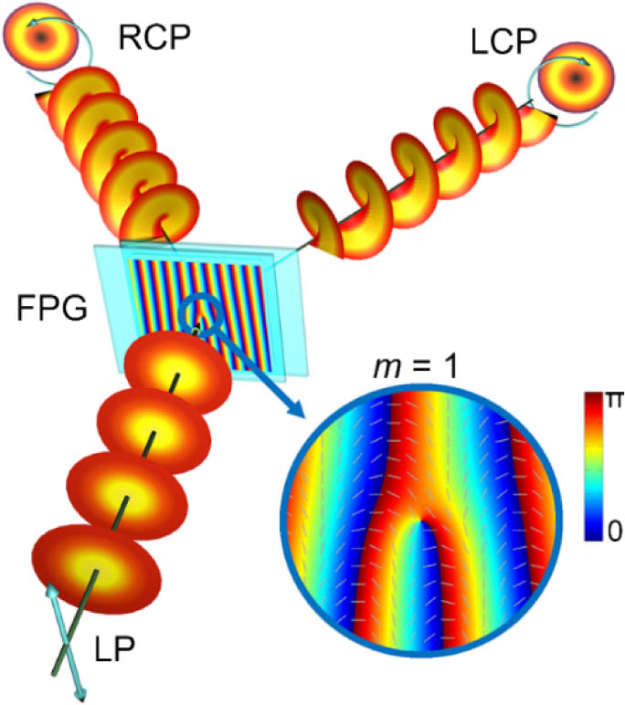
Figure 1.Schematic diagram and diffraction property of a director-varying LC fork grating with . The color variation from blue to red indicates the director varying from 0 to continuously, and the gray sticks label the local director orientations. The polarization vectors observed along the light propagation direction are marked with arrows. LCP, left circularly polarized; LP, linearly polarized; RCP, right circularly polarized.
When the FPGs are illuminated by a Gaussian beam, the far-field Fraunhofer patterns turn to vortices carrying the corresponding topological and radial indices. The diffraction property can be obtained through Jones matrix calculation [38]. Under the paraxial approximation, the Jones matrix for such an FPG is given by
Here is the identity matrix, is the normalized retardation (i.e., half of the phase retardation ), is the LC birefringence, is the LC cell gap, and is the free-space wavelength. The two-dimensional spatially varying LC directors of more general FPGs follow Eq. (2). Then, consider a circularly polarized incident beam with electric field , where are the two spin eigenstates, corresponding to right (+) and left (−) circular polarization states. The near-field electric field of emerging light is represented as
The far-field electric field of the th diffraction order can be summarized as
Therefore, the diffraction efficiency . We obtain where is the fraction of the input power in each spin eigenstate, being the normalized input wave function. Note that , the normalized Stokes parameter corresponding to the fraction of incident circular polarization.
From the calculation, it can be seen that the FPG has only three diffraction orders: st orders, which are always circularly polarized and orthogonal to each other with OAM of opposite and identical values, and zeroth order, which is a Gaussian mode with the same polarization as the input beam. The intensity distribution among the three orders depends on the phase retardation and the incident polarization. By adjusting the phase retardation, switching between Gaussian beams and OVs can be realized. If the phase retardation equals , the incident linearly polarized light will equally diffract to the st orders. As shown in Fig. 1, incident light is totally converted to the two output OVs with through an director-varying fork grating. If the input light is circularly polarized, only one OV with orthogonal circular polarization will be obtained. In this manner, we can accomplish a dynamic energy distribution between the st orders by tuning the incident polarization. The design can be applied to arbitrary OV generation, including OVs with even when is a fraction.
3. FABRICATION
To realize the above design in a LC cell, a photoalignment technique based on dynamic micro-lithography was employed. Photoalignment is quite suitable for high-resolution multidomain alignment of LCs compared to the rubbing technique [39]. Here we used a sulphonic azo-dye SD1 (Dai-Nippon Ink and Chemicals, Japan) as the alignment agent. Indium–tin–oxide (ITO) coated glass substrates were ultrasonically bathed, UV-Ozone cleaned, and then spin-coated with a 0.5% solution of SD1 in dimethylformamide. 6 μm spacers were spurted over one SD1-coated substrate, and then the counter substrate was covered. They were assembled together and sealed with epoxy glue to form the cell. SD1 molecules are sensitive to the polarization of incident light. After absorbing ultraviolet (UV) photons, the dye molecules isomerize and finally tend to orientate perpendicularly to the local polarization because of their dichroic absorptions. Only the last photo-reorientation will be recorded; therefore, SD1 is rewritable, which drastically facilitates the photo-patterning process. After the LC is infiltrated, SD1 will locally guide the LC directors through intermolecular interactions. To transfer the polarization holograms into SD1 layers, a DMD-based micro-lithography setup (Fig. 2) was introduced. Briefly, a collimated UV light beam is reflected onto the DMD (Discovery 3000, Texas Instruments) and carries on a designed pattern [31]. After being focused by a tunable objective, the beam is polarized by a motorized rotating polarizer and then projected onto the LC cell. A charge-coupled device (CCD) is utilized to monitor the focusing process. Consequently, arbitrarily fine photo-patterned LCs can be obtained.

Figure 2.DMD-based micro-lithography setup consists of a light emission component, a dynamic pattern generation component, an image focusing component, and a monitor component. Three out of all 18 exposure sum-regions from FPGs with , as well as with and , are shown as examples, with corresponding polarizer angles listed below.
The LC director distribution of each specific FPG is calculated according to Eq. (2). Every region with directors varying from 0 to is replaced by eighteen subregions equally. Each subregion is endowed with a uniform director value, from to in intervals of . A sum of five adjacent subregions (i.e., the sum-region) is exposed simultaneously with an exposure dose of , which is not sufficient to induce a stable reorientation of SD1. The subsequent exposure of the sum-region shifts one subregion with the polarizer rotating 10° synchronously. Finally, each subregion is exposed five times with a total exposure dose of , which is sufficient to reorient the SD1 molecules. After the 18-step five-time partly overlapping exposure, a quasi-continuous space-variant orientation of SD1 is carried out. When the LC is capillarily filled, the director-variant LC fork gratings are formed owing to the pronounced continuity and fluidity of the LC. Three out of all 18 exposure sum-regions from FPGs with , as well as with and , are shown as examples in Fig. 2. The corresponding polarizer angles are listed below. Based on this technique, more complex polarization holograms, such as FPGs with much larger and , can be easily realized.
4. RESULTS AND DISCUSSION
A. FPG Characterization and Reconfiguration
Figure 3(a) reveals the calculated director distribution image of an FPG with . The polarization hologram is transferred into a 6 μm thick LC cell. After LC E7 is infiltrated, the real azimuthal director distribution is detected via a two-dimensional Stokes parameters measurement. The setup for the characterization consists of a polarizer, a plate, a holder for samples, another plate, and a polarizer mounted on motorized rotators in sequence. A CCD is used as a two-dimensional detector array for the simultaneous detection of all four Stokes parameters of the output optical image. A Labview program is used to control the two rotators, as well as to record and calculate the data. The calculated image is presented in Fig. 3(b). The director distribution exactly matches the theoretical design, except for a slight color difference that can be explained by the different color bar used. The LC directors vary continuously and periodically, which can be further proved by observation under a polarized optical microscope (POM). As shown in Fig. 3(c), the micrograph gives a more vivid exhibition of the FPG. The dispersed dark points are spacers for maintaining a uniform cell gap. The continuous varying of the director results in a continuous change of the brightness. The bright domains correspond to regions with LC directors around 45° with respect to the polarizer or analyzer, whereas the dark domains correspond to regions with LC directors approximately parallel to the polarizer or analyzer [40]. Obviously, the bright-to-dark alternates twice along with the director turning through . Therefore, a denser fork grating appears under the POM. When rotating the sample, the bright and dark domains interconvert gradually, confirming the continuous varying of the director of the FPG. This reveals that the designed polarization holograms are accurately transferred into the LC cells.
Figure 3.(a) Theoretical, (b) measured director distribution, and (c) POM micrograph of an FPG with . (d) Micrograph of a reconfigured FPG with . The color bars indicate the director varying from 0 to continuously, and the scale bars are all 100 μm.
As previously discussed, the large pixel size of the SLM spoils the smoothness of the generated holograms, thereby decaying the quality of the resultant OVs. The setup described here can output images with a high resolution of less than 1 μm (15 times minified as compared with the original single micro-mirror). Furthermore, the minification and magnification can be easily tuned by adjusting the objective, making the final FPG size perfectly match the incident beam. As the director variation is controlled by the incident polarization, no complex electrodes are required here. The hologram patterns can be erased and rewritten. To eliminate the influence of the LC, a voltage of is applied to the cell during the whole reconfiguration process (heating over clearing point also works). Erasing is executed by a uniform linearly polarized light, and rewriting is performed similarly to previous recording with adequate exposure dose. In our experiments, we erased the above fork grating and rewrote a new one with , as shown in Fig. 3(d). Even for such a large topological charge, the central branches are well aligned, exhibiting the high-quality FPG generation and reconfiguration. This is enormously significant for the arbitrary and instant manipulation of OAM.
B. Optical Vortex Conversion
A 671 nm laser illuminates the sample with through a polarizer, and the diffraction patterns are captured by a CCD. As expected, only the zeroth and st orders exist, and the st orders are donut-like OVs. The dependence of the diffraction efficiency () on the applied voltages () is studied. Here, is defined as the intensity ratio of the diffraction order to the total transmitted light. curves of the zeroth and st orders are plotted in Fig. 4(a). Along with the increase of , the phase retardation () between the o-ray and the e-ray decreases gradually toward zero because of the tilting of the LC molecules [40]. At , equals . In this case, the diffraction is highly suppressed (), and only the zeroth order can be clearly observed. At 1.17 and , changes to and , respectively. On these conditions, a maximum is achieved, and both st orders can be clearly observed as shown in the top-left image in Fig. 4. Any intermediate state can be obtained by tuning . A quarter waveplate followed by a polarizer set at or 45° to its axis is utilized to detect the polarization of the output OVs. The + 1st / − 1st order exhibits right/left circular polarization, respectively.
Figure 4.Dependencies of diffraction efficiency on (a) applied voltage and (b) incident polarization at . Top images are the diffraction patterns on different polarization conditions marked with circles in corresponding color on the curves. The color bar indicates the relative optical intensity in all diffraction patterns.
The dependency of , , and on the incident polarization state at is investigated and plotted in Fig. 4(b). We fixed the polarizer and rotated the quarter waveplate in front of the sample to switch the polarization. The horizontal coordinate represents the angle () of the axis to the polarizer. maintains a small value, whereas the st-order intensities strongly but oppositely depend on the incident polarization. The maximum diffraction efficiency approaches 99% when probed with a left/right circularly polarized beam, and only the + 1st / − 1st order exists, as shown in the top-middle and right images in Fig. 4, indicating a strong polarization-control effect. Furthermore, a dynamic energy distribution between the st orders can be accomplished by tuning the incident polarization.
C. Complex FPGs and OVs
In addition to the above simple FPGs, more complex ones for radially higher LG mode generation have also been demonstrated. The theoretical designs of two such FPGs (with and , as well as and ) are presented in Figs. 5(a) and 5(b), respectively. Corresponding micrographs are shown subsequently, which reveal the high-quality inscription of polarization holograms. Compared to those of simple FPGs, circular disclinations are observed owing to the shift of the LC director astride the discontinuities. However, the shift does not affect the brightness under the POM. As a result, the branches of the FPG seem continuous. The measured director distributions are consistent with the designs, and the director shifts are clearly exhibited. When illuminated with a Gaussian beam, the diffracted OVs present bright rings resulting from the phase front, which contains radial phase discontinuities of , coincident with the sign changes of the corresponding Laguerre polynomial [20]. Here, LG modes with and were produced. The performance of these FPGs is similar to that of simple ones. Only three orders exist, and the st orders are bi- and tri-ringed OVs, carrying opposite topological charge and orthogonal circular polarization. The diffraction patterns captured at the maximum diffraction efficiency are shown on the right, illuminated with linearly, left, and right circularly polarized light, respectively. Features such as high efficiency and polarization control are demonstrated as well.
Figure 5.Theoretical director distributions, micrographs, measured director distributions, and diffraction patterns of samples with (a) and , (b) and , (c) , and (d) and . The scale bars are all 100 μm. Incident polarizations are labeled in the images; clockwise/counterclockwise indicates left/right circularly polarized light.
FPGs with fractional are also generated, and are shown with a radial director dislocation corresponding to the fractional part of the topological charge [16]. Figure 5(c) exhibits the theoretical and measured director distributions of an FPG with , and the LC director astride the radial discontinuity shifts , resulting in broken annular diffraction patterns. More complicated cases that combine the nonzero and fractional have been demonstrated as well. An example with and is shown in Fig. 5(d). Both radial and circular director discontinuities are observed. The output OVs are complex, like a combination of two broken bright concentric rings with different splitting locations. This special OV has not been reported widely and warrants further study.
5. CONCLUSION
We have proposed a practical and universal technique for FPG and corresponding OV generation. A DMD-based micro-lithography setup was introduced to transfer the designed polarization holograms into SD1 alignment layers, which locally controlled the LC molecules to form fork gratings with space-variant azimuthal orientations. When illuminated by a Gaussian beam, the FPGs diffracted light to the st orders as OVs carrying specific azimuthal and radial indices. In addition to its simple configuration, compact size, light weight, and low cost, this technique offers other interesting features and merits: (1) the resolution of the system can reach 1 μm, and the final LC director distribution is continuous at the molecular level. The size of the FPGs could be easily adjusted to perfectly match the incident beam. This ensures a reliable and smooth transfer of CGHs, guaranteeing the quality of the resultant OVs. (2) The introduction of the PB phase renders the element highly efficient. Moreover, as the director variation is controlled by incident polarization, no electrodes or other absorptive materials are required, endowing the elements with great potentials in intense-light or ultrashort-pulse manipulations and nonlinear processes [41,42]. (3) Thanks to the electro-optical tunability of the LCs, dynamic switching (1.5% to 98.5%) between Gaussian beams (zeroth order) and OVs (st orders) could be accomplished. Furthermore, the broadband (visible, infrared to terahertz [43,44]) birefringence of LCs offers good tolerance to the incident light wavelength. These eliminate the cost of preparing different elements for different wavelengths [32]. (4) The transformation between orthogonal circularly polarized OVs could be rapidly realized by controlling the incident polarization. The OAM and spin angular momentum could be designed separately, which plays a key role in the free-space transmission of quantum information [6]. (5) The hologram patterns could be arbitrarily reconfigured, which is enormously significant for instant manipulations of OAM. In all, the proposed technique may pave a bright road toward arbitrary and reconfigurable OV generation, manipulation, and detection. It drastically enhances the capability of laser beam shaping and steering, which could be widely utilized in other diffractive optics and even real-time holography.
References
[1] L. Allen, M. W. Beijersbergen, R. J. C. Spreeuw, J. P. Woerdman. Orbital angular momentum of light and the transformation of Laguerre-Gaussian laser modes. Phys. Rev. A, 45, 8185-8189(1992).
[2] J. Wang, J. Y. Yang, I. M. Fazal, N. Ahmed, Y. Yan, H. Huang, Y. X. Ren, Y. Yue, S. Dolinar, M. Tur, A. E. Willner. Terabit free-space data transmission employing orbital angular momentum multiplexing. Nat. Photonics, 6, 488-496(2012).
[3] Y. X. Ren, G. D. Xie, H. Huang, N. Ahmed, Y. Yan, L. Li, C. J. Bao, M. P. J. Lavery, M. Tur, M. A. Neifeld, R. W. Boyd, J. H. Shapiro, A. E. Willner. Adaptive-optics-based simultaneous pre-and post-turbulence compensation of multiple orbital-angular-momentum beams in a bidirectional free-space optical link. Optica, 1, 376-382(2014).
[4] T. Lei, M. Zhang, Y. R. Li, P. Jia, G. N. Liu, X. G. Xu, Z. H. Li, C. J. Min, J. Lin, C. Y. Yu, H. B. Niu, X. C. Yuan. Massive individual orbital angular momentum channels for multiplexing enabled by Dammann gratings. Light Sci. Appl., 4, e257(2015).
[5] G. Molina-Terriza, J. P. Torres, L. Torner. Twisted photons. Nat. Phys., 3, 305-310(2007).
[6] V. D’Ambrosio, E. Nagali, S. P. Walborn, L. Aolita, S. Slussarenko, L. Marrucci, F. Sciarrino. Complete experimental toolbox for alignment-free quantum communication. Nat. Commun., 3, 961-968(2012).
[7] D. S. Ding, W. Zhang, Z. Y. Zhou, S. Shi, G. Y. Xiang, X. S. Wang, Y. K. Jiang, B. S. Shi, G. C. Guo. Quantum storage of orbital angular momentum entanglement in an atomic ensemble. Phys. Rev. Lett., 114, 050502(2015).
[8] X. L. Wang, X. D. Cai, Z. E. Su, M. C. Chen, D. Wu, L. Li, N. L. Liu, C. Y. Lu, J. W. Pan. Quantum teleportation of multiple degrees of freedom in a single photon. Nature, 518, 516-519(2015).
[9] X. L. Wang, J. Chen, Y. N. Li, J. P. Ding, C. S. Guo, H. T. Wang. Optical orbital angular momentum from the curl of polarization. Phys. Rev. Lett., 105, 253602(2010).
[10] K. Toyoda, K. Miyamoto, N. Aoki, R. Morita, T. Omatsu. Using optical vortex to control the chirality of twisted metal nanostructures. Nano Lett., 12, 3645-3649(2012).
[11] S. Franke-Arnold, L. Allen, M. J. Padgett. Advances in optical angular momentum. Laser Photon. Rev., 2, 299-313(2008).
[12] G. Foo, D. M. Palacios, G. A. Swartzlander. Optical vortex coronagraph. Opt. Lett., 30, 3308-3310(2005).
[13] H. Kogelnik, T. Li. Laser beams and resonators. Appl. Opt., 5, 1550-1567(1966).
[14] M. A. Clifford, J. Arlt, J. Courtial, K. Dholakia. High-order Laguerre-Gaussian laser modes for studies of cold atoms. Opt. Commun., 156, 300-306(1998).
[15] M. Granata, C. Buy, R. Ward, M. Barsuglia. Higher-order Laguerre-Gauss mode generation and interferometry for gravitational wave detectors. Phys. Rev. Lett., 105, 231102(2010).
[16] J. Leach, E. Yao, M. J. Padgett. Observation of the vortex structure of a non-integer vortex beam. New J. Phys., 6, 71-78(2004).
[17] S. S. R. Oemrawsingh, X. Ma, D. Voigt, A. Aiello, E. R. Eliel, G. W. ’t Hooft, J. P. Woerdman. Experimental demonstration of fractional orbital angular momentum entanglement of two photons. Phys. Rev. Lett., 95, 240501(2005).
[18] L. X. Chen, J. J. Lei, J. Romero. Quantum digital spiral imaging. Light Sci. Appl., 3, e153(2014).
[19] M. W. Beijersbergen, R. P. C. Coerwinkel, M. Kristensen, J. P. Woerdman. Helical-wavefront laser beams produced with a spiral phaseplate. Opt. Commun., 112, 321-327(1994).
[20] G. Ruffato, M. Massari, F. Romanato. Generation of high-order Laguerre-Gaussian modes by means of spiral phase plates. Opt. Lett., 39, 5094-5097(2014).
[21] L. Marrucci, C. Manzo, D. Paparo. Optical spin-to-orbital angular momentum conversion in inhomogeneous anisotropic media. Phys. Rev. Lett., 96, 163905(2006).
[22] S. Slussarenko, A. Murauski, T. Du, V. Chigrinov, L. Marrucci, E. Santamato. Tunable liquid crystal q-plates with arbitrary topological charge. Opt. Express, 19, 4085-4090(2011).
[23] N. R. Heckenberg, R. McDuff, C. P. Smith, A. G. White. Generation of optical phase singularities by computer-generated holograms. Opt. Lett., 17, 221-223(1992).
[24] J. Arlt, K. Dholakia, L. Allen, M. J. Padgett. The production of multiringed Laguerre-Gaussian modes by computer-generated holograms. J. Mod. Opt., 45, 1231-1237(1998).
[25] S. J. Ge, W. Ji, G. X. Cui, B. Y. Wei, W. Hu, Y. Q. Lu. Fast switchable optical vortex generator based on blue phase liquid crystal fork grating. Opt. Mater. Express, 4, 2535-2541(2014).
[26] Y. J. Liu, X. W. Sun, Q. Wang, D. Luo. Electrically switchable optical vortex generated by a computer-generated hologram recorded in polymer-dispersed liquid crystals. Opt. Express, 15, 16645-16650(2007).
[27] V. Y. Bazhenov, M. V. Vasnetsov, M. S. Soskin. Laser beams with screw dislocations in their wavefronts. JETP Lett., 52, 429-431(1990).
[28] N. Matsumoto, T. Ando, T. Inoue, Y. Ohtake, N. Fukuchi, T. Hara. Generation of high-quality higher-order Laguerre-Gaussian beams using liquid-crystal-on-silicon spatial light modulators. J. Opt. Soc. Am. A, 25, 1642-1651(2008).
[29] Z. C. Zhang, Z. You, D. P. Chu. Fundamentals of phase-only liquid crystal on silicon (LCOS) devices. Light Sci. Appl., 3, e213(2014).
[30] R. Cao, Y. Yang, J. G. Wang, J. Bu, M. W. Wang, X. C. Yuan. Microfabricated continuous cubic phase plate induced Airy beams for optical manipulation with high power efficiency. Appl. Phys. Lett., 99, 261106(2011).
[31] H. Wu, W. Hu, H. C. Hu, X. W. Lin, G. Zhu, J. W. Choi, V. Chigrinov, Y. Q. Lu. Arbitrary photo-patterning in liquid crystal alignments using DMD based lithography system. Opt. Express, 20, 16684-16689(2012).
[32] B. Y. Wei, W. Hu, Y. Ming, F. Xu, S. Rubin, J. G. Wang, V. Chigrinov, Y. Q. Lu. Generating switchable and reconfigurable optical vortices via photopatterning of liquid crystals. Adv. Mater., 26, 1590-1595(2014).
[33] S. Pancharatnam. Generalized theory of interference and its applications. Part I. Coherent pencils. Proc. Indian Acad. Sci. A, 44, 247-262(1956).
[34] M. V. Berry. The adiabatic phase and Pancharatnam’s phase for polarized light. J. Mod. Opt., 34, 1401-1407(1987).
[35] C. Provenzano, P. Pagliusi, G. Cipparrone. Highly efficient liquid crystal based diffraction grating induced by polarization holograms at the aligning surfaces. Appl. Phys. Lett., 89, 121105(2006).
[36] V. Presnyakov, K. Asatryan, T. Galstian, V. Chigrinov. Optical polarization grating induced liquid crystal micro-structure using azo-dye command layer. Opt. Express, 14, 10558-10564(2006).
[37] H. Choi, J. H. Woo, J. W. Wu, D. W. Kim, T. K. Lim, S. H. Song. Holographic inscription of helical wavefronts in a liquid crystal polarization grating. Appl. Phys. Lett., 91, 141112(2007).
[38] Y. M. Li, J. Kim, M. J. Escuti. Orbital angular momentum generation and mode transformation with high efficiency using forked polarization gratings. Appl. Opt., 51, 8236-8245(2012).
[39] M. Schadt, H. Seiberle, A. Schuster. Optical patterning of multi-domain liquid-crystal. Nature, 381, 212-215(1996).
[40] I. C. Khoo, S. T. Wu. Optics and Nonlinear Optics of Liquid Crystals(1993).
[41] M. Zürch, C. Kern, P. Hansinger, A. Dreischuh, C. Spielmann. Strong-field physics with singular light beams. Nat. Phys., 8, 743-746(2012).
[42] X. T. Gan, P. Zhang, S. Liu, F. J. Xiao, J. L. Zhao. Beam steering and topological transformations driven by interactions between a discrete vortex soliton and a discrete fundamental soliton. Phys. Rev. A, 89, 013844(2014).
[43] S. T. Wu. Birefringence dispersions of liquid crystals. Phys. Rev. A, 33, 1270-1274(1986).
[44] L. Wang, X. W. Lin, W. Hu, G. H. Shao, P. Chen, L. J. Liang, B. B. Jin, P. H. Wu, H. Qian, Y. N. Lu, X. Liang, Z. G. Zheng, Y. Q. Lu. Broadband tunable liquid crystal terahertz waveplates driven with porous graphene electrodes. Light Sci. Appl., 4, e253(2015).


