
Mo Liu, Yanqiu Li. Graded Multilayer Film Design Method of Anamorphic Magnification Extreme Ultraviolet Lithography Objective System[J]. Acta Optica Sinica, 2020, 40(5): 0522001
- Acta Optica Sinica
- Vol. 40, Issue 5, 0522001 (2020)
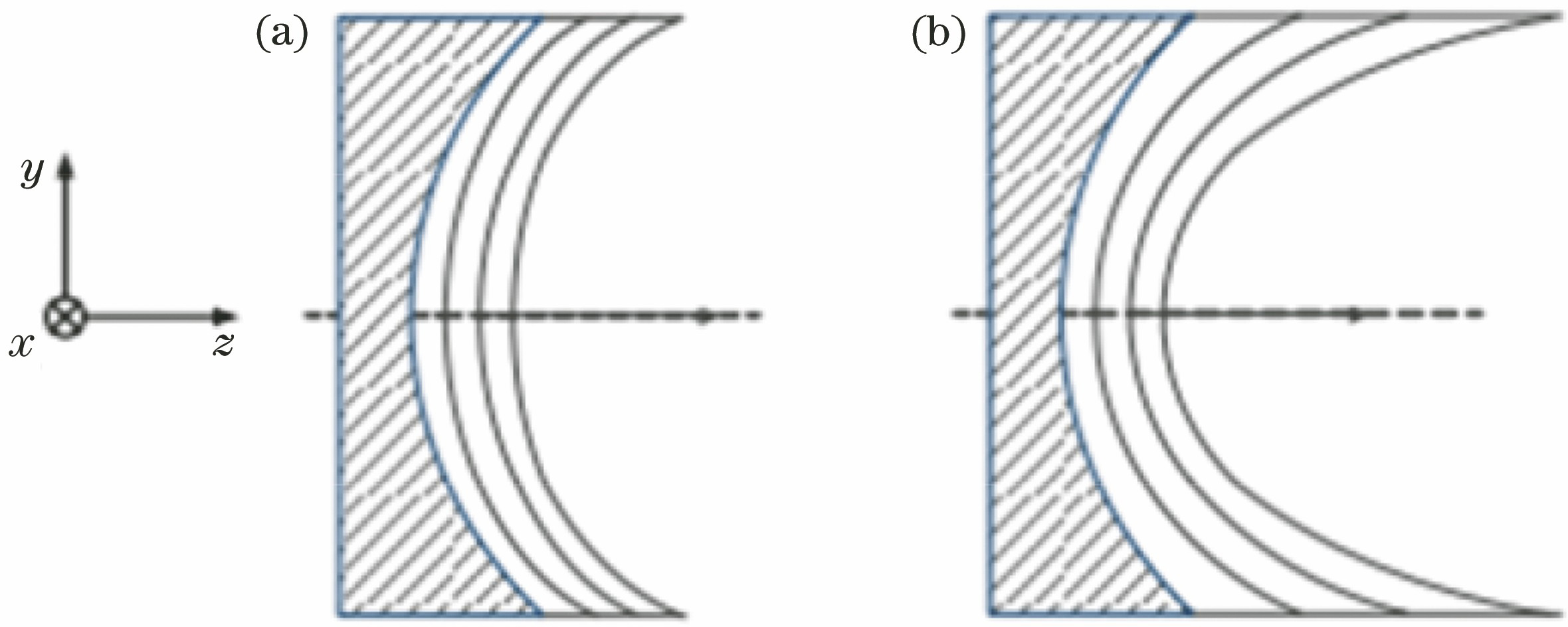
Fig. 1. Thickness distribution of multilayer films. (a) Regular multilayer films; (b) laterally graded multilayer films
![Mo/Si regular film reflectivity versus incident angle[4]](/richHtml/gxxb/2020/40/5/0522001/img_2.jpg)
Fig. 2. Mo/Si regular film reflectivity versus incident angle[4]
Fig. 3. Optical path of anamorphic magnification EUV lithography objective system in yz plane when MH=4 and ML=8
Fig. 4. Image field and field points F1--F9
Fig. 5. Flow chart of progressive optimization design for graded multilayer films
Fig. 6. Reflectivity distribution of M1, M2, M3, and M5 mirrors when single mirror is added with progressively optimized laterally graded multilayer films, and remaining mirrors are all bare mirrors (assuming ideal reflection).(a) M1; (b) M2; (c) M3; (d) M5
Fig. 7. Reflectivity distribution and wavefront aberration distribution of film-containing objective system in final multilayer film design scheme. (a) F2, reflectivity; (b) F9, reflectivity; (c) F2, wavefront aberration; (d) F9, wavefront aberration
|
Table 1. Performance indexes of anamorphic magnification EUV lithography objective system after optimization
|
Table 2. Range of incident angle and average incident angle of anamorphic magnification EUV lithography objective system with NA=0.6
| |||||||||||||||||||||||
Table 3. Minimum reflectivity distribution of M1--M6 mirrors
|
Table 4. Laterally graded multilayer film parameters of mirrors M1, M2, M3, M5
|
Table 5. Gradient variation parameters of laterally graded multilayer films with progressive optimization design
|
Table 6. Wavefront aberrations and Strehl of bare mirror system and film-containing objective system at center and edge field points

Set citation alerts for the article
Please enter your email address
© Copyright 2018-2021 | Chinese Laser Press. All Rights Reserved 沪ICP备15018463号-20