• Laser & Optoelectronics Progress
  • Vol. 61, Issue 9, 0914001 (2024)
Yingwei Zhang1、*, Jing Wang1, Quanwei Sun2, Qian Bai2, Hefeng Ling1, and Xiaodan Li1
Author Affiliations
  • 1AVIC Shenyang Aircraft Industrial (Group) Co., Ltd., Shenyang 110850, Liaoning, China
  • 2State Key Laboratory of High-Performance Precision Manufacturing, Dalian University of Technology, Dalian 116024, Liaoning, China
  • show less
    DOI: 10.3788/LOP230913 Cite this Article Set citation alerts
    Yingwei Zhang, Jing Wang, Quanwei Sun, Qian Bai, Hefeng Ling, Xiaodan Li. Process Parameters of Additive and Subtractive Hybrid Manufacturing for GH3536 Superalloy[J]. Laser & Optoelectronics Progress, 2024, 61(9): 0914001 Copy Citation Text show less
    ASHM machine
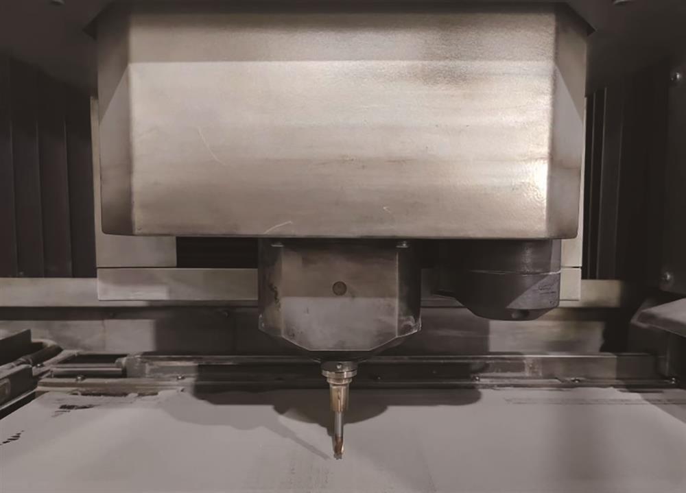
    Fig. 1. ASHM machine
    SEM and particle size distribution of GH3536 powder
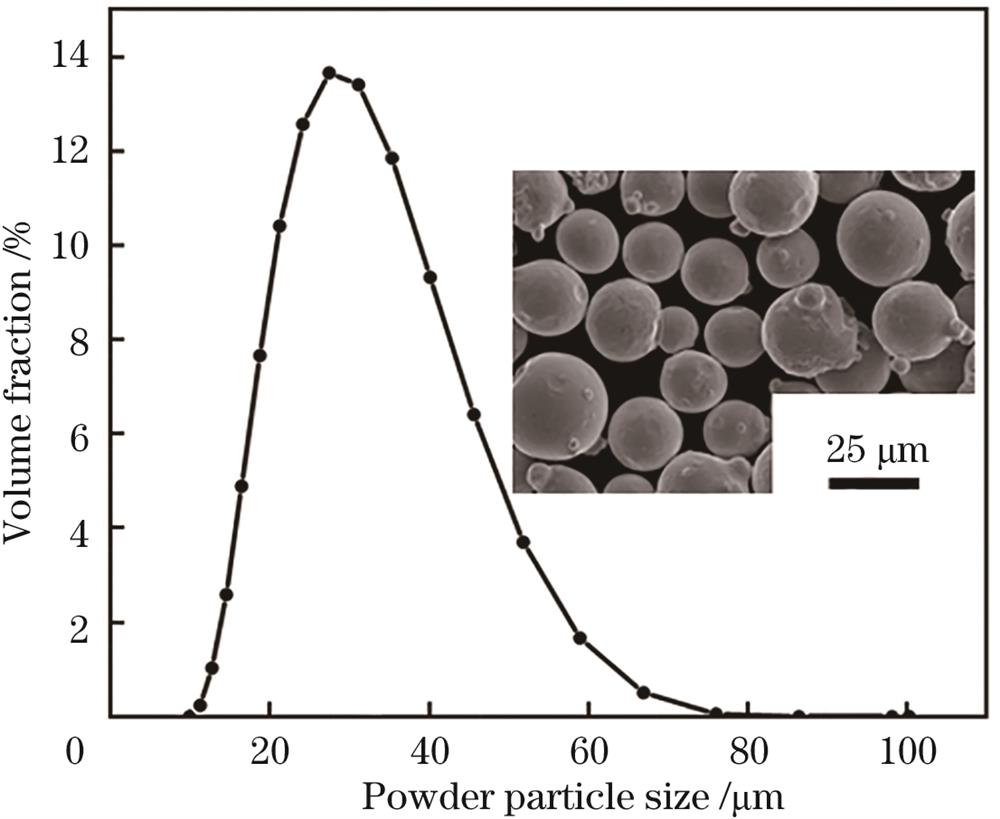
    Fig. 2. SEM and particle size distribution of GH3536 powder
    Regular relationship between laser volume energy density and relative density of GH3536 [insets (a)(b)(c) show the blowhole defects, free of all defects and spheroidization defects]
    Fig. 3. Regular relationship between laser volume energy density and relative density of GH3536 [insets (a)(b)(c) show the blowhole defects, free of all defects and spheroidization defects]
    Additive surface morphologies of GH3536 sample formed by SLM. (a)(b) SEM images of the original additive surface; (c) original additive surface morphology by white light interferometer
    Fig. 4. Additive surface morphologies of GH3536 sample formed by SLM. (a)(b) SEM images of the original additive surface; (c) original additive surface morphology by white light interferometer
    Microstructure of additive GH3536 sample formed by SLM. (a) Optical microscopic image after polishing; (b)‒(f) SEM and EBSD images of the microstructure after corrosion
    Fig. 5. Microstructure of additive GH3536 sample formed by SLM. (a) Optical microscopic image after polishing; (b)‒(f) SEM and EBSD images of the microstructure after corrosion
    Sample preparation model and tool selection scheme for GH3536 by ASHM. (a) Sample model; (b) cutting tool types
    Fig. 6. Sample preparation model and tool selection scheme for GH3536 by ASHM. (a) Sample model; (b) cutting tool types
    Schematic diagrams of milling with different types of tools and roughness of the processed sample surface. (a) Ball end milling tool, (b) round nose milling tool; (c) flat end milling tool; (d) roughness of the surface processed by ball end milling tool; (e) roughness of the surface processed by round nose milling tool; (f) broken fracture of flat end milling tool
    Fig. 7. Schematic diagrams of milling with different types of tools and roughness of the processed sample surface. (a) Ball end milling tool, (b) round nose milling tool; (c) flat end milling tool; (d) roughness of the surface processed by ball end milling tool; (e) roughness of the surface processed by round nose milling tool; (f) broken fracture of flat end milling tool
    ElementCrNiMoCoMnSiCP、SFeWAl
    Mass fraction /%22.520Bal.9.4601.6000.0300.3300.0700.00719.3600.7400.050
    Table 1. Chemical composition of GH3536 superalloy powder
    Process parameterParameter value
    Thickness of powder layer d /μm40
    Radius of laser spot r0 /μm100
    Scanning distance h /µm80
    Laser power P /W250,300,350,400,450
    Scanning speed v /(mm/s)500,750,1000,1250,1500,1750,2000
    Table 2. SLM forming process parameters of GH3536 superalloy
    SampleTool type

    Spindle speed

    n /(r/min)

    Feed rate

    f /(mm/min)

    Cutting depth

    ap /mm

    Separation distance z /mm
    T1Ball end milling2500018000.10.1
    T2Round nose milling2500018000.10.1
    T3Flat end milling2500018000.10.1
    Table 3. Milling process parameters of GH3536
    Yingwei Zhang, Jing Wang, Quanwei Sun, Qian Bai, Hefeng Ling, Xiaodan Li. Process Parameters of Additive and Subtractive Hybrid Manufacturing for GH3536 Superalloy[J]. Laser & Optoelectronics Progress, 2024, 61(9): 0914001
    Download Citation