
Junhao Zhu, Shengtong Wang, Xinghui Li. Ultraprecision Grating Positioning Technology for Wafer Stage of Lithography Machine[J]. Laser & Optoelectronics Progress, 2022, 59(9): 0922019
- Laser & Optoelectronics Progress
- Vol. 59, Issue 9, 0922019 (2022)
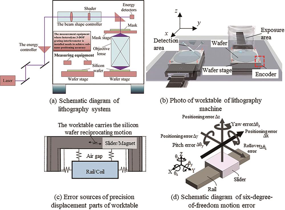
Fig. 1. Schematic diagrams of wafer stage and six-degree-of-freedom positioning in lithography machine. (a) Schematic diagram of lithography system; (b) photo of worktable of lithography machine; (c) error sources of precision displacement parts of worktable; (d) schematic diagram of six-degree-of-freedom motion error
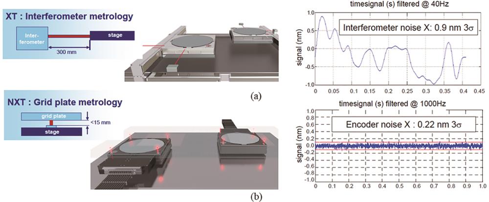
Fig. 2. Comparison of laser interferometer and grating interferometer measurement system used by ASML lithography machine in the Netherlands. (a) Laser interferometer measurement system; (b) grating interferometer measurement system
Fig. 3. Basic principle of high precision grating interferometer and sub-nano measurement scheme. (a) Principle of one dimensional diffraction grating displacement measurement; (b) Magnescale grating interferometer; (c) self-collimating grating interferometer
Fig. 4. Two-degree-of-freedom grating interferometer
Fig. 5. KGM 282 two-degree-of-freedom grating interferometer developed by Heidenhain company[37]
Fig. 6. Schematic of absolute displacement measurement
Fig. 7. XY two-degree-of-freedom grating interferometer based on two-dimensional grating
Fig. 8. XYZ three-degree-of-freedom grating interferometer with out of plane measurement capability based on two-dimensional grating. (a) Three-DOF grating interferometer; (b) three-DOF grating interferometer with self-collimating structure
Fig. 9. Heterodyne three-degree-of-freedom grating interferometer based on two gratings
Fig. 10. Heterodyne three-degree-of-freedom grating interferometer with single grating and common optical path
Fig. 11. Single-measuring-point six-degree-of-freedom measuring system
Fig. 12. Multi-measuring-point six-degree-of-freedom measuring system. (a) Three-beam six-DOF measurement system based on two-dimensional grating; (b) six-DOF measurement system based on two measuring points and three measuring units
Fig. 13. Heterodyne three measuring points and six-degree-of-freedom measuring system
Fig. 14. Illustration of large-area, high-resolution projection lithography technology
Fig. 15. Interference exposure system based on the orthogonal two-axis Lloyd’s mirror interference unit
Fig. 16. Technical route of “four gratings-four reading heads” adopted by ASML company
Fig. 17. Geometric relation calculation of multi grating multi reading head coordinate system and test of two-degree-of-freedom grating interferometer
Fig. 18. Grating profile error and periodic deviation obtained based on large-area wavefront interference and their comparison results
Fig. 19. Virtual reflection phenomenon of different Doppler shift orders
|
Table 1. Performance requirements for advanced node 14 nm lithography machine workpiece stage
|
Table 2. Performance comparison of grating interferometer

Set citation alerts for the article
Please enter your email address
© Copyright 2018-2021 | Chinese Laser Press. All Rights Reserved 沪ICP备15018463号-20