
Chenrong Gong, Lin Chen, Weihua Liu, Guohe Zhang. Study of short-term synaptic plasticity in Ion-Gel gated graphene electric-double-layer synaptic transistors[J]. Journal of Semiconductors, 2021, 42(1): 014101
- Journal of Semiconductors
- Vol. 42, Issue 1, 014101 (2021)
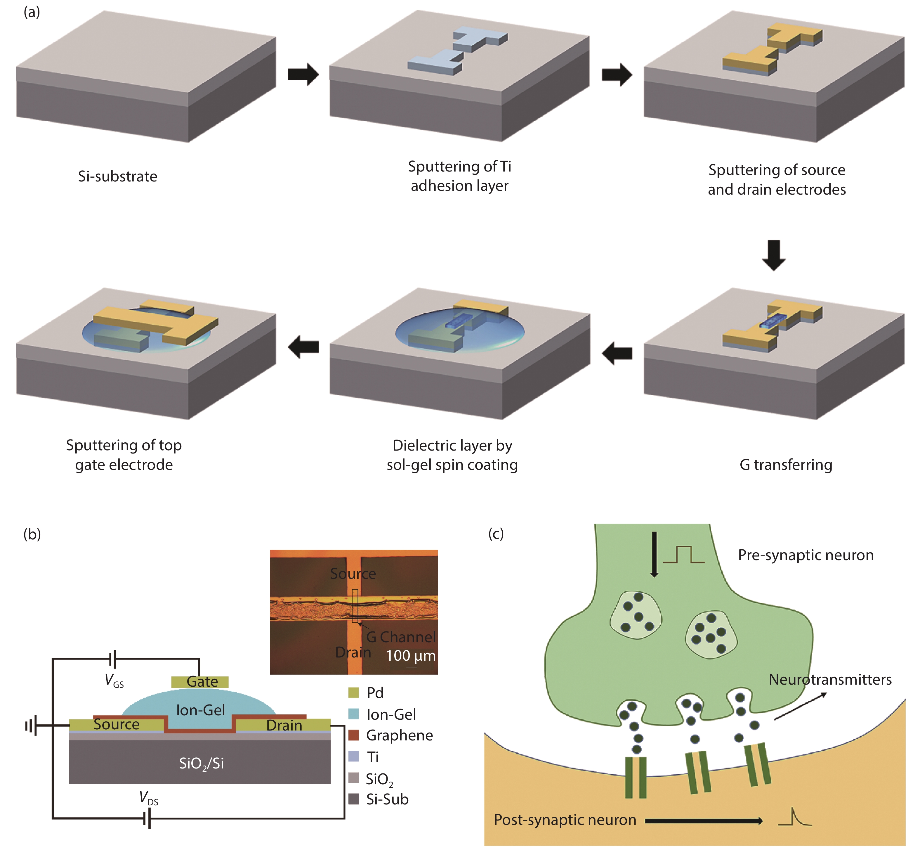
Fig. 1. (Color online) (a) An illustration of the process flow for the fabrication of graphene EDLTs. (b) Schematic and the top-view optical image of the graphene synaptic transistor. (c) Structure of the corresponding biological synapse.
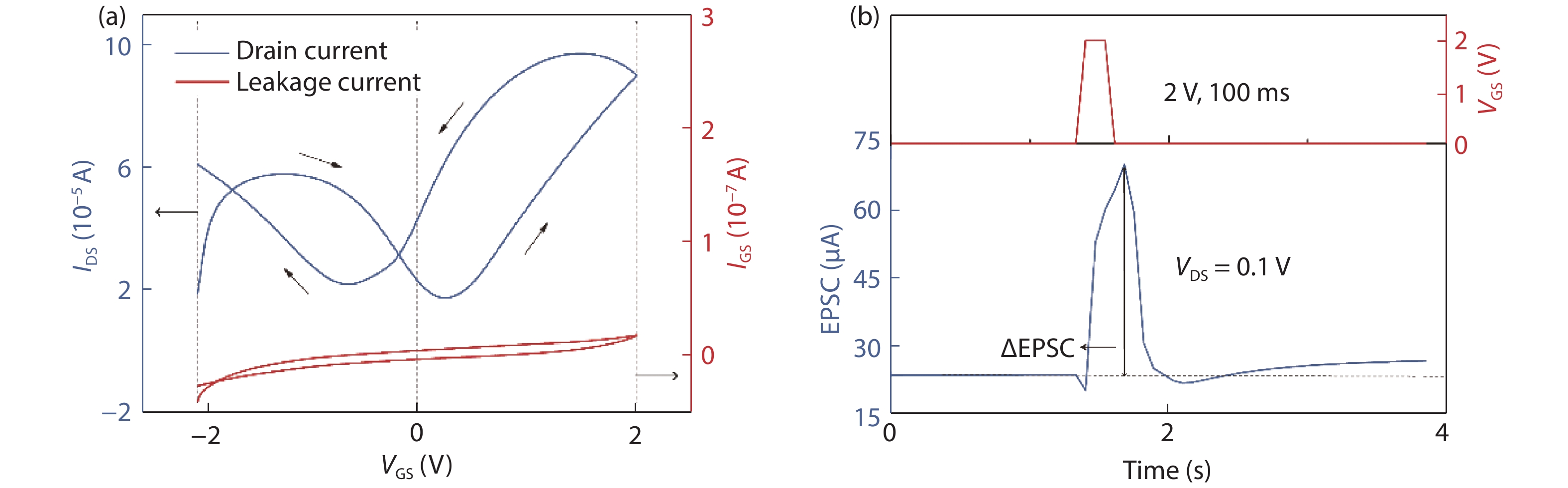
Fig. 2. (Color online) (a) Transfer curve (left) of the graphene transistor and the leakage current (right) through Ion-Gel. Fixed bias V DS = 0.1 V. (b) A presynaptic spike (top) applied on the top-gate electrode and EPSC (bottom) triggered by the spike are shown versus time.
Fig. 3. (Color online) The working mechanisms of the synaptic device under positive voltage. Charge distributions (a) before the pulse is applied, (b) when a positive voltage is just applied, (c) after applied spike stabilization, (d) when the spike is just removed, and (e) after removing the pulse for a while are shown respectively. (f) Drain current corresponding to the mechanism.
Fig. 4. (Color online) (a) EPSCs triggered by different spike duration for the same spike amplitude of 2 V are shown versus time. The spike duration increases from 100 to 600 ms. Inset: ΔEPSCs versus spike duration are plotted. (b) EPSCs triggered by different spike amplitude for the same spike duration of 100 ms are shown versus time. The spike amplitude increases from 0.5 to 3 V. Inset: ΔEPSCs versus spike amplitude are plotted.
Fig. 5. (Color online) (a) A paired presynaptic spikes (2 V, 100 ms) with ΔT of 300 ms (top) applied on the transistor and the typical EPSC curve (bottom) triggered by the spikes are shown. (b) PPF index versus ΔT is plotted. The experimental data are fitted using a double exponential function.

Set citation alerts for the article
Please enter your email address
© Copyright 2018-2021 | Chinese Laser Press. All Rights Reserved 沪ICP备15018463号-20