• Photonics Research
  • Vol. 9, Issue 12, 2501 (2021)
Chen Bai1、†, Tong Peng1、2、†, Junwei Min1, Runze Li1, Yuan Zhou1, and Baoli Yao1、3、*
Author Affiliations
  • 1State Key Laboratory of Transient Optics and Photonics, Xi’an Institute of Optics and Precision Mechanics, Chinese Academy of Sciences, Xi’an 710119, China
  • 2Xi’an Jiaotong University, Xi’an 710049, China
  • 3Pilot National Laboratory for Marine Science and Technology (Qingdao), Qingdao 266200, China
  • show less
    DOI: 10.1364/PRJ.441054 Cite this Article Set citation alerts
    Chen Bai, Tong Peng, Junwei Min, Runze Li, Yuan Zhou, Baoli Yao. Dual-wavelength in-line digital holography with untrained deep neural networks[J]. Photonics Research, 2021, 9(12): 2501 Copy Citation Text show less

    Abstract

    Dual-wavelength in-line digital holography (DIDH) is one of the popular methods for quantitative phase imaging of objects with non-contact and high-accuracy features. Two technical challenges in the reconstruction of these objects include suppressing the amplified noise and the twin-image that respectively originate from the phase difference and the phase-conjugated wavefronts. In contrast to the conventional methods, the deep learning network has become a powerful tool for estimating phase information in DIDH with the assistance of noise suppressing or twin-image removing ability. However, most of the current deep learning-based methods rely on supervised learning and training instances, thereby resulting in weakness when it comes to applying this training to practical imaging settings. In this paper, a new DIDH network (DIDH-Net) is proposed, which encapsulates the prior image information and the physical imaging process in an untrained deep neural network. The DIDH-Net can effectively suppress the amplified noise and the twin-image of the DIDH simultaneously by automatically adjusting the weights of the network. The obtained results demonstrate that the proposed method with robust phase reconstruction is well suited to improve the imaging performance of DIDH.

    1. INTRODUCTION

    Digital holography (DH) can “capture and freeze” the wavefront of an object wave and realize lensless imaging based on interference [1]. The ability to recover phases makes DH widely used in biomedicine and materials science as a means of quantitative phase imaging [2]. Typically, DH employs two major configurations: in-line and off-axis structures [3]. Even though the off-axis technique allows wavefront reconstruction from a single-shot digital hologram, space bandwidth and resolution losses are frequently introduced [4,5]. In comparison, in-line DH, with its relatively simple and compact setup, is often preferred in many microscopic imaging techniques [5]. However, the original phase map reconstructed by DH, in both the off-axis and in-line approaches, is often limited by 2π phase wrapping [6]. This phase wrapping can be subsided by using unwrapping algorithms [7]. However, outstanding performances are hardly achieved due to the influences that are easily caused by many factors. Moreover, such algorithms often fail to measure samples that have a high-aspect-ratio or a rough surface [8].

    Compared with single-wavelength DH, recording holograms with dual-wavelengths is another effective method to quantitatively retrieve unwrapped phase information of samples [9,10]. Dual-wavelength in-line digital holography (DIDH) not only expands the range of the measured optical path difference (OPD) by a synthesized beat wavelength but also achieves high-resolution measurement and fast implementation [10]. Unfortunately, two inherent factors often obfuscate the reconstruction in practical DIDH: (1) the noise signals at each wavelength detection appear in the dual-wavelength hologram at the same time, leading to amplified noise in the phase reconstruction [11], and (2) the well-known twin-image problem that manifests itself as an out-of-focus version of the reconstructed plane should be bounded to in-line DH [5].

    To reduce the phase noise and increase the reconstructed accuracy in DH, numerical filtering, a headmost approach, can be easily implemented to remove noises, but the details of the object itself are also often filtered out [12]. Additionally, the phase distribution with suppressed noise can be directly acquired via the linear regression [13], although it is common for the determination of parameters to hardly satisfy the imaging relationship. In contrast, the level of the amplified noise can be reduced to the order of a single wavelength by introducing the guiding phase [11]. In terms of the twin-image problem, existent solutions can be mainly classified into two strategies, i.e., the physical modification in a holographic setup [14] and the numerical compensation [5,6]. Even though some specific setups have been proven to get rid of the twin-image, the complexity of the DH setup is often unavoidably increased. In contrast, numerical solutions, known as phase retrieval [15], are essentially a class of iterative algorithms that reduce the twin-image and acquire a relatively real phase at each iteration, such as the finite transmission constraint [16] and the Gerchberg–Saxton (GS) algorithm [17]. Moreover, based on Fourier analysis and sparsity, the wave propagation is physically modeled with compressive sensing (CS), which leads to a physics-driven compressive sensing-digital holography (CS-DH) method [18], taking advantage of the significant difference between the twin-image and the existing object. However, most of these traditional frameworks often struggle in the presence of strong noise [19], which becomes more notable when encountering amplified noise in DIDH.

    Recently, deep learning (DL) has been successfully utilized for phase retrieval from only one intensity pattern [4], which also converts reconstructions to artifacts-free [20], twin-image-free [21], or noise-free [22] versions. As a powerful machine learning method, DL should be naturally introduced in DIDH. However, most DL-based strategies are data-driven or end-to-end net approaches [22], including derivatives like the regularization by denoising (RED) frame [23], which results in excessive data dependency and limited generalization ability, especially when the reconstructed target is out of the training set [23]. In contrast, an untrained network, as a training-free DL approach, has been investigated to directly reconstruct high-quality image or phase information through self-calibration, typically via a deep image prior (DIP) framework [24,25] or by coupling double DIPs with more decomposed basic components [26]. In these paradigms, a complete physical model that represents the imaging process and the DIP frame can be combined for more practical interpretability [24]. Even though single-wavelength twin-image-free DH has been implemented with DIP, called deep DIH [27], artifacts are caused when measuring phases with relatively strong noises due to the lack of special treatments, thereby hardly transferring to the DIDH directly as the distortions of the phase should be further deteriorated due to the amplified noise. In contrast, concise deep decoder (CDD), as a variant of DIP, provides a much simpler and under parameterized architecture to learn a low-dimensional manifold and a decoding operation of the full image, which can be a relatively more robust and faster convergent than DIP [28]. However, the CDD has hitherto not been incorporated into a complete physical model with practical imaging interpretability.

    Enlightened by previous studies, this work demonstrates that it is possible to experimentally recover the phase distribution of a sample with suppressed twin-image and noise from DIDH via untrained neural networks, i.e., DIDH-Net, which is built by combining concise and non-convolutional networks [28] with a real-world imaging model. In terms of DIDH-Net, the incorporation of CDD with a task-specific DIDH model for optical imaging reduces the amount of labeled data required to train the network. Thus, neither additional modification of the setup nor operations (for example, phase shifting, training data) are required, which enables a high-resolution and high-accuracy measurement.

    2. METHODS

    A. Problem Statement

    Suppose that a sample with a certain optical thickness L is illuminated simultaneously by two different wavelengths of λ1 and λ2 without color absorption. In most cases, L is larger than λ1 and λ2, and thus the corresponding phase diagram Φestm (m=1,2), estimated from the captured hologram Icapm, can be written as follows: Φestm=Φpurem+2πεm=φm+2πcm+2πεm,where Φpurem is the noise-free phase, φ1 and φ2 are the unwrapped phases at each single-wavelength and belong to [0,2π], c1 and c2 are unknown nonnegative integers at a certain point (x,y) of the wrapped phase image, and 2πεm represents the variance of noise that was introduced by the detection noise into the phase estimation. For the DIDH technique, the optical thickness of sample L can be calculated as follows [6,13]: L={ΛΦest1(x,y)Φest2(x,y)2π,Φest1(x,y)Φest2(x,y)0,ΛΦest1(x,y)Φest2(x,y)+2π2π,Φest1(x,y)Φest2(x,y)<0,where Λ=λ1λ2/|λ1λ2| is the beat wavelength [6]. Moreover, due to the high wavelength selectivity of the Bayer mosaic filter of the color camera, two single-wavelength holograms, Icap1 and Icap2, can be extracted from the single-shot dual-wavelength hologram IcapRGB for subsequent processing without the crosstalk between the two wavelengths [6,29] as follows: [Icap1Icap2]=[a1r2+a1g2+a1b2a1ra2r+a1ga2g+a1ba2ba1ra2r+a1ga2g+a1ba2ba2r2+a2g2+a2b2]1[a1rIcapHR+a1gIcapHG+a1bIcapHBa2rIcapHR+a2gIcapHG+a2bIcapHB],where (IcapHR,IcapHG,IcapHB) are the red, green, and blue (RGB) components of the recorded color hologram IcapRGB, and (a1r,a1g,a1b) and (a2r,a2g,a2b) are the RGB components of the single-wavelength hologram at λ1 and λ2, respectively, which can be calibrated with the corresponding single-wavelength imaging at the beginning of the experiment.

    1. Amplified Noise Obstructs the High-Precision Reconstruction

    According to Eqs. (1) and (2), the optical thickness L can also be expressed as follows: L={ΛΦpure1(x,y)Φpure2(x,y)2π+Λ(ε1+ε2),Φpure1(x,y)Φpure2(x,y)0,ΛΦpure1(x,y)Φpure2(x,y)+2π2π+Λ(ε1+ε2),Φpure1(x,y)Φpure2(x,y)<0.

    In other words, the amplitude of the noise contained in the single-wavelength phase wrapping diagram φm(x,y) is 2πεm, and the corresponding noise in the optical path change Lm(x,y) is λmεm. In the phase difference distribution φ1(x,y)φ2(x,y), i.e., the noise level is 2π(ε1+ε2), and the corresponding noise in the finally reconstructed optical thickness L is Λ(ε1+ε2). Compared with the single wave length, the noise increases by Λ(ε1+ε2)/λmεm, which approximately reaches 2Λ/λm, thereby amplifying the noise in the phase distribution and the reconstructed thickness. A smaller beat wavelength can weaken the problem of amplified noise, but its range in measurement is limited. Thus, the amplified noise can be suppressed under the condition of a large beat wavelength by eliminating the noise at each wavelength.

    2. Twin-Image Problem Caused by Interference

    To illustrate the twin-image problem of DIDH, Uobjm is used as an object wave in terms of the m-th wavelength, and the non-scattered wave Rrefm is used as the reference wave. Subsequently, the hologram Icapm exists simultaneously in the interference of the physical symmetry [18] as follows: Icapm=HDIDHm{Φpurem}+Ecapm=|Uobjm+Rrefm|2+Ecapm=[Uobjm]*Rrefm+Uobjm[Rrefm]*+|Uobjm|2+|Rrefm|2+Ecapm,where HDIDHm{·} means the forward operator or mapping function, Ecapm is the detection noise, and * represents the conjugate term. Even though the original intention of DH is to record the wavefront Uobjm, the physical conjugate terms [Uobjm]*Rrefm and Uobjm[Rrefm]* are recorded together, and the conjugate wave [Uobjm]* is also recorded as a by-product. As a result, the reconstruction of the virtual image plane is the superposition of the original object and the twin-image. This is usually because the reconstruction of holograms is considered to be a wave rather than a transmission reconstruction problem.

    B. Untrained Network-Based DIDH Reconstruction

    Since DIDH only depends on intensity measurement, the reconstruction can be regarded as a highly ill-conditioned inverse problem. The DIDH-Net method proposed here only needs one captured intensity hologram, IcapRGB(z=d), which specifically means a diffraction DH pattern formed at the distance of d from the imaging plane located at z=0. As shown in Fig. 1, after extracting holograms [Icap1(z=d),Icap2(z=d)] at each wavelength from the single-shot dual-wavelength hologram IcapRGB(z=d) used in Eq. (3), the diffractive DH pattern Icapm(z=d) is then input to the designed structure for generating the estimated phase of the object Φest(z=0). In a traditional neural network, it is necessary to know the true phase object Φpure(z=0) in the training set and calculate the error between Φest(z=0) and Φpure(z=0) to optimize the weight and deviation. However, the proposed DIDH-Net does not require the true phase Φpure(z=0). Instead, the physical model HDIDHm,z{·}, a specific mapping process in Eq. (5), is utilized to calculate Φest(z=0) from Iestm(z=d). Then the weight and bias of the net are optimized by the error between Iestm(z=d) and the measured Icapm(z=d) with gradient descent. In other words, the estimated diffraction hologram Iestm(z=d) is forced to gradually converge to the measurement hologram Icapm(z=d), which continues as an iterative process, as shown in Fig. 1. Finally, the phase search can converge to a feasible solution after the whole iterative process, subsequently reconstructing the optical thickness distribution L.

    Schematic of the DIDH-Net imaging system. A captured hologram IcapRGB(z=d) of a phase object is the input to the neural networks after extracting holograms at each wavelength. The output of the neural networks is taken as the estimated phase Φestm(z=0), which is then numerically propagated to simulate the diffraction and measurement processes HDIDHm,z{·} to generate Iestm(z=d). The mean square errors (MSEs) between Icapm(z=d) and Iestm(z=d) are measured as the loss value to adjust the neural network parameters. The optical thickness distribution L can finally be acquired with the suppressed amplified noises and the free twin-image.

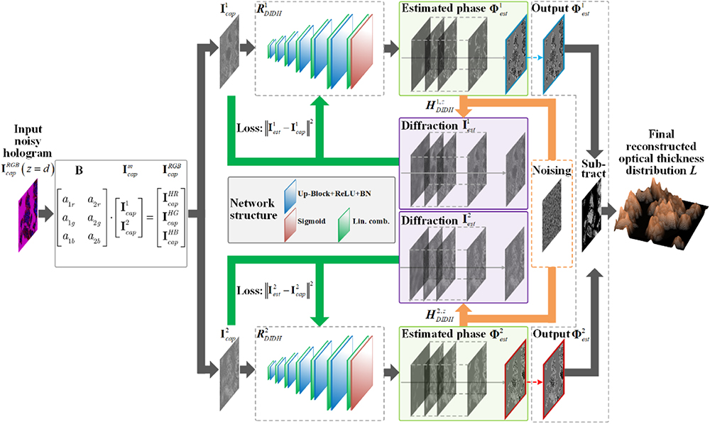
    Figure 1.Schematic of the DIDH-Net imaging system. A captured hologram IcapRGB(z=d) of a phase object is the input to the neural networks after extracting holograms at each wavelength. The output of the neural networks is taken as the estimated phase Φestm(z=0), which is then numerically propagated to simulate the diffraction and measurement processes HDIDHm,z{·} to generate Iestm(z=d). The mean square errors (MSEs) between Icapm(z=d) and Iestm(z=d) are measured as the loss value to adjust the neural network parameters. The optical thickness distribution L can finally be acquired with the suppressed amplified noises and the free twin-image.

    Specifically, as a phase object Φpure(z=0) is illuminated by dual-wavelength coherent plane waves, the diffraction pattern Uobjm(z=d) with a propagation distance z=d can be expressed as follows: Uobjm(z=d)=[Uobjm(z=0)]FFm,zexp[i2π(fxx+fyy)]dfxdfy=Gm,z[Φpurem(z=0)],where Fm,z=exp[ikz1(λmfx)2(λmfy)2] is the transfer function, [Uobjm(z=0)]F is the 2D Fourier transform of Uobjm(z=0)=Aexp[iΦpurem(z=0)], A is the amplitude that can be normalized in the subsequent process, fx and fy are the spatial frequencies, and Gm,z[·] is a transform operator expressing from Φpurem(z=0) to Uobjm(z=d). As mentioned before, the sensor not only records Uobjm(z=d) but also records its conjugation, [Uobjm(z=d)]*. According to Eq. (5), note that the term |Rrefm(z=d)|2 is simply a constant, and hence the effect of |Rrefm(z=d)|2 can be removed by eliminating the DC term. Also, the term |Uobjm(z=d)|2 can be regarded as the noise term Ecapm(z=d). In addition, Rrefm(z=d) can be assumed as one without loss of generality [30,31]. Then, the complete mapping from the object phase to the hologram can be expressed as follows: Icapm(z=d)2Re{Uobjm(z=d)}+Ecapm(z=d)=2Re{Gm,z[Φpurem(z=0)]}+Ecapm(z=d)=HDIDHm,z{Φpurem(z=0)}.

    It should be noted that HDIDHm,z{·} not only includes the physical imaging procedure of the generated diffraction pattern but also encapsulates and emphasizes the noising process in the imaging. Then, the typical method for phase imaging, which is a highly ill-posed problem, is to solve the minimization problem as follows: Φestm(z=0)=argminΦHDIDHm,z{Φpurem(z=0)}Icapm(z=d)22+r[Φpurem(z=0)],where a priori term r[·] is designed artificially or has the characteristics of a dictionary, which can capture the general regularity of objects Φestm(z=0). The idea of the optimization of Eq. (8) is the core in most of the numerical approaches of the phase retrieval.

    In contrast, a typical DL-based approach, i.e., end-to-end net [4,20,21], tries to extract a large number Q of the labeled data [Φpurem(z=0),Icapm(z=d)], q=1,2,, and Q for each wavelength m=1,2, that come from the corresponding training set STm={[Φpurem(z=0),Icapm(z=d)],m=1,2,q=1,2,,Q} to learn the mapping function of the neural network Rtypm, which can be expressed as follows: Rtypm=argminθΘRtypm[Icapm(z=d)]Φpurem(z=0)2,  [Φpurem,Icapm]STm.

    Here, Rtypm is defined by a set of weights and deviations θΘ. The training process produces a feasible mapping function Rtypm, which can map the diffraction hologram Icapm(z=d) that is not in the STm back to the corresponding phase, i.e., Φestm(z=0)=Rtypm[Icapm(z=d)]. In a typical DL application, the size Q of the training set STm can be thousands or even larger. It is experimentally time-consuming to collect such a large group of diffraction holograms Icapm(z=d) and their corresponding original phases Φpurem(z=0). This usually requires maintaining mechanical and environmental stability in the process of data acquisition for several hours. Although the training set can be created by numerical modeling of the imaging physical process, the mapping function learned in this case is only applicable to those similar test images in the training set. Only the object set with the same priority used in the training process can obtain a good generalization effect [24].

    On the contrary, in the proposed DIDH-Net model, the phase recovery formula is as follows: RDIDHm=argminθΘHDIDHm,z{RDIDHm[Icapm(z=d)]}Icapm(z=d)2.

    In this objective function, there is no real phase on the ground, which means that the DIDH-Net does not need to be trained in the basic truth stage. The interaction between HDIDHm,z{·} and RDIDHm makes the artificial neural network capture the prior information of Icapm(z=d). After optimization, the phase can be reconstructed using the obtained mapping function RDIDHm as follows: Φestm(z=0)=RDIDHm[Icapm(z=d)].

    It should be noted that there is no limit to the network architecture that can choose to implement RDIDHm. In this study, CDD was used, which only consists of a simple combination of a few building blocks, thereby achieving a relatively outstanding performance. Typically, the network structure includes an input with a diffraction hologram and a decoder path outputting a predicted phase pattern. Specifically, five main modules were used to connect the input and the output [28]: batch normalization (BN), rectified linear unit (ReLU) nonlinearity, up block, sigmoid, and the pixel-wise linear combination of channels, respectively. The neural network is based on the platform of PyTorch 1.8.0, and it was implemented with Python 3.7.6. An Adam optimizer was used with a learning rate of 0.01 to optimize the weight. In our study, the size of the input image IcapRGB(z=d) was 512×512  pixels. The network usually required 7000 periods to find a very good estimation in less than 10 min on a computer with an Intel Xeon CPU e5-2696 V3 processor with 256 GB of RAM and a double NVIDIA Titan V GPUs.

    3. RESULTS AND DISCUSSION

    A. Evaluation with the Simulated Test Dataset

    Simulations were first performed to compare the performance of the proposed DIDH-Net with the backpropagation (BP), CS-DH, end-to-end net, deep DIH, and RED frameworks. A phase object, 512×512  pixels in size, was used in the transmission, which is shown in Fig. 2(a). The simulated illumination wavelengths were λ1=647  nm and λ2=485  nm. The maximum value of L was set to be 1.6 μm, which was a little smaller than the beat wavelength of 1.94 μm but much larger than each illumination wavelength. The distance z=d between the image plane and the image sensor was set to 10 mm to generate a pure noise-free diffraction hologram IpureRGB(z=d). The pixel size was set to 5.5 μm. Since the model mismatch and the shot noise are the main sources of noise in many phase retrieval applications, the robustness of several frameworks was evaluated with the noise process [32] as follows: IcapRGB(z=d)=IpureRGB(z=d)+EcapRGB(z=d)=ξZ+B,where Z[IpureRGB(z=d)/ξ] follows a Poisson distribution, and BN(0,σ2) follows a Gaussian distribution, which is the dominant noise with a noise level of σ2. The simulated single-shot DIDH hologram IcapRGB(z=d) is shown in Fig. 2(b), with σ=0.30 and ξ=0.02. Figures 2(c) and 2(d) show the extracted single-wavelength holograms Icap1(z=d) and Icap2(z=d) at λ1 and λ2, respectively.

    Simulation results of the numerical phase target for the single-shot DIDH. (a) The simulated optical thickness distribution of the object. (b) The simulated single-shot recorded dual-wavelength in-line hologram calculated at z=10 mm. (c) and (d) are the extracted single-wavelength holograms from (b). The white scale bar measures 200 μm.

    Figure 2.Simulation results of the numerical phase target for the single-shot DIDH. (a) The simulated optical thickness distribution of the object. (b) The simulated single-shot recorded dual-wavelength in-line hologram calculated at z=10  mm. (c) and (d) are the extracted single-wavelength holograms from (b). The white scale bar measures 200 μm.

    Comparison of the different phase retrieval methods (from left column to right column): the ground-truth images for intuitive comparison, the phase maps reconstructed by means of direct reconstruction via backpropagation, the CS-DH method, the end-to-end net with the pre-trained network, the deep DIH, the RED frame, and the DIDH-Net. The cross-section optical thickness profiles (along the red line) of each optical thickness map were also measured and are shown in the last row.

    Figure 3.Comparison of the different phase retrieval methods (from left column to right column): the ground-truth images for intuitive comparison, the phase maps reconstructed by means of direct reconstruction via backpropagation, the CS-DH method, the end-to-end net with the pre-trained network, the deep DIH, the RED frame, and the DIDH-Net. The cross-section optical thickness profiles (along the red line) of each optical thickness map were also measured and are shown in the last row.

    Additionally, the effect of the diffraction distance z on the quality of the reconstructed image was also numerically analyzed. Four diffraction distances z=1, 10, 25, and 50 mm were selected as examples to test their properties, where the maximum value of L was set to 1.6 μm. The results are shown in Fig. 4. As shown, in all cases, the DIDH-Net successfully reconstructed the phase from the corresponding diffractive DH pattern. Compared with the true value phase image in Fig. 4(f), the SSIM values of the reconstructed optical thickness distributions from Figs. 4(a)–4(d) were 0.92, 0.91, 0.90, and 0.88, respectively. This observation is also consistent with the convergence of mean square errors (MSEs), which gradually decreased in all the cases as the number of epochs increased in Fig. 4(e). Even though this simulation demonstrated that the DIDH-Net could accurately reconstruct the phase and optical thickness information of samples despite different diffraction distances, the distance between the target and the image sensor should be adjusted by considering the adequacy of the diffraction patterns and the image size acquired by the imaging sensor.

    Effect of the diffraction distance z on the quality of the reconstructed image. The diffraction holograms [top row (a1)–(d1)] were calculated at z values of 1 mm, 10 mm, 25 mm, and 50 mm, each of which followed their DIDH-Net reconstructed single-wavelength phase images and optical thickness maps in the corresponding rows. The ground truths of images are listed [far right column (f1)–(f3)] under the evolution of the MSE with an increasing number of epochs [top right corner (e)]. The scale bar measures 200 μm.

    Figure 4.Effect of the diffraction distance z on the quality of the reconstructed image. The diffraction holograms [top row (a1)–(d1)] were calculated at z values of 1 mm, 10 mm, 25 mm, and 50 mm, each of which followed their DIDH-Net reconstructed single-wavelength phase images and optical thickness maps in the corresponding rows. The ground truths of images are listed [far right column (f1)–(f3)] under the evolution of the MSE with an increasing number of epochs [top right corner (e)]. The scale bar measures 200 μm.

    The captured hologram can be noisy due to the real recording procedure. Consequently, the performance of the DIDH-Net under different noise conditions was investigated. Specifically, the diffraction hologram at z=10  mm with noise levels σ of 0.22, 0.30, and 0.38, respectively, is shown in Fig. 5. The optical thickness maps could be successfully reconstructed from the corresponding holograms by the proposed method, despite the large noises slightly decreasing the imaging quality.

    Reconstructions for the different noise levels: (a1) and (a2) the noise-free hologram at z=10 mm. The DIDH-Net reconstructed optical thickness maps along with the corresponding results with noise levels of (b1) and (b2) σ=0.22, (c1) and (c2) σ=0.30, and (d1) and (d2) σ=0.38. The PSNRs and SSIMs of the optical thickness maps computed against the noise-free ones were also evaluated. The scale bar measures 200 μm.

    Figure 5.Reconstructions for the different noise levels: (a1) and (a2) the noise-free hologram at z=10  mm. The DIDH-Net reconstructed optical thickness maps along with the corresponding results with noise levels of (b1) and (b2) σ=0.22, (c1) and (c2) σ=0.30, and (d1) and (d2) σ=0.38. The PSNRs and SSIMs of the optical thickness maps computed against the noise-free ones were also evaluated. The scale bar measures 200 μm.

    B. Experimental Results of Different Samples

    1. Experimental Setup

    Experiments were carried out to verify the effectiveness and feasibility of the proposed method in practice, and the experimental setup is shown in Fig. 6. Two semiconductor lasers with wavelengths of λ1=647  nm and λ2=485  nm (OBIS, Coherent, Inc., USA) were used as illumination sources. The two laser beams were combined by the dichroic mirror (DM, Thorlabs Inc., USA) before passing through a reversed telescope (L1, f=50  mm and L2, f=150  mm) for beam expansion. After passing through a polarizer (P, Thorlabs Inc., USA) to ensure consistent polarization and through the non-polarizing cube beam splitter 1 (NPBS1, Thorlabs Inc., USA), the beams were split into object waves and reference waves, respectively. The collinear object waves illuminated the specimen, and the transmitted waves were collected by the objective (20×/NA0.55, Nikon Inc., Japan) that was aligned in a 4f configuration with tube lens L4 (f=200  mm) to image the sample onto the image plane. To ensure the equal optical path, the reference waves passed through an identical objective (20×/NA0.55, Nikon Inc., Japan) and tube lens L3 (f=200  mm). The thickness of the specimens was smaller than the beat wavelength but larger than each illumination wavelength. The object wave and reference wave interfered after the NPBS2, and the dual-wavelength in-line hologram was recorded by a color CMOS camera (UI-3370CP-C-HQ, 2048×2048  pixels and 5.5 μm pixel size, IDS GmbH, Germany). At first, the CMOS camera was fixed on a moving stage (travel range of 25 mm, displacement accuracy of 0.05 μm, KMTS25E/M, Thorlabs, USA) and placed in the image plane to make sure the target was in focus. Then, the CMOS camera was controlled by the moving stage to translate along the z axis. With an accurate and achievable movement, the actual propagating distance could be acquired with high precision. Ultimately, the phase was reconstructed from the diffraction hologram recorded at a distance from the image plane, where the imaging distance z was empirically set to 10 mm by considering the data adequacy and pixel size of the imaging sensor. Additionally, the optical system used the achromatic lenses to eliminate the chromatic aberration.

    Schematic of the experimental setup of the DIDH.

    Figure 6.Schematic of the experimental setup of the DIDH.

    2. Imaging Results with Different Samples

    First, a 180-nm-thick rectangular phase step was selected for the imaging experiment, and the dual-wavelength diffraction hologram was recorded and is shown in Fig. 7(a). The proposed DIDH-Net took the diffraction hologram as its only input and generated the output phase diagram, where the noise level could also be estimated accurately [36]. Compared with the other methods, an envelope curve representing the optical thickness was smoother and in line with the actual situation, which shows the advantages of the proposed method in suppressing the twin-image and the expanding noise again. The average optical thickness, calculated according to the envelope curve, was 180.13 nm, which matched the actual value well. Furthermore, a micro-lens with a spherical top optical thickness of 800 nm was also tested and is shown in Fig. 7(b). Like the phase step results, both the phase image and the corresponding optical thickness curve of the DIDH-Net showed the best reconstruction. Among these methods, the robustness of the CS method in practical application was not good, which also verifies that the convergence of the algorithm was greatly affected in the presence of strong interference. Moreover, the measured results were almost in agreement with the nominal values, which convincingly proves that the proposed method could directly reconstruct the quantitative optical thickness distribution of the specimen from one single-shot dual-wavelength in-line hologram at a high accuracy.

    Experimental images of the rectangular phase-step [top row (a1)–(e1)] and micro-lens [second row (a2)–(e2)] processed with the backpropagation, the CS, the RED, and the DIDH-Net methods, respectively. The cross-section optical thickness profiles (along the dashed line) were also measured in insets. The scale bars measure 30 μm.

    Figure 7.Experimental images of the rectangular phase-step [top row (a1)–(e1)] and micro-lens [second row (a2)–(e2)] processed with the backpropagation, the CS, the RED, and the DIDH-Net methods, respectively. The cross-section optical thickness profiles (along the dashed line) were also measured in insets. The scale bars measure 30 μm.

    Furthermore, imaging experiments on biological specimens (Ascaris eggs and a water flea jumping foot) were also performed, where the corresponding three-dimensional optical thicknesses based on the reconstructed phase information were simultaneously calculated. Specifically, the plane wave was guided to illuminate the samples, which also produced intensity images of a bright field, as shown in Figs. 8(a1) and 8(b1). Only the images illuminated by a single wavelength are shown for better understanding and comparison with the phase results. To acquire the diffraction hologram, the camera was placed at a distance z=10  mm from the image plane. After that, the phase results were reconstructed using different methods, which are shown in Figs. 8(a3)–8(a6) and 8(b3)–8(b6). Moreover, as the ground truth was unavailable, a no-reference perceptual blur metric (NPBM [37]), spanning from 0 to 1 (lower was better) was introduced to evaluate the results. Similarly, due to the influence of the twin-images, there were many artifacts in the backpropagation method, and the averaged NPBM was 0.58. By using the CS regularization constraint, the twin-images and the expanded noise were suppressed to a certain extent, in which the averaged NPBM reached 0.41, but the signal-to-noise ratio was still low. In contrast, the traditional RED method could obtain relatively satisfactory results in terms of the reconstructed phase and optical thickness information, but a small amount of information was lost after optical thickness information reconstruction, which is reflected in the averaged NPBM of 0.34. The DIDH-Net method was more accurate in the presence of the twin-image and the amplified noise, and it showed good robustness and the best-averaged NPBM of 0.30. It should be noted that all experiments removed the additional phase brought by the transparent substrate or coverslips. Specifically, a hologram of the specimen-free area, which includes the substrate or the substrate and the coverslips, was recorded at the beginning of each experiment to retrieve a specimen-free phase map that was subtracted from the reconstructed phase distributions with the specimen, i.e., the phase subtraction with double exposure [38] was implemented. In addition, the DIDH-Net requires precise modeling of the image formation mechanism, i.e., HDIDHm,z{·} in our study, which means that the more accurate the measurements, the better the reconstruction results. In order to overcome the effects of the slightly imperfect measurements to achieve the accurate reconstruction, such as phase aberrations caused by nonideal beam collimation and propagating distance measurement, double-exposure [38], mentioned above, and auto-focusing [39] could be respectively utilized, thereby bringing some benefits in imaging, whereas this is not the focus of current study.

    Imaging results of (a) Ascaris eggs and (b) water flea jumping foot by different methods, including the final reconstructed phase maps and their corresponding optical thickness maps.

    Figure 8.Imaging results of (a) Ascaris eggs and (b) water flea jumping foot by different methods, including the final reconstructed phase maps and their corresponding optical thickness maps.

    Compared with the other numerous approaches (based on GS, CS, and so on) that often make a trade-off between accurate phase reconstructions and robustness, the DL-based methods have several advantages in the phase measure of holography [21,40]. However, the traditional end-to-end approaches often learn the mapping function from a set of training data. In fact, when the test data are not fitted with the same set of weights, error is inevitable in the data-driven methods, leading to artifacts and noises in the reconstructed phase. This is more serious under the condition of the amplified noise and the twin-image. In contrast, without any labeled data for training, the DIDH-Net requires relatively accurate modeling of the image forming mechanism. The incorporation of the generated physical model into the traditional deep neural network makes it effective and accurate for reconstructing the phase map of an object with a single hologram of DIDH. However, the calculation errors were enlarged in this current study when the depth of the target exceeded the beat wavelength, which will be addressed in future research.

    4. CONCLUSION

    In summary, a DL-based technique for overcoming the amplified noise and twin-image problems in DIDH was proposed and verified. In this DIDH-Net, a complete physical model representing the DIDH imaging process is added to the untrained deep neural network to avoid the pre-training of the network and to eliminate the requirement for large amounts of labeled data. By using the interaction of the network and the physical model, the physics-generalization-enhanced method can automatically optimize the network and effectively suppress the amplified noise and the twin-image of DIDH simultaneously, without any additional requirements for data acquisition or illumination conditions. Both simulations and experiments proved the advantages of the method in both accuracy and robustness. Therefore, the proposed DIDH-Net method offers a high-accuracy optical thickness measurement and a robust phase reconstruction for DIDH. This method can also be extended to other schemes of digital holographic imaging.

    References

    [1] D. Gabor. A new microscopic principle. Nature, 161, 777-778(1948).

    [2] G. Popescu, T. Ikeda, K. Goda, C. A. Best-Popescu, M. Laposata, S. Manley, R. R. Dasari, K. Badizadegan, M. S. Feld. Optical measurement of cell membrane tension. Phys. Rev. Lett., 97, 218101(2006).

    [3] M. Kim. Digital holographic microscopy. Digital Holographic Microscopy: Principles, Techniques, and Application, 162(2011).

    [4] H. Wang, M. Lyu, G. Situ. eHoloNet: a learning-based end-to-end approach for in-line digital holographic reconstruction. Opt. Express, 26, 22603-22614(2018).

    [5] J. L. Almeida, E. Comunello, A. Sobieranski, A. M. da R. Fernandes, G. S. Cardoso. Twin-image suppression in digital in-line holography based on wave-front filtering. Pattern Anal. Appl., 24, 907-914(2021).

    [6] J. Min, M. Zhou, X. Yuan, K. Wen, X. Yu, T. Peng, B. Yao. Optical thickness measurement with single-shot dual-wavelength in-line digital holography. Opt. Lett., 43, 4469-4472(2018).

    [7] J. Nadeau, Y. Park, G. Popescu. Methods in quantitative phase imaging in life science. Methods, 136, 1-3(2018).

    [8] S. Y. Tong, H. Li, H. Huang. Energy extension in three-dimensional atomic imaging by electron emission holography. Phys. Rev. Lett., 67, 3102-3105(1991).

    [9] M. Shan, L. Liu, Z. Zhong, B. Liu, G. Luan, Y. Zhang. Single-shot dual-wavelength off-axis quasi-common-path digital holography using polarization-multiplexing. Opt. Express, 25, 26253-26261(2017).

    [10] Y. Lee, Y. Ito, T. Tahara, J. Inoue, P. Xia, Y. Awatsuji, K. Nishio, S. Ura, O. Matoba. Single-shot dual-wavelength phase unwrapping in parallel phase-shifting digital holography. Opt. Lett., 39, 2374-2377(2014).

    [11] J. Gass, A. Dakoff, M. K. Kim. Phase imaging without 2π ambiguity by multiwavelength digital holography. Opt. Lett., 28, 1141-1143(2003).

    [12] D. G. Abdelsalam, R. Magnusson, D. Kim. Single-shot dual-wavelength digital holography based on polarizing separation. Appl. Opt., 50, 3360-3368(2011).

    [13] A. Khmaladze, R. L. Matz, C. Zhang, T. Wang, M. M. B. Holl, Z. Chen. Dual-wavelength linear regression phase unwrapping in three-dimensional microscopic images of cancer cells. Opt. Lett., 36, 912-914(2011).

    [14] D. G. Abdelsalam, D. Kim. Two-wavelength in-line phase-shifting interferometry based on polarizing separation for accurate surface profiling. Appl. Opt., 50, 6153-6161(2011).

    [15] Y. Shechtman, Y. C. Eldar, O. Cohen, H. N. Chapman, J. Miao, M. Segev. Phase retrieval with application to optical imaging: a contemporary overview. IEEE Signal Process. Mag., 32, 87-109(2015).

    [16] T. Latychevskaia, H.-W. Fink. Solution to the twin image problem in holography. Phys. Rev. Lett., 98, 233901(2007).

    [17] S. M. F. Raupach. Cascaded adaptive-mask algorithm for twin-image removal and its application to digital holograms of ice crystals. Appl. Opt., 48, 287-301(2009).

    [18] W. Zhang, L. Cao, D. J. Brady, H. Zhang, J. Cang, H. Zhang, G. Jin. Twin-image-free holography: a compressive sensing approach. Phys. Rev. Lett., 121, 93902-93907(2018).

    [19] C. Bai, M. Zhou, J. Min, S. Dang, X. Yu, P. Zhang, T. Peng, B. Yao. Robust contrast-transfer-function phase retrieval via flexible deep learning networks. Opt. Lett., 44, 5141-5144(2019).

    [20] X. Zhang, Y. Chen, K. Ning, C. Zhou, Y. Han, H. Gong, J. Yuan. Deep learning optical-sectioning method. Opt. Express, 26, 30762-30772(2018).

    [21] Y. Rivenson, Y. Zhang, H. Günaydın, D. Teng, A. Ozcan. Phase recovery and holographic image reconstruction using deep learning in neural networks. Light Sci. Appl., 7, 17141(2018).

    [22] K. Zhang, W. Zuo, Y. Chen, D. Meng, L. Zhang. Beyond a Gaussian denoiser: residual learning of deep CNN for image denoising. IEEE Trans. Image Process., 26, 3142-3155(2017).

    [23] Y. Romano, M. Elad, P. Milanfar. The little engine that could: regularization by denoising (RED). SIAM J. Imaging Sci., 10, 1804-1844(2017).

    [24] F. Wang, Y. Bian, H. Wang, M. Lyu, G. Pedrini, W. Osten, G. Barbastathis, G. Situ. Phase imaging with an untrained neural network. Light Sci. Appl., 9, 77(2020).

    [25] D. Ulyanov, A. Vedaldi, V. Lempitsky. Deep image prior. IEEE Conference on Computer Vision and Pattern Recognition (CVPR)(2018).

    [26] Y. Gandelsman, A. Shocher, M. Irani. Double-DIP’: unsupervised image decomposition via coupled deep-image-priors. Proceedings of the IEEE/CVF Conference on Computer Vision and Pattern Recognition (CVPR), 11026-11035(2019).

    [27] H. Li, X. Chen, Z. Chi, C. Mann, A. Razi. Deep DIH: single-shot digital in-line holography reconstruction by deep learning. IEEE Access, 8, 202648-202659(2020).

    [28] R. Heckel, P. Hand. Deep decoder: concise image representations from untrained non-convolutional networks(2019).

    [29] J. Min, B. Yao, P. Gao, R. Guo, B. Ma, J. Zheng, M. Lei, S. Yan, D. Dan, T. Duan. Dual-wavelength slightly off-axis digital holographic microscopy. Appl. Opt., 51, 191-196(2012).

    [30] D. J. Brady, K. Choi, D. L. Marks, R. Horisaki, S. Lim. Compressive holography. Opt. Express, 17, 13040-13049(2009).

    [31] H. Zhang, L. Cao, H. Zhang, W. Zhang, G. Jin, D. J. Brady. Efficient block-wise algorithm for compressive holography. Opt. Express, 25, 24991-25003(2017).

    [32] C. Bai, C. Liu, H. Jia, T. Peng, J. Min, M. Lei, X. Yu, B. Yao. Compressed blind deconvolution and denoising for complementary beam subtraction light-sheet fluorescence microscopy. IEEE Trans. Biomed. Eng., 66, 2979-2989(2019).

    [33] Q. Huynh-Thu, M. Ghanbari. Scope of validity of PSNR in image/video quality assessment. Electron. Lett., 44, 800-802(2008).

    [34] Z. Wang, A. C. Bovik, H. R. Sheikh, E. P. Simoncelli. Image quality assessment: from error visibility to structural similarity. IEEE Trans. Image Process., 13, 600-612(2004).

    [35] O. Ronneberger, P. Fischer, T. Brox. U-Net: convolutional networks for biomedical image segmentation. Conference on Medical Image Computing and Computer-Assisted Intervention(2015).

    [36] X. Liu, M. Tanaka, M. Okutomi. Single-image noise level estimation for blind denoising. IEEE Trans. Image Process., 22, 5226-5237(2013).

    [37] F. Crete, N. Nicolas. The blur effect: perception and estimation with a new no-reference perceptual blur metric. Proc. SPIE, 6492, 64920I(2007).

    [38] J. Min, B. Yao, V. Trendafilova, S. Ketelhut, L. Kastl, B. Greve, B. Kemper. Quantitative phase imaging of cells in a flow cytometry arrangement utilizing Michelson interferometer-based off-axis digital holographic microscopy. J. Biophoton., 12, e201900085(2019).

    [39] Y. Yao, B. Abidi, N. Doggaz, M. Abidi. Evaluation of sharpness measures and search algorithms for the auto focusing of high-magnification images. Proc. SPIE, 6246, 62460G(2006).

    [40] J. Lim, A. B. Ayoub, D. Psaltis, M. Abidi. Three-dimensional tomography of red blood cells using deep learning. Adv. Photonics, 2, 026001(2020).

    Chen Bai, Tong Peng, Junwei Min, Runze Li, Yuan Zhou, Baoli Yao. Dual-wavelength in-line digital holography with untrained deep neural networks[J]. Photonics Research, 2021, 9(12): 2501
    Download Citation