• High Power Laser and Particle Beams
  • Vol. 34, Issue 6, 064010 (2022)
Jiahao Xiao1、2, Yingchao Du1、2、*, Haoqing Li1、3, Yongtao Zhao4, and Liang Sheng3
Author Affiliations
  • 1Department of Engineering Physics, Tsinghua University, Beijing 100084, China
  • 2Key Laboratory of Particle and Radiation Imaging (Tsinghua University), Ministry of Education, Beijing 100084, China
  • 3State Key Laboratory of Intense Pulsed Radiation Simulation and Effect, Northwest Institute of Nuclear Technology, Xi’an 710024, China
  • 4School of Physics, Xi’an Jiaotong University, Xi’an 710049, China
  • show less
    DOI: 10.11884/HPLPB202234.210548 Cite this Article
    Jiahao Xiao, Yingchao Du, Haoqing Li, Yongtao Zhao, Liang Sheng. Dual degrees of freedom diagnosis with high energy electron lens radiography[J]. High Power Laser and Particle Beams, 2022, 34(6): 064010 Copy Citation Text show less
    Schematic diagram of HEELR to make angle selection with an aperture. (a) The schematic of point-to-point imaging beamline with an aperture at the Fourier plane. (b) The angle distribution of incident electrons. (c1) and (c2) illustrate the electron angle distributions after target with different thicknesses and the corresponding position distributions at the Fourier plane. (d1) and (d2) are the electron angle distributions after penetrating the system with E/B field and the corresponding position distributions at the Fourier plane. The purple rectangular shadow indicates the aperture acceptance area
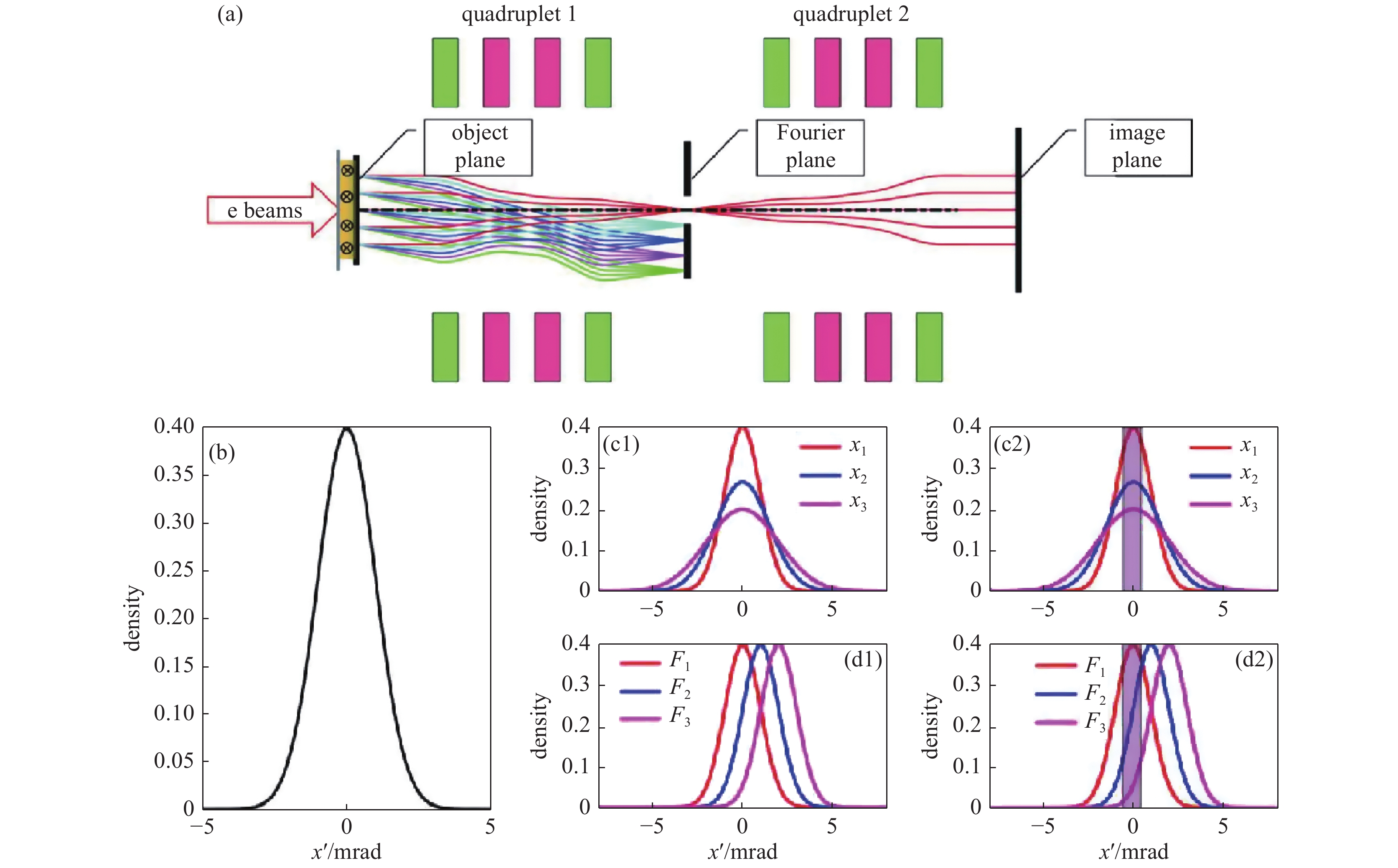
    Fig. 1. Schematic diagram of HEELR to make angle selection with an aperture. (a) The schematic of point-to-point imaging beamline with an aperture at the Fourier plane. (b) The angle distribution of incident electrons. (c1) and (c2) illustrate the electron angle distributions after target with different thicknesses and the corresponding position distributions at the Fourier plane. (d1) and (d2) are the electron angle distributions after penetrating the system with E/B field and the corresponding position distributions at the Fourier plane. The purple rectangular shadow indicates the aperture acceptance area
    The principle of areal density difference method to diagnose the areal density and E/B field. (a) The scattering angle distributions after the grille scattering target. Different color corresponds to different thicknesses (t1 and t2). (b) The surface plot with contour lines of Tr (t+t1, θ) and Tr (t+t2, θ). The intersection point of two contour lines with the same transmittance marks the solution (t, θ)
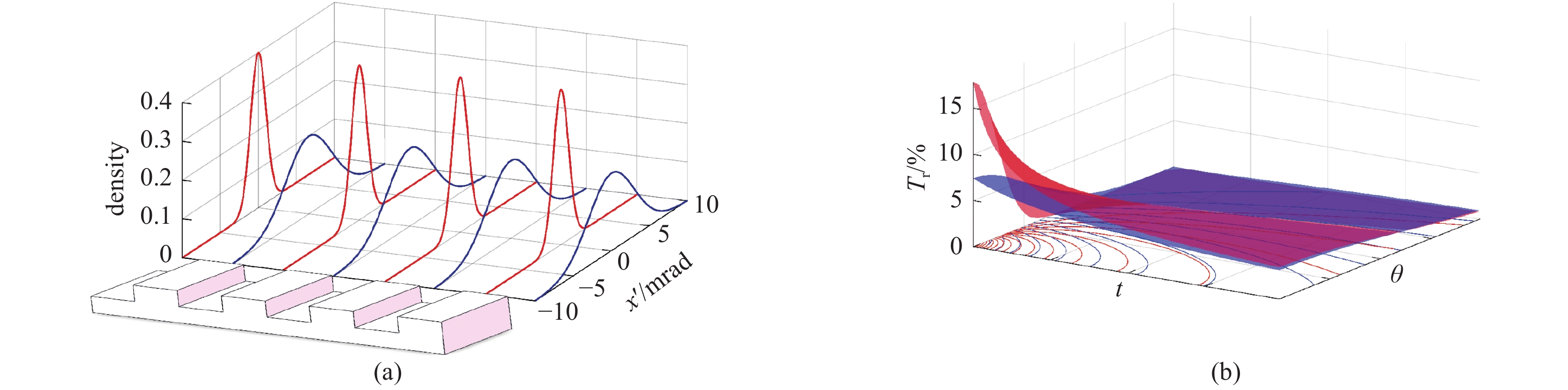
    Fig. 2. The principle of areal density difference method to diagnose the areal density and E/B field. (a) The scattering angle distributions after the grille scattering target. Different color corresponds to different thicknesses (t1 and t2). (b) The surface plot with contour lines of Tr (t+t1, θ) and Tr (t+t2, θ). The intersection point of two contour lines with the same transmittance marks the solution (t, θ)
    Overall design of the dual degrees of freedom diagnostic. (a) The incident beams will be scattered by the scattering target before penetrating the real diagnosed target. (b) The front view (perpendicular to the beam bunches) of the scattering target, different color indicates different thickness
    Fig. 3. Overall design of the dual degrees of freedom diagnostic. (a) The incident beams will be scattered by the scattering target before penetrating the real diagnosed target. (b) The front view (perpendicular to the beam bunches) of the scattering target, different color indicates different thickness
    (a) The wedge shape represents the hydrogen sample with gradient areal density. The color indicates the value of deflection angle from the E/B field and the coordinate system is as shown. (b) The ellipse shape aperture sets the upper limit of the angle acceptance as 1mrad. (c) The ring shape aperture which sets the angle acceptance as (1,2) mrad
    Fig. 4. (a) The wedge shape represents the hydrogen sample with gradient areal density. The color indicates the value of deflection angle from the E/B field and the coordinate system is as shown. (b) The ellipse shape aperture sets the upper limit of the angle acceptance as 1mrad. (c) The ring shape aperture which sets the angle acceptance as (1,2) mrad
    The analysis results when the angle acceptance of the ellipse shape aperture is 1 mrad
    Fig. 5. The analysis results when the angle acceptance of the ellipse shape aperture is 1 mrad
    The analysis results when the angle acceptance is set as from 1mrad to 2 mrad by a ring shape aperture
    Fig. 6. The analysis results when the angle acceptance is set as from 1mrad to 2 mrad by a ring shape aperture
    Jiahao Xiao, Yingchao Du, Haoqing Li, Yongtao Zhao, Liang Sheng. Dual degrees of freedom diagnosis with high energy electron lens radiography[J]. High Power Laser and Particle Beams, 2022, 34(6): 064010
    Download Citation