• Opto-Electronic Advances
  • Vol. 3, Issue 7, 200010-1 (2020)
Zexin Feng1、2, Dewen Cheng1、2, and Yongtian Wang1、2、*
Author Affiliations
  • 1Beijing Engineering Research Center of Mixed Reality and Advanced Display, School of Optics and Photonics, Beijing Institute of Tech-nology, Beijing, 100081, China
  • 2Beijing Key Laboratory of Advanced Optical Remote Sensing Technology, School of Optics and Photonics, Beijing Institute of Technology, Beijing 100081, China
  • show less
    DOI: 10.29026/oea.2020.200010 Cite this Article
    Zexin Feng, Dewen Cheng, Yongtian Wang. Iterative freeform lens design for prescribed irradiance on curved target[J]. Opto-Electronic Advances, 2020, 3(7): 200010-1 Copy Citation Text show less
    Sketch of the design geometry.
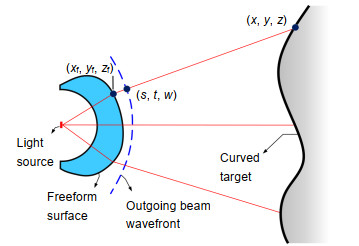
    Fig. 1. Sketch of the design geometry.
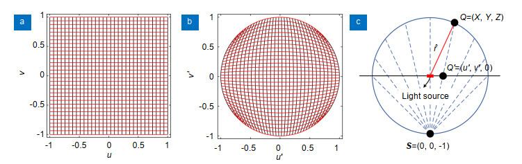
    The rectangular (u, v) grid (a) is transformed into a circular (u', v') grid (b) which is used as the stereographic coordinates (c).
    Fig. 2. The rectangular (u, v) grid (a) is transformed into a circular (u', v') grid (b) which is used as the stereographic coordinates (c).
    The flow diagram of the new IWT procedure for a curved target.
    Fig. 3. The flow diagram of the new IWT procedure for a curved target.
    The desired curved target. The side length of the target is 240 mm and the z values range from 73.80 mm to 132.42 mm.
    Fig. 4. The desired curved target. The side length of the target is 240 mm and the z values range from 73.80 mm to 132.42 mm.
    (a) The (u′, v′) grid corresponding to a uniform (u, v) grid on Ω={(u, v)|-0.94≤u≤0.94, -0.94≤v≤0.94} and (b) the final target grid for the first design (only showing 64×64 grid points for better visualization); (c) The final 3D freeform lens model and (d) its simulation results for a point like source (size: 10-3 mm×10-3 mm). (The unit of the irradiance: W/mm2)
    Fig. 5. (a) The (u′, v′) grid corresponding to a uniform (u, v) grid on Ω={(u, v)|-0.94≤u≤0.94, -0.94≤v≤0.94} and (b) the final target grid for the first design (only showing 64×64 grid points for better visualization); (c) The final 3D freeform lens model and (d) its simulation results for a point like source (size: 10-3 mm×10-3 mm). (The unit of the irradiance: W/mm2)
    (a) The (u′, v′) grid corresponding to a uniform (u, v) grid on Ω={(u, v)|-0.8≤u≤0.8, -0.8≤v≤0.8} and (b) the final target grid for the second design (only showing 64×64 grid points for better visualization); (c) The final 3D freeform lens model and (d) its simulation results for a point like source (size: 10-3 mm×10-3 mm). (The unit of the irradiance: W/mm2)
    Fig. 6. (a) The (u′, v′) grid corresponding to a uniform (u, v) grid on Ω={(u, v)|-0.8≤u≤0.8, -0.8≤v≤0.8} and (b) the final target grid for the second design (only showing 64×64 grid points for better visualization); (c) The final 3D freeform lens model and (d) its simulation results for a point like source (size: 10-3 mm×10-3 mm). (The unit of the irradiance: W/mm2)
    Simulated irradiance distributions for the first lens design when the source size is changed into (a) 1 mm× 1mm and (b) 2 mm× 2 mm respectively; simulated irradiance distributions for the second lens design when the source size is changed into (c) 1 mm × 1mm and (d) 2 mm × 2 mm respectively.(The unit of the irradiance: W/mm2; the unit of the length: mm)
    Fig. 7. Simulated irradiance distributions for the first lens design when the source size is changed into (a) 1 mm× 1mm and (b) 2 mm× 2 mm respectively; simulated irradiance distributions for the second lens design when the source size is changed into (c) 1 mm × 1mm and (d) 2 mm × 2 mm respectively. (The unit of the irradiance: W/mm2; the unit of the length: mm)
    Simulated irradiance distributions for the first lens design when the source-lens system is (a) 5 mm and (b) 10 mm closer to the target. Simulated irradiance distributions for the second lens design when the source-lens system is (c) 5 mm and (d) 10 mm closer to the target.(The unit of the irradiance: W/mm2; the unit of the length: mm)
    Fig. 8. Simulated irradiance distributions for the first lens design when the source-lens system is (a) 5 mm and (b) 10 mm closer to the target. Simulated irradiance distributions for the second lens design when the source-lens system is (c) 5 mm and (d) 10 mm closer to the target. (The unit of the irradiance: W/mm2; the unit of the length: mm)
    Zexin Feng, Dewen Cheng, Yongtian Wang. Iterative freeform lens design for prescribed irradiance on curved target[J]. Opto-Electronic Advances, 2020, 3(7): 200010-1
    Download Citation