
Yisi Dong, Peng-Cheng Hu, Haijin Fu, Hongxing Yang, Ruitao Yang, Jiubin Tan, "Long range dynamic displacement: precision PGC with sub-nanometer resolution in an LWSM interferometer," Photonics Res. 10, 59 (2022)
- Photonics Research
- Vol. 10, Issue 1, 59 (2022)
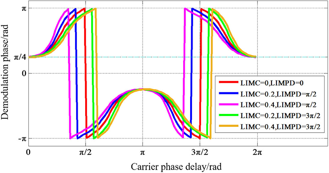
Fig. 1. Effects of CPD, LIMC, and LIMPD on demodulation phase in PGC demodulation.
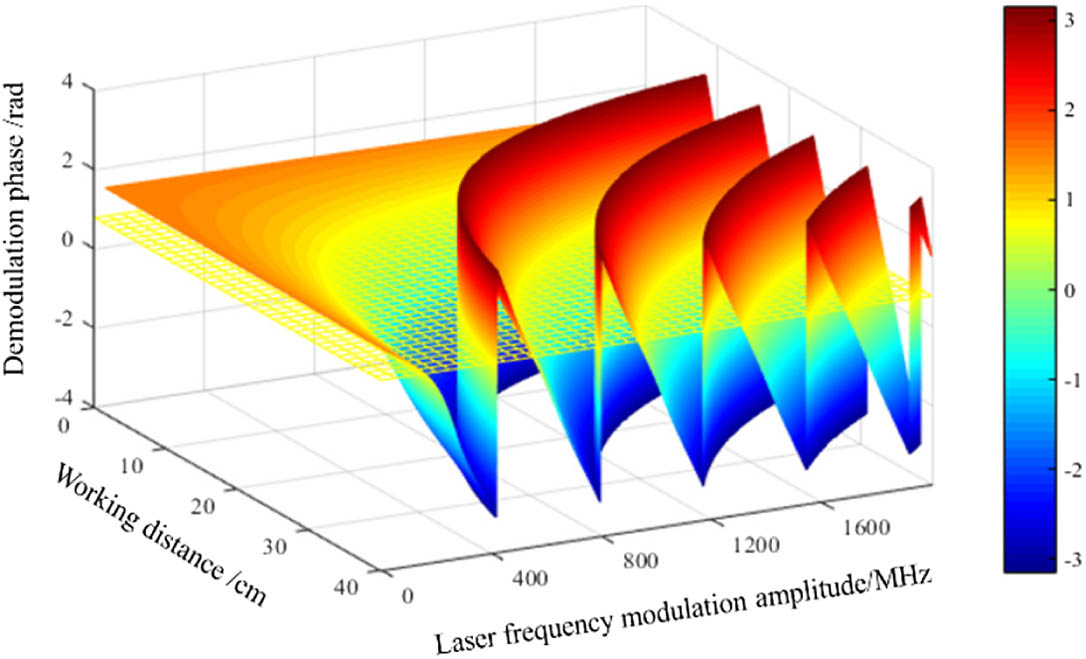
Fig. 2. Demodulation phase on both working distance and laser frequency modulation amplitude.
Fig. 3. Schematic of precision PGC demodulation in LWSM interferometer. M, reflector; APD, avalanche photodetector; SMF, single mode fiber; FC, fiber-optic circulator; DDS, direct digital synthesizer; ADC, analog-to-digital converter; LPF, low-pass filter; DAC, digital-to-analog converter; DFB, distributed feedback laser; EN, enabling end of a nonlinearity correction unit; PVD, peak value detection; SAD, signal amplitude detection.
Fig. 4. Experimental setups used for interferometer tests.
Fig. 5. CPD and LIMPD calculation results: blue traces and red traces correspond to the left ordinate; yellow traces and pink traces correspond to the right ordinate.
Fig. 6. (a) Phase modulation depth measured by two methods at different working distances. (b) PMD measured by two methods at interferometer operating point. (c) Demodulation results of two methods from 2.4 to 40 cm displacement.
Fig. 7. Lissajous diagrams for three methods under different phase delays and phase modulation depths.
Fig. 8. SINAD values for four methods under different phase delays and phase modulation depths.
Fig. 9. Experimental results for nanometer displacement measurement with 5 nm step size.
Fig. 10. Comparison experiment of large range displacement measurements.
Fig. 11. Experimental results of displacement measurement resolution of proposed interferometer and its long-term stability.


Set citation alerts for the article
Please enter your email address

© Copyright 2018-2021 | Chinese Laser Press. All Rights Reserved 沪ICP备15018463号-20