• Photonics Research
  • Vol. 10, Issue 10, 2434 (2022)
Navid Bani Hassan1、†, Fahimeh Dehkhoda2、†, Enyuan Xie1, Johannes Herrnsdorf1、*, Michael J. Strain1, Robert Henderson2, and Martin D. Dawson1
Author Affiliations
  • 1Institute of Photonics, Department of Physics, University of Strathclyde, Technology and Innovation Centre, Glasgow G1 1RD, UK
  • 2School of Engineering, Institute for Integrated Micro and Nano Systems, University of Edinburgh, Edinburgh EH9 3JL, UK
  • show less
    DOI: 10.1364/PRJ.455574 Cite this Article Set citation alerts
    Navid Bani Hassan, Fahimeh Dehkhoda, Enyuan Xie, Johannes Herrnsdorf, Michael J. Strain, Robert Henderson, Martin D. Dawson. Ultrahigh frame rate digital light projector using chip-scale LED-on-CMOS technology[J]. Photonics Research, 2022, 10(10): 2434 Copy Citation Text show less
    Photograph of the mounted LED projector on CMOS chip, co-packaged with an FPGA controller. The projector is here displaying a diagonal cross pattern. Magnified inset images show the mounted LED array on the CMOS chip and a zoomed view of the LED pixel contact pads, imaged through the sapphire substrate.
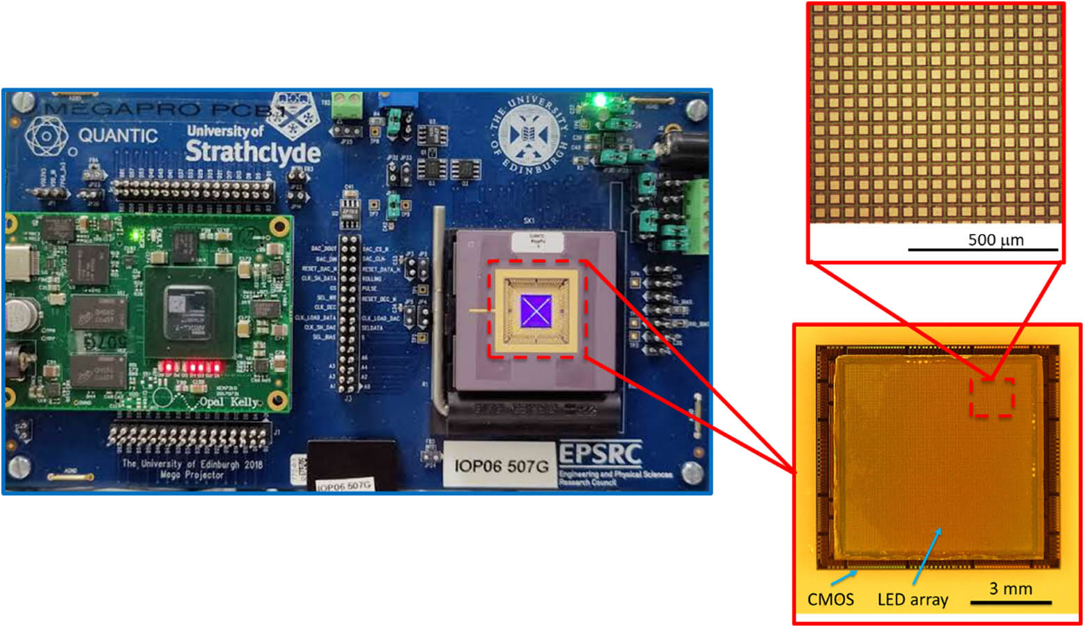
    Fig. 1. Photograph of the mounted LED projector on CMOS chip, co-packaged with an FPGA controller. The projector is here displaying a diagonal cross pattern. Magnified inset images show the mounted LED array on the CMOS chip and a zoomed view of the LED pixel contact pads, imaged through the sapphire substrate.
    Simplified schematic of the driver circuit for one pixel, showing 5-bit DAC, in-pixel memory, and control signals.
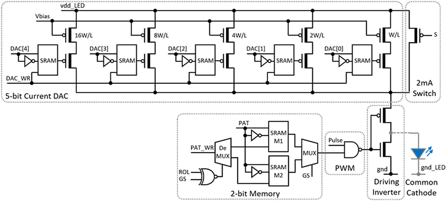
    Fig. 2. Simplified schematic of the driver circuit for one pixel, showing 5-bit DAC, in-pixel memory, and control signals.
    Simplified timing diagram of the digital control signals supplied to the CMOS by an FPGA.
    Fig. 3. Simplified timing diagram of the digital control signals supplied to the CMOS by an FPGA.
    (a) Optical output power of a single pixel for different DAC settings; (b) gray-scale image from the LED projector chip using the DAC gray levels; (c) digital version of the image projected in (b).
    Fig. 4. (a) Optical output power of a single pixel for different DAC settings; (b) gray-scale image from the LED projector chip using the DAC gray levels; (c) digital version of the image projected in (b).
    (a) Measured eye diagram for 104 transmitted frames at 0.25 Mfps rate and (b) associated signal level histogram; (c) measured eye diagram at 0.4 Mfps and (d) associated signal level histogram.
    Fig. 5. (a) Measured eye diagram for 104 transmitted frames at 0.25 Mfps rate and (b) associated signal level histogram; (c) measured eye diagram at 0.4 Mfps and (d) associated signal level histogram.
    Representative LED projection frames captured with a high-speed camera at 0.8 Mfps. Visible is the partial footprint of the last two columns of the LED chip: (a) frame #1 C2B, (b) frame #2 C2B, (c) frame #1 C2C, and (d) frame #2 C2C. (e) Measured photosignal from global array toggling at 2 Mfps.
    Fig. 6. Representative LED projection frames captured with a high-speed camera at 0.8 Mfps. Visible is the partial footprint of the last two columns of the LED chip: (a) frame #1 C2B, (b) frame #2 C2B, (c) frame #1 C2C, and (d) frame #2 C2C. (e) Measured photosignal from global array toggling at 2 Mfps.
    (a) Optical micrograph of a pattern displayed in nanosecond pulsed mode; (b) optical waveform of 5 ns long pulses as a function of number of pulsing pixels; (c) optical pulse duration as a function of the number of pixels for a 5 ns input pulse; (d) optical pulse duration as a function of electrical input pulse duration; (e) relative delay of the pulses emitted by individual pixels within one row; (f) relative delay of the pulses emitted by individual pixels within one column.
    Fig. 7. (a) Optical micrograph of a pattern displayed in nanosecond pulsed mode; (b) optical waveform of 5 ns long pulses as a function of number of pulsing pixels; (c) optical pulse duration as a function of the number of pixels for a 5 ns input pulse; (d) optical pulse duration as a function of electrical input pulse duration; (e) relative delay of the pulses emitted by individual pixels within one row; (f) relative delay of the pulses emitted by individual pixels within one column.
    (a) Total chip pulse energy for 5 ns-long pulses as a function of the number of active pixels at 10 MHz, and (b) pulse energy per pixel as a function of number of active pixels.
    Fig. 8. (a) Total chip pulse energy for 5 ns-long pulses as a function of the number of active pixels at 10 MHz, and (b) pulse energy per pixel as a function of number of active pixels.
    Comparison of the LED array presented here with other 2D programmable pattern sources, with pixel count and frame rate as parameters. Note the scaling potential of our technology in terms of number of pixels. Details of individual devices are provided in Data File 1.
    Fig. 9. Comparison of the LED array presented here with other 2D programmable pattern sources, with pixel count and frame rate as parameters. Note the scaling potential of our technology in terms of number of pixels. Details of individual devices are provided in Data File 1.
    Schematic diagram of the signal distribution circuit of the CMOS driver chip.
    Fig. 10. Schematic diagram of the signal distribution circuit of the CMOS driver chip.
    Detailed timing diagram of gray-scale and binary-pattern loading.
    Fig. 11. Detailed timing diagram of gray-scale and binary-pattern loading.
    Oscilloscope traces of the signal “LOAD_CLK” in Fig. 11 when (a) loading a binary pattern and (b) loading a gray-scale pattern.
    Fig. 12. Oscilloscope traces of the signal “LOAD_CLK” in Fig. 11 when (a) loading a binary pattern and (b) loading a gray-scale pattern.
    Statistics from the camera communications experiment. (a) Histogram of time-average pixel intensity, (b) BER at 0.25 Mfps versus time-averaged pixel intensity, and histograms of BER at (c) 0.25 Mfps and (d) 0.4 Mfps.
    Fig. 13. Statistics from the camera communications experiment. (a) Histogram of time-average pixel intensity, (b) BER at 0.25 Mfps versus time-averaged pixel intensity, and histograms of BER at (c) 0.25 Mfps and (d) 0.4 Mfps.
    Navid Bani Hassan, Fahimeh Dehkhoda, Enyuan Xie, Johannes Herrnsdorf, Michael J. Strain, Robert Henderson, Martin D. Dawson. Ultrahigh frame rate digital light projector using chip-scale LED-on-CMOS technology[J]. Photonics Research, 2022, 10(10): 2434
    Download Citation