The 975 nm multimode diode lasers with high-order surface Bragg diffraction gratings have been simulated and calculated using the 2D finite difference time domain (FDTD) algorithm and the scattering matrix method (SMM). The periods and etch depth of the grating parameters have been optimized. A board area laser diode (BA-LD) with high-order diffraction gratings has been designed and fabricated. At output powers up to 10.5 W, the measured spectral width of full width at half maximum (FWHM) is less than 0.5 nm. The results demonstrate that the designed high-order surface gratings can effectively narrow the spectral width of multimode semiconductor lasers at high output power.
Laser diodes operating at 975 nm are key pumping sources for erbium-doped fiber and ytterbium-doped fiber lasers[1−3], which demand wavelength stability, narrow output spectral width and high output power of laser sources[4, 5]. Distributed feedback (DFB) and distributed Bragg reflector (DBR) structures[6] have been widely used to compress the spectral width of laser diodes. Compared with DFB structures[7], DBR structures can offer a relatively simpler manufacturing process and avoid introducing defects associated with the secondary epitaxial growth needed in DFB technology.
The fabrication process of the low diffraction level DBR grating is relatively intricate due to their typical periods of a few hundred nanometers, although they do not incur diffraction losses. Electron beam lithography (EBL) is generally employed to accomplish these grating structures[8, 9]. In contrast, the high-order DBR with a diffraction level N larger than 10 and periods exceeding 1 μm can be successfully fabricated utilizing conventional contact-mode ultraviolet exposure lithography, reducing manufacturing costs[10].
The high-order DBR structures have been extensively researched in recent years. In 2015, Zolotarev et al. conducted a theoretical study of high-order diffractive Bragg gratings using coupled-mode theory and pointed out that the interference radiation modes (IRM) brought about by the high-order diffraction affect the cavity modes propagating within the waveguide, thus affecting the performance of the lasers[11]. In 2019, Zolotarev et al. fabricated semiconductor lasers with 13th and 16th order surface DBR, achieving an output power of 3 W in the CW mode and a spectral width of full width at halfmaximum (FWHM) of less than 0.3 nm at a stripe width of 100 μm and a cavity length of 3 mm[12].
In this paper, the high-order DBR lasers based on the AlGaAs/InGaAsP/GaAs system have been designed using the finite difference time domain (FDTD)[13] and scattering matrix method (SMM)[14] algorithms. The properties of a 100th-order grating have been investigated. The effect of grating structure parameters, such as the grating period number and etching depth, on grating reflectivity and transmissivity has been calculated and analyzed. Appropriate parameters for fabricating the high-order DBR lasers have been selected. Device testing results show that the theoretical design is feasible.
Theory
The high-order diffraction can be disregarded for first-order grating, and only the zero-order diffraction needs to be taken into consideration, resulting in no diffraction losses. As the period of the grating increases, the high-order diffraction becomes significant, and diffraction effects occur when the period is larger than the lasing wavelength in the medium[15]. The SMM has many advantages in dealing with such problems: the computational process converges unconditionally, and the parameters of the matrix have a very clear physical meaning. On the other hand, the FDTD algorithm provides an exact solution to Maxwell's equations in the plane of the device. The FDTD algorithm has been greatly developed in recent years with the improvement of computer performance[13]. The SMM can be given by the following equation, expressed as[14]:
The column vectors , , and denote the mode amplitudes propagating forward and backward immediately adjacent to the ith layer, where the scattering matrix is given by:
For two adjacent scattering matrices and their combined scattering matrix is denoted by:
An operation "" can be defined such that:
For a multilayer structure:
This is the scattering matrix of the whole grating region. However, when incorporating the grating into the whole laser device structure, the scattering matrix at the interfaces connecting with the front and rear structures is also considered. These are expressed as for the reflection region in front of the grating and for the transmissive region behind the grating. Since the significance of the introduction of these two scattering matrices is to integrate the scattering matrix of the grating region into the entire semiconductor laser structure, these two matrices only play a connecting role, so there is no actual thickness. At this point, we can establish the global scattering matrix as follows:
For a single period of the grating, the matrix elements of the scattering matrix can be computed using the FDTD algorithm. The information about the grating scattering and interaction with the incident light can be obtained by simulating the behavior of electromagnetic waves within a single period of the grating. Based on the scattering matrix elements for a single period, the scattering matrix of the entire grating region can be obtained using the SMM algorithm, which takes into account the periodic processing of the grating.
Taking as an example, the calculation of the scattering matrix of the grating cell using the FDTD algorithm requires two operations for forward and backward propagation, setting up two mode light sources, respectively. However, since the structure of the calculated grating cell is symmetric with and in this case, only one transmission calculation for forward propagation is needed, which greatly reduces the computational workload.
Therefore, only the energy reflected back from port 1 and the energy transmitted through port 2 need to be collected and normalized to obtain the and values of the S matrix. For the rest of the matrix elements, they can be replicated from and .
Epitaxial structure model simulation
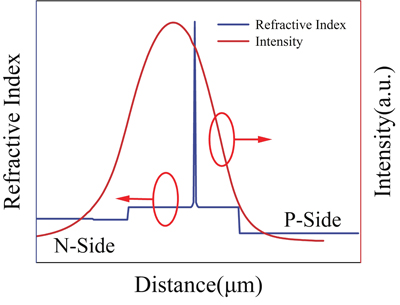
In this study, the epitaxial structure used and its optical field distribution are shown in Fig. 1, which allows for a very low internal loss and thus the highest possible output power in the fabrication of high-order gratings, as more information about the epitaxial structure has been described in detail in a previously published paper by our research group[16]. The epitaxial structure is as shown in Table 1.
Figure 1.(Color online) Refractive index and light field distribution of the asymmetric large optical cavity structure.
The refractive index of the AlGaAs material used in the model was derived from a fitted formula given by Adachi[17]. Similarly, the refractive index of the InGaAsP quantum well material was obtained from a fitted formula given by Seifert[18]. These fitted formulas provide an accurate representation of the refractive index properties of the respective materials.
In the process of determining the grating period and etch slot width for the optimal grating structure, only the fundamental mode light source was used in order to reduce the complexity of the calculation, which is commonly employed in semiconductor laser simulations, as the fundamental mode has a higher confinement factor and is more likely to achieve lasing. Focusing on the fundamental mode, the computational requirements can be reduced while the essential characteristics of the laser device can be captured.
Figure 2.(Color online) Schematic diagram of the model for a single grating cycle
A 100th-order grating with a period of 7.165 μm and a slot width of 1.69 μm has been selected. At this point, ordinary ultraviolet lithography can meet the lithographic accuracy requirements. As shown in Fig. 2. To accurately simulate the light absorption into the air and into the substrate, the perfectly matched layer (PML) boundary conditions are set at a position greater than 2 times the wavelengths above the epitaxial structure and within the GaAs substrate, respectively. The purpose of these boundary conditions is to effectively absorb any outgoing waves, preventing reflections and ensuring accurate simulation results. In the simulation setup, the ports are placed on both sides of the grating structure, served as multiple purposes of facilitating the operation of the light source, monitoring of the energy of the light source, normalizating the energy for accurate calculations, and calculating of the scattering matrix elements.
Grating design
Determination of the grating period and slot width
The period and slot width of the grating are the first parameters to be determined. Two parameters need to be determined in the scan, one is the width of the grating period () and the other is the slot width (). When the number of periods is set to 10 and the etch depth is set to 1.45 μm, the reflectivity distribution at the wavelength of 975 nm for different combinations of and have been calculated as shown in Fig. 3. The and of the Bragg grating can be determined using the following formula[19]:
Figure 3.(Color online) (a) The grating period and etch slot width versus grating transmittance for high precision scanning. (b) The grating period and etch slot width versus grating reflectance for high precision scanning.
Here, p and q are integers, denotes the diffraction order of the grating, denotes the center wavelength of the Bragg grating, is the effective refractive index in the slot, is the effective refractive index of the entire epitaxial structure. In this case, and .
Substituting m = 100 into the calculation yields the period of a 100th-order grating. Fine parameter scanning was conducted in its vicinity, and the scanning results are illustrated in Fig. 3. It can be seen from Fig. 3 that the peak reflectivity and the grating period show an obvious periodic correlation. The enhanced grid resolution achieved through the high-precision scan allows for a more detailed visualization of the spectrum. One noteworthy observation is the separation between adjacent reflection peaks, denoted as ΔT, which is approximately equal to 145 nm. This observation closely correlates with the calculated value of ΔT = 144 nm obtained from Eqs. (7) and (8). The clear confirmation of this agreement provides further validation for the accuracy of our calculations and supports the reliability of our research.
Effect of the etch depth and number of periods
Considering factors such as reflectivity, transmissivity, and compatibility with the broad-area laser diode fabrication process, high-order gratings with a period length of 7.165 μm and a slot width of 1.69 μm have been selected. A specific analysis has been performed to further explore the relationship between the etch depth and the reflectivity of the high-order gratings. In this analysis, the number of grating periods was set to 25, and the etch depth was varied from 1.15 to 1.55 μm. The wavelength range considered for this analysis is from 965 to 980 nm. The scan step used in this calculation was set to 200 nm. The results of this calculation are shown in Fig. 4.
Figure 4.(Color online) (a) Relationship between etching depth and reflectivity for a grid period of 25. (b) Transmittance of gratings at different etching depths.
According to Fig. 4(a), it is clear that the reflectivity of the grating initially increases and then decreases with increasing etch depth. The reflectivity reaches a peak value of 20% at an etch depth of 1.5 μm and then decreases. This observed decrease in reflectance can be attributed to the increase in higher-order scattering losses of the grating as the etch depth increases. These higher-order scattering losses have an impact on the overall reflectance characteristics of the grating. As can be seen in Fig. 4(b), the transmittance of the grating decreases as the etch depth increases. This observation can be attributed to the corresponding increase in the diffraction loss of the grating.
Furthermore, the center wavelength of the Bragg grating undergoes a blue shift as the etch depth increases. This shift can be attributed to the decrease in the effective refractive index in the etched grooves. According to Eqs. (7) and (8), the reduction in the effective refractive index leads to a decrease in the center wavelength of higher-order DBR. This observation is consistent with the theoretical prediction.
In order to investigate the effect of the grating period number on the grating performance, the etch depth was kept at a constant of 1.35 μm. The results of these calculations are presented in Fig. 5(a) and Fig. 6(b). It is clearly shown that an increase in the number of grating periods leads to a corresponding increase in the grating reflectance and a decrease in its transmittance. This can be attributed to the enhanced optical feedback within the grating. Additionally, the FWHM of the reflectance spectrum decreases as the number of grating periods increases. This behavior is consistent with the coupling mode theory for low-order gratings, which has been previously described in related literature[20].
Figure 5.(Color online) (a) Grating reflectance and transmittance versus grating period for a grating etching depth of 1.35 μm. (b) Transmittance of gratings at different grating period numbers.
Threshold performance of the high-order grating lasers diodes
The incorporation of high-order diffraction gratings in semiconductor lasers has the advantage of reducing the spectral width. However, it must be acknowledged that high-order DBR gratings also introduce additional losses that cannot be ignored. As seen in the work by Zolotarev et al., utilizing high-order gratings as the high reflector in lasers leads to unacceptable losses, significantly diminishing the laser performance. Therefore, in this context, we introduce high-order gratings as the low reflector in the laser setup. Utilizing the previously determined parameters of 25 grating periods, a period of 7.165 μm, and a slot width of 1.69 μm, we can analyze the effect of high-order gratings on the threshold performance of semiconductor lasers. For general laser diodes (LD), the threshold gain can be expressed using Eq. (9)[21]:
Here, represents the internal losses, is the length of gain section, and are the reflectivities of the two cavity facets. In the equation, the first term represents the internal losses of the semiconductor laser, which include various loss mechanisms within the laser cavity. These internal losses can arise from factors such as free carrier absorption, material absorption, and scattering losses. The second term in the equation represents the cavity facet losses, which refer to the losses occurring at the ends of the laser cavity. These losses can arise from factors such as cavity facet reflectivity, mode mismatch, and cavity facet scattering. By reducing both the internal losses and the cavity facet losses at the target wavelength, it is possible to achieve a narrow spectral width from high-order gratings.
In the study conducted by Kang et al., they proposed a formula to calculate cavity facet losses by considering the length without current injection subtracted from the total cavity length. However, this formula does not take into account the effect of high-order diffraction in the HO-DBR, which led to a deviation between their experimental and calculated results[21].
To address this limitation, we make an additional adjustment to their formula by approximating that the scattering losses in the HO-DBR lead to a linear decay of the optical energy. We treat the entire semiconductor laser as a unified system, considering that the scattering loss affects the entire resonant cavity of the semiconductor laser.
The scattering loss of the HO-DBR can be quantified using the linear attenuation Eq. (10), which describes the decrease of optical energy due to scattering:
where represents the energy of the incident light as it enters the high-order gratings, while refers to the energy that is reflected back into the laser and transmitted out of the laser after scattering by the high-order grating. The parameter represents the length of the laser cavity.
By incorporating this linear decay formulation into the overall analysis, we consider the scattering loss caused by high-order diffraction gratings in the semiconductor laser. This refinement allows us to obtain a more precise estimation of the total losses and evaluate the impact of high-order grating on the laser performance.
Calculations were performed for high-order gratings with 25 grating periods for different etch depths and a device cavity length of 5500 μm. The results are shown in Figs. 6(a) and 6(b). The corresponding calculated parameters are listed in Table 2.
Figure 6.(Color online) (a) Effect of etch depth on threshold gain. (b) Effect of grating period on threshold gain.
By combining Eqs. (9) and (10), we derive Eq. (11), which represents an equation describing the threshold gain of the HO-DBR lasers. This equation takes into account both the internal losses and the cavity facet losses. As the etching depth increases, the internal losses caused by high-order diffraction also increase. However, simultaneously, the reflectivity of the grating increases, leading to a decrease in cavity facet losses. These two factors counterbalance each other, resulting in a threshold gain that remains relatively constant for different etch depths.
Fig. 6(a) shows that the threshold performance of the HO-DBR lasers is relatively insensitive to changes in etch depth over the range investigated. It implies that optimizing the etch depth might not have a significant effect on the threshold gain, while other factors, such as the number of grating periods play a more important role in improving the laser performance.
Fig. 6(b) shows the observed decrease in the FWHM of the threshold gain peak as the grating period number increases, indicating that more grating periods are required to achieve a narrower spectral width in the HO-DBR lasers. This behavior is consistent with the coupling mode theory for low-order gratings, where an increase in the number of grating periods enhances the feedback of light within the grating. On the other hand, an increase in the grating period leads to a decrease in Lgain and an increase in scattering loss and grating reflectivity, all of which affect the threshold gain simultaneously. However, since the cavity length of our device is significantly longer than the grating area (L : Lgratings > 10 : 1), some additional losses caused by the increase in the number of grating periods become negligible. Nonetheless, the lowest threshold gain in our calculations is observed at N = 25, at 4.011 cm-1.
Further analysis and experimental investigations are necessary to fully understand the interactions between etch depth, reflectivity, transmissivity, and threshold gain in the HO-DBR lasers and to optimize their performance.
Device fabrication and results
The epitaxial structure shown in Fig. 1 was grown on an n-GaAs substrate using metal–organic chemical vapor deposition (MOCVD) technology. To transfer the mesa and grating structure, both measuring 230 μm in width, to a SiO2 hard mask, a conventional photolithography technique was used. Subsequently, the mesa (200 nm) and grating structure (1.3 μm) are etched using inductively coupled plasma (ICP) etching through a zonal etching process. Upon removing the SiO2 hard mask, a new layer of SiO2 was regenerated as an insulating layer using plasma-enhanced chemical vapordeposition (PECVD).The image of the grating after etching is shown in Fig. 7. 230 μm wide Ti/Pt/Au P-contact stripes were fabricated on the gain section only. The HO-BDG section was passivated using 200 nm thick SiO2.
The subsequent steps involve thinning, N-side polishing, and N-side electrode preparation. The front side (HO-BDG part) of the laser chip has an anti-reflective coating (R1 < 0.2%) and the back side (gain part) has a highly reflective coating (R2 ≥ 95%). Finally, the laser is cleaved into single chips of 500 × 5500 μm2 and packaged P-side down on aluminum nitride heat sinks.
The packaged HO-DBR-LD was tested in CW (continuous wave) mode, and the results are shown in Fig. 8(a). The laser demonstrates a slope efficiency of 0.83 W/A. The electro-optical conversion efficiency was measured to be 44.1%. The laser achieved an output power of 10.5 W when an injection current of 15 A was applied.
Figure 8.(Color online) (a) P−I−V curve of a HO-BDG-LD with 240 μm width; (b) P−I−V curve of a FP-LD without grating.
Fig. 8(a) shows the laser spectrum at this operating point with a FWHM of 0.47 nm. It is worth noting that the spectral width is significantly reduced compared to the FP-LD without the grating, as shown in Fig. 8(b).
Conclusion
In conclusion, the 975 nm semiconductor laser with the high-order diffraction gratings have been successfully designed and fabricated. The diffraction grating with a period of 7.165 μm and the periods number of 25 have been designed based on the FDTD and SMM algorithms. The laser achieved a narrow spectral width of 0.47 nm at an output power of 10.5 W. In addition, the entire fabrication process of the adopted general ultraviolet (UV) lithography is compatible with the fabrication process of high-power wide-contact semiconductor lasers for mass production.