• Infrared and Laser Engineering
  • Vol. 50, Issue 3, 20210033 (2021)
Liang Mei1, Zheng Kong1, Hongze Lin2, Ruonan Fei1, Yuan Cheng1, Zhenfeng Gong1, Ke Chen1, Kun Liu1, and Dengxin Hua1、3
Author Affiliations
  • 1School of Optoelectronic Engineering and Instrumentation Science, Dalian University of Technology, Dalian 116024, China
  • 2School of Automation, Hangzhou Dianzi University, Hangzhou 310018, China
  • 3School of Mechanical and Precision Instrument Engineering, Xi'an University of Technology, Xi’an 710048, China
  • show less
    DOI: 10.3788/IRLA20210033 Cite this Article
    Liang Mei, Zheng Kong, Hongze Lin, Ruonan Fei, Yuan Cheng, Zhenfeng Gong, Ke Chen, Kun Liu, Dengxin Hua. Recent advancements of the lidar technique based on the Scheimpflug imaging principle (Invited)[J]. Infrared and Laser Engineering, 2021, 50(3): 20210033 Copy Citation Text show less
    Optical layout of the Scheimpflug imaging principle. is the focal length of the receiving telescope沙氏成像原理示意图。f是接收望远镜的焦距
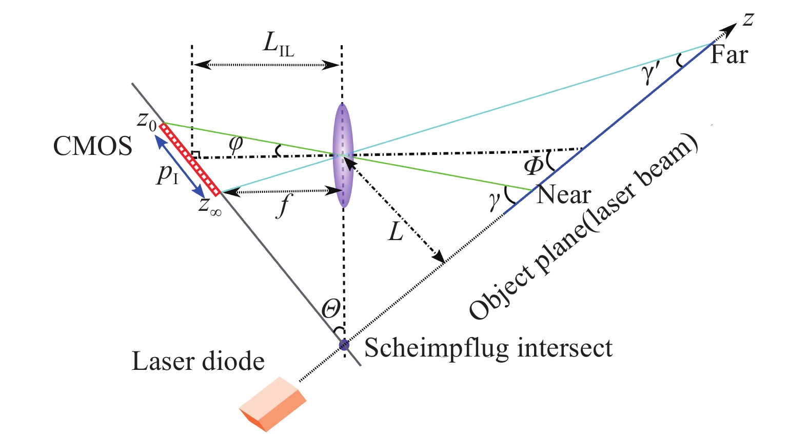
    Fig. 1. Optical layout of the Scheimpflug imaging principle. is the focal length of the receiving telescope 沙氏成像原理示意图。f是接收望远镜的焦距
    (a) Relationships between the pixel and the measurement distance with different optical configurations; (b) Relationship between the range resolution and the measurement distance. System parameters: f is the focus of the receiving telescope, separation refers to the distance between the transmitter and the receiver, pixel width: 5.5 µm, pixel number: 2048×1024, (a) 不同配置的沙氏成像系统像素与测量距离的对应关系;(b)距离分辨率与测量距离之间的关系。f为接收望远镜的焦距,separation表示发射端与接收端之间的间隔,相机参数:像素大小为5.5 μm,像元数量为 2048×1024,相机倾角为45˚
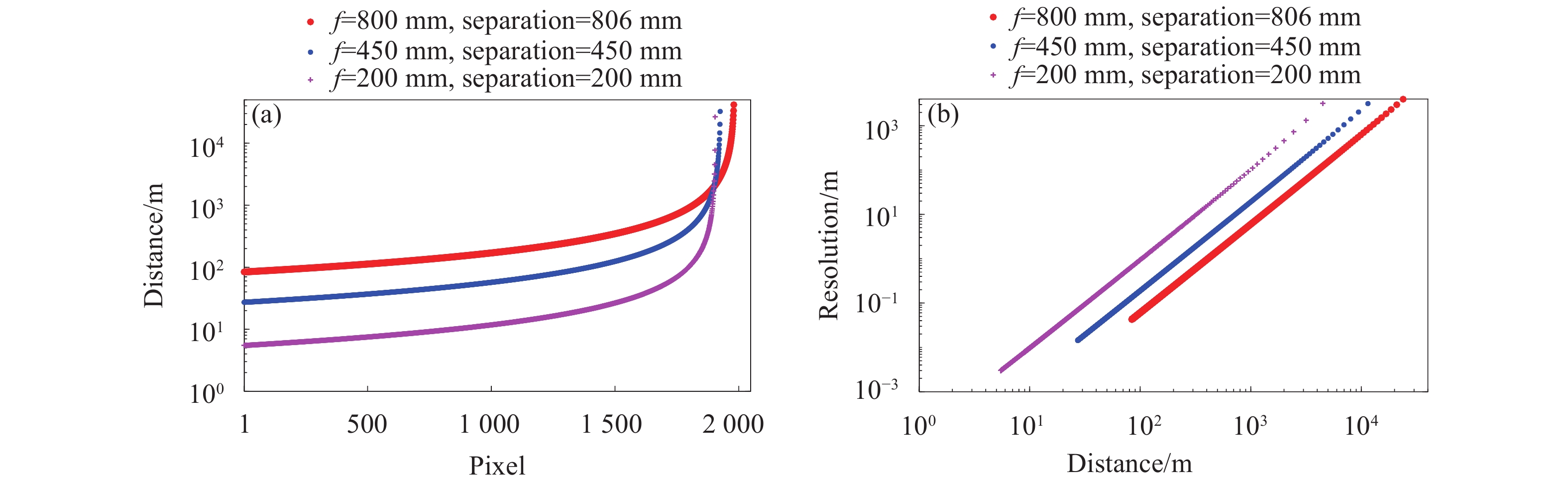
    Fig. 2. (a) Relationships between the pixel and the measurement distance with different optical configurations; (b) Relationship between the range resolution and the measurement distance. System parameters: f is the focus of the receiving telescope, separation refers to the distance between the transmitter and the receiver, pixel width: 5.5 µm, pixel number: 2048×1024, (a) 不同配置的沙氏成像系统像素与测量距离的对应关系;(b)距离分辨率与测量距离之间的关系。f为接收望远镜的焦距,separation表示发射端与接收端之间的间隔,相机参数:像素大小为5.5 μm,像元数量为 2048×1024,相机倾角为45˚
    (a) Architecture of the Scheimpflug atmospheric lidar system based on a Newtonian telescope; (b) Typical pixel-intensity lidar signal; (c) Range-intensity lidar signal transferred by pixel-range lidar signal
    Fig. 3. (a) Architecture of the Scheimpflug atmospheric lidar system based on a Newtonian telescope; (b) Typical pixel-intensity lidar signal; (c) Range-intensity lidar signal transferred by pixel-range lidar signal
    (a) Measurement geometry, (b) physical diagram of the pulsed lidar system, and (c) physical diagram of the Scheimpflug lidar system. The rain-proofed SLidar system was placed on the rooftop while the pulsed lidar system was located inside a laboratory
    Fig. 4. (a) Measurement geometry, (b) physical diagram of the pulsed lidar system, and (c) physical diagram of the Scheimpflug lidar system. The rain-proofed SLidar system was placed on the rooftop while the pulsed lidar system was located inside a laboratory
    Time-range evolution maps of range-corrected log-scale lidar signals measured by (a) the pulsed lidar system and (b) the SLidar system while slope measurement from 11th June 2019 to 12th June 2019. The elevation angle was about 30˚
    Fig. 5. Time-range evolution maps of range-corrected log-scale lidar signals measured by (a) the pulsed lidar system and (b) the SLidar system while slope measurement from 11th June 2019 to 12th June 2019. The elevation angle was about 30˚
    Time-space evolution map of the atmospheric backscattering signals measured by an 808 nm all-day SLidar system
    Fig. 6. Time-space evolution map of the atmospheric backscattering signals measured by an 808 nm all-day SLidar system
    Measurement principles of atmospheric polarization lidar. (a) Dual-channel pulsed polarization lidar, (b) Polarization Scheimpflug lidar based on the time-division multiplexing scheme, (c) Polarization-sensitive imaging lidar utilizing a polarized image sensor
    Fig. 7. Measurement principles of atmospheric polarization lidar. (a) Dual-channel pulsed polarization lidar, (b) Polarization Scheimpflug lidar based on the time-division multiplexing scheme, (c) Polarization-sensitive imaging lidar utilizing a polarized image sensor
    Time-space map of the linear volume depolarization ratio measured by the polarization-sensitive imaging lidar in Dec. 2019
    Fig. 8. Time-space map of the linear volume depolarization ratio measured by the polarization-sensitive imaging lidar in Dec. 2019
    (a) Portable SLidar atmospheric system based on a refracting telescope. Transmitter: Φ=100 mm, f=600 mm; Refracting telescope receiver: Φ=150 mm, f=750 mm; Separation between transmitter and receiver is 756 mm. (b) Portable SLidar atmospheric system based on a Newtonian telescope. Transmitter: Φ=100 mm, f=600 mm; Newtonian telescope receiver: Φ=200 mm, f=800 mm; Separation between transmitter and receiver is 806 mm
    Fig. 9. (a) Portable SLidar atmospheric system based on a refracting telescope. Transmitter: Φ=100 mm, f=600 mm; Refracting telescope receiver: Φ=150 mm, f=750 mm; Separation between transmitter and receiver is 756 mm. (b) Portable SLidar atmospheric system based on a Newtonian telescope. Transmitter: Φ=100 mm, f=600 mm; Newtonian telescope receiver: Φ=200 mm, f=800 mm; Separation between transmitter and receiver is 806 mm
    (a) Atmospheric backscattering intensity distribution map and (b) atmospheric extinction coefficient retrieving map measured by a scanning SLidar system. The SLidar system was placed on the roof of a shopping mall in Changli, Qinhuangdao City, Hebei Province
    Fig. 10. (a) Atmospheric backscattering intensity distribution map and (b) atmospheric extinction coefficient retrieving map measured by a scanning SLidar system. The SLidar system was placed on the roof of a shopping mall in Changli, Qinhuangdao City, Hebei Province
    (a) Schematic and (b) photograph of the three-wavelength polarization SLidar system developed at Dalian University of Technology
    Fig. 11. (a) Schematic and (b) photograph of the three-wavelength polarization SLidar system developed at Dalian University of Technology
    (a) Time-range evolution map of the linear volume depolarization ratio at 808 nm,(b) Temporal evolution curves of the median of linear volume depolarization ratio and the median of Ångström exponent
    Fig. 12. (a) Time-range evolution map of the linear volume depolarization ratio at 808 nm,(b) Temporal evolution curves of the median of linear volume depolarization ratio and the median of Ångström exponent
    Schematic of NO2 absorption spectrum, the and laser spectraNO2吸收光谱及激光器发射光谱示意图
    Fig. 13. Schematic of NO2 absorption spectrum, the and laser spectra NO2吸收光谱及激光器发射光谱示意图
    (a) Architecture of the 2D fluorescence SLidar principle; (b) Data cloud reconstruction result of a grapefruit tree with the 2D fluorescence SLidar 5 m away, the dot cloud intensity represents the signal intensity ratio of red channel to blue channel of image sensor
    Fig. 14. (a) Architecture of the 2D fluorescence SLidar principle; (b) Data cloud reconstruction result of a grapefruit tree with the 2D fluorescence SLidar 5 m away, the dot cloud intensity represents the signal intensity ratio of red channel to blue channel of image sensor
    Architecture of the inelastic scattering hyperspectral SLidar system
    Fig. 15. Architecture of the inelastic scattering hyperspectral SLidar system
    Atmospheric conditionsLVDR at 808 nmA520/808A405/808LVDR at 532 nm by Zhang et al.[26]A532/1064 by Muller et al.[27]
    Dust0.25-0.30−0.04-0.19−0.09-0.16>0.20.2±0.2
    Haze0.06-0.080.1-1.00.2-0.9<0.0751.0±0.5
    Clean0.05-0.062.0-3.51.9-3.0<0.075
    Table 1. [in Chinese]
    Liang Mei, Zheng Kong, Hongze Lin, Ruonan Fei, Yuan Cheng, Zhenfeng Gong, Ke Chen, Kun Liu, Dengxin Hua. Recent advancements of the lidar technique based on the Scheimpflug imaging principle (Invited)[J]. Infrared and Laser Engineering, 2021, 50(3): 20210033
    Download Citation