
Woongseob Han, Jae-Won Lee, Jung-Yeop Shin, Myeong-Ho Choi, Hak-Rin Kim, Jae-Hyeung Park. Varifocal occlusion in an optical see-through near-eye display with a single phase-only liquid crystal on silicon[J]. Photonics Research, 2024, 12(4): 833
- Photonics Research
- Vol. 12, Issue 4, 833 (2024)
Abstract
1. INTRODUCTION
Augmented reality (AR) is regarded as the next step in information technology, connecting the real world and the virtual one [1,2]. An AR near-eye display (NED) that presents virtual 3D images on top of the real world attracts a lot of attention not only from experts in related fields but also from the public. Many technical issues of the AR NED optics, including the large form factor [3–5], the small field of view (FoV) [6–9], the limited eyebox [10–14], and the unnatural 3D imaging [15–21] have been studied in industry and academia, and there has been some progress. Studies on the mutual occlusion between virtual digital images and real physical objects, however, are still immature, revealing complicated challenges.
Occlusion (i.e., the obscuring of a rear object by the front one) is the strongest depth cue in all depth ranges [22]. Conventional AR NED configurations simply combine the light from the virtual images and the real objects, not supporting the mutual occlusion between them. While virtual images can appear to be occluded by the real objects using pre-cropped images, the real objects cannot be occluded by the virtual images because the virtual images are always translucent. Furthermore, because the system is unable to control the transmittance of the real objects, presenting semi-transparent virtual objects such as glass becomes challenging. A mutually occluded AR scene, therefore, should support masking of the real scenes with a variable masking ratio. The mutual occlusion can be distinguished by three factors: high visibility, contrast, and clear depth order perception of both real objects and virtual images.
Figure 1 shows simulated AR scenes comprising a virtual image (“merchant”) and a real scene (“store”). The merchant is translucently overlaid over the store, showing a conventional AR scene in Fig. 1(a), while it occludes the store in Fig. 1(b). As illustrated in Fig. 1(a), the contrast and the visibility of the virtual image are significantly reduced by the lack of occlusion. Moreover, the depth order relationship between the real store scene and the virtual merchant image is not clear in Fig. 1(a), which confuses users. One could simply increase the luminance of the display panel to address these issues. Considering high outdoor sunlight illumination in the daytime, and the low optical efficiency of AR optics, however, the required luminance level of the display panel is much higher than currently available ones, making this approach less practical [23,24]. An occlusion-capable optical see-through NED (OC-OST-NED) is, instead, able to achieve superior contrast, visibility, and depth order perception of the AR scene using the currently available display panels by isolating the virtual image from the real objects, as simulated in Fig. 1(b). Therefore, the OC-OST-NEDs have great promise in terms of presenting realistic AR scenes.
Sign up for Photonics Research TOC. Get the latest issue of Photonics Research delivered right to you!Sign up now
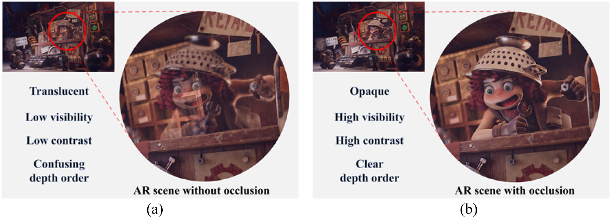
Figure 1.Simulated AR scene (a) without occlusion and (b) with occlusion by Blender. In the pictures, the merchant and store are regarded as a virtual image and a real scene, respectively. The transparency of the merchant in (a) and (b) was set to 50% and 0%, respectively, to simulate the conventional and occlusion-supported AR scene. Source image: “The Junk Shop” by Alex Treviño. Original concept by Anaïs Maamar.
The concept of the OC-OST-NED was pioneered by a few research groups [25,26]. They proposed various occlusion optics that block the light from the real objects behind the virtual images, presenting opaque virtual images to users. These occlusion optics can be classified into two categories according to the axial position of the mask blocking the real scene light. In one category, called “soft-edge masking,” the mask is in the NED plane without any imaging optics for the real scene [25,27]. The real scene light is blocked directly by the mask in the NED plane. This approach has advantages in system size and weight since it can be implemented simply by adding a masking spatial light modulator (SLM) to the world-side end of the NED. However, because the depth where the real scene is blocked (= NED plane) is largely different from the depth where the virtual image is formed (> at least tens of centimeters from the NED plane), the mask appears to be significantly blurred for the users focusing on the virtual images [25]. Although commercialized products have started to adopt this approach for its simplicity [28], it is not the ultimate solution for a realistic AR experience. To the contrary, in the other category, called “hard-edge masking,” the real scene is first imaged by optics and blocked by the mask. Although the real scene imaging optics increases the system form factor, they can place the optical position of the real scene mask at the virtual image depth, providing realistic masking of the real scene to the users without edge blurring problems [26]. As a prerequisite factor for an ideal OST-NED, various types of optics that support hard-edge occlusion masking have been proposed [29–37].
The hard-edge OC-OST-NED was first demonstrated by Kiyokawa
The OC-OST-NED supporting a varifocal hard-edge mask is becoming an emerging topic with the advance of monocular 3D display technology [38–42]. Hamasaki and Itoh [43] proposed varifocal occlusion optics using a physically shifted mask. Although they verified the 3D hard-edge occlusion mask, physically sliding the mask on an electric linear stage makes the overall system prone to issues related to mechanical movement. Rathinavel
In this paper, we propose a new optics system for the OC-OST-NED with a varifocal hard-edge mask. The proposed method supports the masking of a real scene and the imaging of the digital virtual image at variable depths using an FTL pair of opposite curvature, a single liquid crystal on silicon (LCoS) and a folding optic. The two FTLs have the opposite focal power with the same magnitude, and they enable varifocal masking and imaging while leaving the depth of the unmasked real scene not affected. The LCoS is used as both a pixelated mask for the real scene and a display for the virtual images by controlling the polarization state of the incident light. The double-pass folding optic contributes to the small form factor by minimizing the number of components.
The proposed optic places both the masking plane of the real scene and the imaging plane of the virtual images at the focal length of the FTL. Considering wide focus tunable range of currently available FTLs, the proposed varifocal optic achieves a satisfactory depth range for OC-OST-NED. To utilize a single phase-only LCoS as a mask and a display, a polarization-control method using a half-wave plate (HWP) and a linear polarizer (LP) is adopted. Since the physical locations of the mask and the image are identical, the resultant optical positions are automatically matched, spatially in a pixel-by-pixel dynamic manner, supporting the hard-edge masking naturally. The number of components required for the implementation is reduced by the polarization-based folding optics. The proposed design is, to our best knowledge, the first proposal of a compact OC-OST-NED configuration that supports varifocal imaging and hard-edge masking to the real world in front of the user without any mechanical movement.
We demonstrate the proposed method using two optical benchtop setups. In the first setup, we place two off-the-shelf liquid-based FTLs outside the folding optics to check the feasibility of our method. The continuous focal power variation of the liquid-based FTLs enables the virtual image display and real scene masking in continuous depth planes. In the second setup, a single Pancharatnam–Berry phase (PBP) type FTL that exhibits opposite focal power to different polarizations is used inside the folding optics. The polarization dependency of the PBP lens replaces two liquid-based FTLs outside the folding optics with a single PBP-type FTL inside the folding optics, improving the form factor of the system. The double-pass configuration of the folding optics also compensates the wavelength dependent focus error of the PBP lens automatically. In the following sections, we explain the principle of the proposed method and present the experimental results of the two benchtop setups.
2. PROPOSED VARIFOCAL OCCLUSION-SUPPORT SCHEME
A. Principle of the Proposed Varifocal Occlusion Optics
Figure 2 depicts a simplified scheme of the proposed varifocal occlusion optics. The proposed optical system is a relay with two FTLs, two convex lenses, and a mask. Two FTLs are placed at the front and rear focal planes of the relay and they have variable but opposite focal power, i.e., and , respectively. The two convex lenses have a fixed focal length , and the mask is located at the Fourier plane of the relay. Suppose that point sources are located at the focal length in front of the first FTL, as shown in Fig. 2(a). The light from the point sources is collimated by the first FTL of , and focused on the mask plane by the convex lens. The physical mask then blocks the light from the selected point sources. After masking, the convex lens and the second FTL of the focal length form the virtual image of the point sources at distance behind the second FTL. Note that the final virtual image distance from the second FTL (i.e., in this case) is the same as the distance of the original point sources from the first FTL. This is true not only for the point sources at distance but also for the point sources at arbitrary distance ().
![]()
Figure 2.Simplified optics of the proposed varifocal occlusion when the light source is located at (a) focal length and (b) other distance from the convex type FTL.
Figure 2(b) shows a situation when the point sources are located at an arbitrary distance () from the first FTL. The ray transfer matrix of the proposed optics is given by
Here, , , and are the propagation, lens, and identity matrix, respectively. The resultant negative identity matrix in Eq. (1) proves that the final virtual image distance from the second FTL is always the same as the original object distance from the first FTL, regardless of the variable focal length of the FTLs if the optical power of two FTLs has the same magnitude but opposite signs. This indicates that the real scene maintains its original depth after passing through the proposed optics, while the objects at the distance are selectively blocked by the mask. By changing the focal length of the FTLs, the depth of the masking plane can be controlled without introducing the depth distortion of the real scene. Note that the negative sign of the identity matrix in Eq. (1) implies that the real scene is inverted after the optics. This inversion is corrected by using additional inverting optics in the actual implementations.
The proposed optic requires two FTLs with the opposite focal power, i.e., and , respectively. This could be implemented either using two FTLs working in synchronization or using a single FTL exhibiting opposite focal power depending on the polarizations. In the following sections, we explain these two implementations.
B. Varifocal Occlusion Optics Using Two Liquid-Based FTLs
Figure 3 shows the schematic diagram of the two-FTLs based implementation of the proposed OC-OST-NED optics. As described in Fig. 3, a convex-type FTL of and a concave-type FTL of are deployed at the world-side and eye-side ends of the system, respectively. A Schmidt–Pechan prism is also employed to compensate for the real scene inversion explained in the previous section. Light from the real scene is -polarized by an LP, pre-inverted by the prism, and reflected toward the left side of the system by a polarizing beam splitter (PBS). The optics at left, indicated by a dotted rectangle in Fig. 3 are the part where the mutual occlusion and virtual scene imaging are performed. At first, a convex lens located at a focal length distance from the convex-type FTL converges the incident light from the real scene toward an LCoS that corresponds to the real scene mask in Fig. 2. The polarization angle of this light is adjusted by an HWP behind the convex lens such that the LCoS works as a per-pixel polarization modulator. The light reflected from the LCoS with the pixel-wise modulated polarization passes through the PBS again, being the intensity-modulated light. In the case of the virtual image, light emitted from the light source on the top of the left side optics in Fig. 3 is linearly polarized by an LP and reflected by the LCoS with spatially different polarizations. This polarization distribution is also transformed to the intensity distribution by passing through the PBS. Note that the real scene masking and virtual image display are performed by the single LCoS with a proper choice of the LP and the HWP angles. More details on this polarizer angle selection are explained in Section 2.D.
![]()
Figure 3.Schematic diagram of the two-FTLs optics.
The output of the optics on the left (i.e., the part in the dotted rectangle in Fig. 3) is the polarization-modulated light of the real scene and virtual images. It is first transformed to the intensity-modulated light by passing through the PBS. It then propagates toward the eye after being reflected by a mirror with a quarter-wave plate (QWP). A concave type FTL of the focal length at the eye-side finally restores the depth of the real scene, forming the mask and virtual images at distance.
Figure 4 shows the detailed light trajectory with the polarization states for the masking and nonmasking LCoS pixels in the case of a binary virtual image. When the light is incident on the nonmasking pixel, as shown in Fig. 4(a), the real scene light passes through the PBS and enters the eye pupil of the user. The virtual image light from the light source, however, is reflected by the PBS toward the world side, not reaching the eye, as depicted in Fig. 4(a). On the contrary, for the masking pixel, the real scene light is reflected from the PBS toward the world side while the virtual image light reaches the eye, as shown in Fig. 4(b). Consequently, the proposed system exhibits varifocal masking and display of the real scene and binary virtual images simultaneously. In case of the grayscale virtual images, a time-multiplexing scheme can be adopted, as will be explained in Section 2.D.
![]()
Figure 4.Schematic diagram of the two liquid-based FTL optics with light path of real objects and binary virtual image reflected on (a) a nonmasking pixel, and (b) a masking pixel of the LCoS. Blue and green lines indicate the light trajectory of real objects and virtual images, respectively.
C. Varifocal Occlusion Optics Using a Single Polarization-Dependent PBP-Type FTL
Figure 5 depicts our second OC-OST-NED optics configuration, implementable with a single FTL. In this configuration, a single polarization-dependent PBP-type FTL is placed inside the folding optics, instead of the two polarization-independent FTLs outside the folding optics in the first configuration. The PBP-type FTL exhibits positive and negative focal power depending on the incident polarization, replacing two FTLs in the first configuration.
![]()
Figure 5.Schematic diagram of a single FTL optics.
We implement the PBP-type FTL with the desired property by using a stack of multiple PBP lenses and switchable HWPs (SHWPs) [47], with two additional QWPs at the input and output ends of the device. The individual PBP lens shows the focal power of the same magnitude but opposite sign depending on the incident light polarization. By switching the SHWPs, different focal power combinations of the PBP lenses in the stack are selected, realizing the varifocal property. The maximum number of the available focal lengths is given by the square of the number of the PBP lenses in the stack. In the proposed method, however, only half is used to keep the same polarization for the input and output of the FTL. The detailed structure and the polarization changes inside the PBP-type FTL are explained in Appendix A.
D. Polarization-Control Scheme for Mutual Occlusion Optics
In the proposed scheme, a single LCoS dynamically serves for both real scene masking and virtual image display with pixel-by-pixel operation. Figure 6 shows the polarization states of the real scene and the virtual image light in the proposed configurations in Figs. 3 and 5. Note that as the optic is unfolded, a coordinate axis (i.e., the axis) is reversed after the LCoS reflection in Fig. 6. From Fig. 6 and the derivation explained in Appendix B, the Jones vectors of the output light can be obtained by
![]()
Figure 6.Polarization optics of the proposed method with light path of (a) the real object and (b) the virtual image. Red bold rectangle indicates output polarization of each case.
In Eqs. (3)–(5), and are the Jones vectors of the real object and virtual image light just before returning to the PBS, as highlighted by a red rectangle in Fig. 6, respectively. is the phase retardation of the LCoS and , are the ordinary and extraordinary refractive indices of the LC. , , and are the wavelength of the incident light, the fast axis angle of the HWP, and the transmission axis angle of the LP, respectively. The first and the second row of the , indicate the -polarized component and -polarized component, respectively. Note that the -polarized component of the , passes through the PBS and eventually reaches the user’s eye, as illustrated in Figs. 4 and 5. Thus, the second row components of the , in Eqs. (3) and (4) (i.e., and ), represent the light observed by the user’s eye.
Suppose a simple case where the light is monochromatic, and the virtual image is binary. An LCoS pixel works as a binary switch in this case. In the masking state, the real scene is blocked while the virtual image is observed, i.e., and . In the nonmasking state, the virtual image is blocked, and the real scene enters the eye, i.e., and . From Eqs. (3) and (4), it can be easily achieved by setting the HWP and LP angles to be , and controlling the LCoS phase retardation to be or for the masking and for the nonmasking, respectively. In this case, and are given by , in the masking state and and in the nonmasking state. Therefore, in the binary virtual image case, the desired operation with a 100% occlusion ratio is achieved, except for the case of (, integer).
Presenting grayscale virtual images, however, reduces the occlusion ratio of the mask. To display the grayscale images, should be in the range of [0,1], which is achievable by controlling the LCoS phase retardation in the range of [, ]. In this condition, the cannot be maintained to be 0, and some of the real scene light is leaked to be visible to the user. Figure 7 shows the visibility of the real scene and virtual image with respect to the variation of when . The varying real scene visibility according to the LCoS phase retardation in Fig. 7 implies that the occlusion ratio is reduced and dependent on the grayscale value of the virtual image.
![]()
Figure 7.Visibility of the real scene and virtual scene according to the LCoS retardation and HWP rotation angle when
To overcome this issue, we apply a time-multiplexing scheme to achieve grayscale imaging with real scene occlusion, as shown in Fig. 8. We divide a single frame into two subframes (i.e., a mask and an image subframe), and the light source for the virtual image is turned on only during the image subframe. In the mask subframe, the LCoS presents the binary mask pattern, completely blocking the real scene in the desired area. In the image subframe, the LCoS is modulated to present the grayscale virtual image. This time-multiplexing scheme increases the overall occlusion ratio and sustains the image contrast, as will be demonstrated in Section 4.B. In the actual operation, the wavelength dependency of the LCoS phase modulation also affects the occlusion performance. Further discussion on the wavelength dependency and the full-color operation is detailed in Appendix B. Also note that the time-multiplexing scheme widens the degree of freedom such that the LP angle is no longer limited to . In the following experiments, we maintain the condition of for the consistency between the binary imaging and the grayscale imaging. An exploration of the other possible choices of the LP angle is detailed in Appendix C.
![]()
Figure 8.Operation scheme of the time-multiplexed grayscale imaging.
3. HARDWARE IMPLEMENTATION
A. Verification Setup of Optical System with Two Liquid-Based FTLs
Figure 9 shows a photo of the experimental setup of two FTL optics. Two commercialized liquid-based FTLs (Optotune, EL-16-40-TC) were placed at the start and the end of the system. A Pechan prism with an LP was deployed right behind the convex-type FTL to pre-invert the real scene. A convex lens with a focal length of , a PBS, and an achromatic QWP (Edmund Optics, #46-558) were arranged on a custom mount that was fabricated using a 3D printer to minimize the air gap between the components. A zeroth-order HWP was placed on the left side of the PBS to rotate the angle of the linear polarization of the input light. A BS with 80% transmittance and 20% reflectance was used to obtain the brighter real scene than a conventional 50/50 BS. A phase-only LCoS (HOLOEYE Photonics, GAEA-2) was used to display the virtual image and to mask the real scene by modulating the polarization state of the incident light. A full-color laser (FISBA, READYBeam™) was employed as a virtual image light source of our setup. A diffusing lightguide and an LP were additionally used to achieve uniform illumination on the entire panel area of the LCoS, and to set the laser polarization, respectively. Finally, a camera (Samsung, Galaxy S21 Ultra) behind the concave-type FTL was placed at the eye position to capture the results.
![]()
Figure 9.Picture of the experiment setup of two-FTLs optics.
B. Validation Setup of Optical System with a Single PBP-Type FTL
Figure 10 shows the implementation of our second optics with a single PBP-type FTL. The left part of the setup is the same as that of the first setup shown in Fig. 9. The main changes are in the central part, highlighted by the red rectangle in Fig. 10. In this part, we replaced two commercialized liquid-based FTLs with a single homemade PBP-type FTL consisting of a PBP lens and SHWP stacks. The fabricated PBP-type FTL has two PBP lenses of and focal lengths, two SHWPs made by twisted-nematic (TN) cells, and four QWP films (Edmund Optics, WP140HE, #25-369), providing two sets of positive and negative focal lengths to the system. Here, by using the film-based QWPs, the thickness form factor of the stacked module was considerably improved. The SHWP was operated by applying a voltage to the TN cells using a two-channel function generator (GW Instek, AFG-2225). See Appendix A for the fabrication process of the FTL. The FTL was placed on a custom 3D-printed mount with an achromatic QWP. We also made a PBS mount to put two more achromatic QWPs on both sides of the PBS.
![]()
Figure 10.Experiment setup of the single FTL optics.
4. EXPERIMENT RESULTS
In this section, we show the results from two experiment setups. Sections 4.A–4.C show the results from two liquid-based FTLs optics to verify the varifocal imaging with a depth-matched mask, grayscale presentation using time-multiplexing, and full-color imaging. The result from the second experiment setup is shown in Section 4.D to demonstrate the feasibility of single PBP-type FTL optics.
A. Varifocal Occlusion
We first examined the masking performance of the proposed optics by using the binary states of the LCoS, as explained in Section 2.D. In this experiment, a real scene target is placed at 50 cm in front of the world-side FTL, and the focal power of two FTLs was set to be (diopter), presenting the virtual image and the mask on a real target plane. The result in Fig. 11 demonstrates the capability of the simultaneous imaging and masking operations using the single LCoS.
![]()
Figure 11.Captured photos of the occlusion test with/without the illumination from the fiber laser.
Second, we tested the depth-varying image and mask by changing the focal power of two FTLs. The focal length of two FTLs was set to , , , and optical infinity, such that the image and mask are formed at the corresponding distances, i.e., 33, 50, 100 cm, and optical infinity, respectively. The real scene target was placed at a distance of 50 cm (= 2D), as in the previous experiment in Fig. 11.
Figure 12 shows the experiment results of the varifocal imaging and occlusion test. In Fig. 12, it can be observed that the virtual image is focused and blurred according to the camera focus at each image distance, which indicates the successful presentation of the varifocal images. Note that when the camera focus is at the real object distance (i.e., a distance of 50 cm, as in the third row in Fig. 12), the real object maintains its focus regardless of the focal power variation of the two FTLs. This demonstrates that the proposed optics changes the virtual image and the mask distance without distorting the real scene depth, as we explained in Section 2.A. Also note that the depth of the virtual scene image and the real scene mask does not need to be selected from a pre-determined discrete set but can be controlled continuously within a wide range, owing to the continuous focal power variation of the liquid-type FTLs used in our implementation.
![]()
Figure 12.Captured photos of the real scene at 50 cm (= 2D) while the virtual image is at 33, 50, 100 cm, and optical infinity.
B. Grayscale Imaging Using Temporal Multiplexing
Figure 13 shows the experiment result of the grayscale imaging with the varifocal hard-edge mask scheme. A virtual dinosaur image was displayed at the optical infinity. The real scene consists of a target object at 50 cm and a white background at the optical infinity. The virtual dinosaur image at the optical infinity was pre-cropped to account for its occlusion by the real target object at 50 cm. To represent the dinosaur in grayscale, we use the time-multiplexing scheme explained in Section 2.D. The first and second columns in Fig. 13 show the observed images in the mask subframe and image subframe without a virtual image light source, respectively. In the mask subframe, the pixel values of the LCoS were set to achieve the maximum occlusion. The result in the first column of Fig. 13 demonstrates the proper occlusion of the real white background as expected. In the image subframe, the LCoS displays the virtual dinosaur image. As the pixel values of the LCoS pattern in this subframe are determined to present the grayscale virtual image, the occlusion of the real scene becomes nonuniform, being slightly degraded. However, by temporal multiplexing of the mask and the image subframe, the overall occlusion still maintains a satisfactory level, as shown in the third column of Fig. 13. Finally, by turning on the virtual image light source in the image subframe, the grayscale virtual dinosaur was displayed with high quality, as in the last column in Fig. 13.
![]()
Figure 13.Time-multiplexed experimental result for grayscale imaging. In the time multiplexing, the mask and image subframes are alternately displayed at 10 Hz. The pictures were taken with a camera setting of ISO 50 and a 1 s shutter speed.
The experiment results of the grayscale imaging with more complex real scenes at different depths are presented in Fig. 14. Two real targets, a yellow fish and a background ocean with an orange fish, were placed at 25 cm and 50 cm in front of the system, respectively. A virtual image (i.e., a green fish) was displayed at a distance of 33 cm. As before, the virtual green fish image at 33 cm was pre-cropped to mimic its occlusion by the real yellow fish at 25 cm. The result in Fig. 14 reveals that the virtual green fish image occludes the real orange fish and the ocean behind it, enabling clear depth perception between the virtual image and the real targets.
![]()
Figure 14.Experiment result of the grayscale imaging with the time-multiplexing scheme. The real target of the yellow fish and the background is located at 25 cm and 50 cm while the virtual images are at 33 cm.
Figure 15 highlights the effect of the occlusion for an AR scene that consists of a real background (“beach”) and a virtual image (“dinosaur”). The result in Fig. 15 clearly shows that the occlusion-supported image of the proposed system effectively portrays a realistic AR scene, while the conventional simply merged image without the occlusion shows low visibility and contrast. Note that the luminance of the virtual image was set to be the same in both cases, and the enhanced visibility and contrast in Fig. 15 are solely because of the occlusion enabled by the proposed method.
![]()
Figure 15.Comparison of the AR scene with occlusion and without occlusion. Both pictures were taken with the same camera setting of ISO 50 and a 1 s shutter speed.
C. Full-Color Grayscale Imaging
Figure 16 shows the full-color imaging result. The proposed method achieves the masking and display by giving pixel-wise phase retardation to the incident light. Since the amount of the phase retardation for a given LCoS pixel voltage is dependent on the wavelength of the incident light, the display pattern of the LCoS was optimized for R, G, and B color separately for full-color imaging.
![]()
Figure 16.Experiment results of the full-color imaging. The real target of the satellite and background is placed at 30 cm and 150 cm while the virtual image of the spaceman is at 70 cm. Camera setting: ISO 50 and 2 s shutter speed.
The result is shown in Fig. 16. The real target (“satellite”) and background (“space”) were placed at a distance of 30 cm and 1.5 m, respectively, as presented in the first row of Fig. 16. The virtual image (“spaceman”) with the corresponding mask was displayed at 70 cm, between the “satellite” and “space.” The virtual “spaceman” image at the middle-depth plane was pre-cropped again, considering the “satellite” real object in the near-depth plane. As evident from Fig. 16, the full-color virtual image display with adequate occlusion of the real scene can be obtained by the proposed method. Note that for full-color image presentation, the time-multiplexing scheme in Section 2.D was employed to display grayscale images of the RGB color channels sequentially. The camera captured the full sequence of the RGB grayscale image subframes and mask subframes in a single shot with a setting of ISO 50 and a 2 s shutter speed. Also note that the RGB image subframes were obtained only by adjusting the voltage levels applied to LCoS pixels, leaving the HWP and the LP angles unchanged. Therefore, the real-time full-color imaging with a varifocal hard-edge mask would be enabled by utilizing the phase-only LCoS with a fast refresh rate.
D. Experiment Results Using the Optical System with a Single PBP-Type FTL
The demonstrations in the previous section can also be realized by using only a single PBP-type FTL module instead of two liquid-type FTLs. We placed a real target at 50 cm and captured the result using an optical benchtop setup in Fig. 10. As mentioned in Section 3.B, our homemade PBP-type FTL has two PBP lenses with focal lengths of and , which would result in two focal lengths of 0.41 m and 2.38 m if all elements are cemented without a gap. In the implementation of the device, the air gap between the PBP lenses shifts the focal lengths slightly, achieving 0.45 m and 2.3 m in experiment.
Figure 17 shows the experimental results. The virtual image with a hard-edge mask was displayed at varying depths successfully using only the single PBP-type FTL, yielding results equivalent to the previous two-FTLs setup. Note that the depth and size of the real target also remained still regardless of the focal power of the PBP-type FTL, proving the distortion-free see-through view of the proposed configuration. Also note that the color aberration of the real scene caused by the wavelength-dependent focal power of a usual PBP lens-based optics is not present in the proposed optics because the color aberration in the forward pass through the PBP lens in the FTL is automatically compensated in the backward pass of the same PBP lens in the proposed optics.
![]()
Figure 17.Feasibility test of varifocal occlusion using a single PBP-type FTL.
Figure 18 shows the experiment results of displaying the grayscale image. As before, the time-multiplexing technique was applied to represent the grayscale of the image while preserving reasonable occlusion. The captured photos in Fig. 18 show the AR scene with a grayscale virtual image (bird) that occludes the real background (beach). These results confirm the proper occlusion of the real background and high-quality display of the virtual image similar to the results from two-FTL-based implementation, proving the validity of the proposed method with a single FTL.
![]()
Figure 18.Grayscale image presentation using a single PBP-type FTL setup (
5. DISCUSSION
Varifocal occlusion-support AR image presentation of the proposed single LCoS based OC-OST-NED system was successfully demonstrated using both a liquid-type FTL pair configuration and a single PBP-type FTL configuration. We believe that the current implementation can be further improved.
In the presented implementation, the refresh rate of the grayscale imaging was 10 Hz, which is lower than 60 Hz of standard displays. The low-speed imaging stems from the limited operation speed of the LCoS in the Python-based driving mode that was used to synchronize the LCoS and the laser light source. We believe that grayscale imaging with a higher refresh rate can be achieved by adopting faster LCoS or implementing a more sophisticated synchronization method.
The FoV of our implementation is approximately 2.45° in the diagonal direction. Three factors limit the FoV of our setup: the small ray angle tolerance of the Pechan prism, the small size of the LCoS panel, and the long focal length of the convex lens. The Pechan prism can be removed by adding a convex lens between the PBS and mirror, forming another optics to invert the real scene. The focal length of the convex lens on the left part of the optics can be shortened by substituting the 80/20 BS with a light source to a waveguide-based backlight [41]. By adopting the waveguide-type backlight and a shorter-focal-length convex lens, the distance between the LCoS and the convex lens can be significantly reduced, achieving a wider FoV. For instance, suppose that a 25 mm aperture optic without the Pechan prism and a convex lens of 30 mm are implemented with a 1 mm thickness waveguide-type backlight. We estimate that the maximum diagonal FoV of 33.01° can be achieved with the current 0.7” LCoS panel by shortening the gap between the convex lens and the LCoS from 100 mm to 30 mm. To expand the FoV further, enlarging the LCoS panel size is required. We expect that the size of the LCoS will be increased considering the rapid advance of the manufacturing technology [23], potentially allowing further expansion of the FoV in the proposed method.
The dimensions of each system are approximately () in the two-FTL setup and in the single FTL setup, provided that the circuit board size of the LCoS is disregarded. A more compact system can be achieved by shortening the long focal length of the convex lens. Assuming that the waveguide-based backlight is adopted, and the Pechan prism is replaced by another system as explained above, the convex lens of 30 mm focal length can be adopted. With these assumptions, the size of both systems can be optimized to , and , respectively. Note that the optimized dimension was calculated using the 25 mm aperture optic. If the lens diameter and the PBS size are reduced (e.g., 10 mm), the system form factor can be reduced further with the sacrifice of the FoV. Replacing the PBS combiner with a more compact combiner can be also considered to reduce the system size and enhance the integration with commercialized devices. Given that the commercialized AR NEDs mainly use compact waveguide combiners, our method could be integrated into contemporary AR NEDs by substituting the PBS with the waveguide combiner equipped with achromatic couplers. However, the implementation with a minimized system form factor is out of the scope of this paper and we will leave it for future work.
In the current implementation, the available depth planes of the virtual images in the single PBP-type FTL setup are limited to two, insufficient for exhibiting an immersive 3D experience. Assuming additional stacks of the PBP lens and TN cell are incorporated into the current PBP-type FTL, the number of the depth planes would increase, enabling the expression of a 3D scene with higher depth resolution. In this paper, we focus on confirming the principle and feasibility of the implementation using the PBP-type FTL. We will leave the depth range extension of the single PBP-type FTL setup as a topic for future work.
The full-color image representation was only demonstrated using the two-FTL setup. In the single FTL implementation, the fabricated PBP lens is optimized to green color, evoking chromatic aberration, and hindering the full-color imaging. Although the chromatic aberration of the PBP-type FTL in a real scene path is self-compensated by the double-pass folding structure as explained in Appendix A, the chromatic aberration of the virtual images that experience only a single pass is not compensated. Given that the recent work by Luo
In the case of the two-FTLs implementation, the depth of the real scene is slightly shifted in the axial direction by the amount of the gap between two FTLs. However, this discrepancy is small because the folding optics adopted in our configuration lessens a physical gap between the convex type FTL and the concave type FTL. We expect the amount of axial shift could be smaller than 5 cm by detaching the optical components from the mount and reducing the air gap between them. Note that the single PBP-type FTL implementation shows no axial shift from the varifocal optics since the physical gap between two FTLs is zero.
Finally, compared to the varifocal occlusion results with the two-FTLs based OC-OST-NED, image degradation with blurring is observed (Figs. 17 and 18) in the single PBP-type FTL scheme, which needs to be improved. Unlike the two-FTLs optics operated by the polarization-insensitive focus-tuning liquid lens units (Figs. 3 and 9), the PBP-based single FTL scheme can provide a much-improved form factor by using the polarization-dependent bifocal switching and polarization-changing abilities of the PBP lens. But precise control on each polarization-changing step between the polarization-dependent units is essential for better pixel-wise control of the varifocal self-aligned mutual occlusion effects, as explained in detail in Appendix A. In the implementation of the compact bi-stack module for the single FTL optics, four layers of the film-based achromatic QWPs were additionally used, compared to the two-FTLs optics, which can be ascribed to the image degradation caused by the generation of multiple surface-reflective stray rays and distortions in the polarization state. The bulk optics of QWP used in both experiment schemes exhibits superior anti-reflection characteristics of less than 1% in surface reflection. In contrast, the employed film-type QWPs have surface reflection properties at approximately 10% while generating haze. Furthermore, the film-type achromatic QWP exhibits relatively high chromatic dispersion characteristics, leading to polarization control distortions deviating from the ideal QWP behavior. However, we expect that a significant improvement in image qualities in both real and AR scenes is achievable by adopting superior achromatic film-type QWPs with anti-reflection coatings over the whole visible range.
6. CONCLUSION
In this paper, we proposed an OC-OST-NED that supports virtual scene imaging and real scene masking at variable depths by using a single phase-only LCoS and varifocal optics. The opposite curvature FTL pair of the proposed varifocal occlusion optics enables the optical relay of the real scene without depth aberration and the display of the virtual image with the corresponding mask in the wide depth range required for the NED applications. The single LCoS of the proposed optics works both for the virtual image display and real scene masking, enabling self-alignment of the image and mask. The double-pass folding configuration reduces the form factor of the proposed system. The feasibility of the proposed system was verified using two optical implementations: one with two commercialized liquid-type FTLs outside the folding optics and the other one with a single homemade PBP-type FTL inside the folding optics. Both implementations demonstrated that grayscale virtual images can be displayed in a wide depth range with proper occlusion of the real scene.
Acknowledgment
Acknowledgment. This research was partly financially supported by the National Research Foundation of Korea (NRF) grant funded by the Korea Government (MSIT) (Research on occlusion-capable holographic augmented reality 3D near-eye display, 30%), Institute of Civil Military Technology Cooperation funded by the Defense Acquisition Program Administration and Ministry of Trade, Industry and Energy of the Korean government (Technical development of simultaneous acquisition of 2D/3D information based on fast-switching microlens array applicable to unmanned aerial vehicle, 50%), Culture, Sports and Tourism R&D Program through the Korea Creative Content Agency grant funded by the Ministry of Culture, Sports and Tourism in 2022 (Project Name: Development of immersive contents anti-counterfeiting and holography technology with micro patterning, 10%), and Institute of Information & Communications Technology Planning & Evaluation (IITP) grant funded by the Korea government (MSIT) (Development of digital hologram window reconstruction, 10%).
APPENDIX A: FABRICATION, STRUCTURE, AND POLARIZATION VARIATION OF PBP-TYPE Ftls
The fabrication process of the PBP lens used in this study is shown in Fig.
![]()
Figure 19.(a) Fabrication process of the PBP lens and (b) phase profiles of the PBP lens with the polarization-dependent focal lengths of
![]()
Figure 20.(a) and (b) The polarization-dependent focusing (
![]()
Figure 21.Polarization change schemes of real scenes and virtual AR images for varifocal self-aligned mutual occlusion effects constructed by the PBP-type FTL module, where two PBP-type FTLs are cascaded and their incident polarization states are controlled by the LC-based SHWP1 and SHWP2 cells for (a) the near-depth and (b) far-depth AR imaging switching with pixelized occlusions.
APPENDIX B: ANALYSIS OF POLARIZATION-BASED OCCLUSION USING THE JONES MATRIX
Figure
![]()
Figure 22.Unfolded optics of polarization-based occlusion. Bold orange arrow in the LCoS indicates the direction of the LCs aligned in parallel and an
![]()
Figure 23.Visibility of the real scene and the virtual scene when the incident light is monochromatic.
![]()
Figure 24.Visibility of the real scene in the full-color spectrum when the phase retardation of the LCoS is optimized to each RGB color.
![]()
Figure 25.Average visibility of the real scene over the full-color range when the phase retardation of the LCoS is optimized to wavelengths of (a) 450 nm, (b) 520 nm, and (c) 638 nm. The vertical bars indicate the variance of the real scene visibility over the full-color range at each HWP rotation angle.
APPENDIX C: MODIFIED OPERATION SCHEME BASED ON THE POLARIZATION CHANGE OF THE VIRTUAL IMAGE LIGHT SOURCE
Up to now, the LP angle for the virtual image light source was set to be twice that of the HWP angle with a negative sign, i.e., . In this appendix, we discuss another possible choice of the LP angle and the resultant modification of the time-multiplexed operation scheme. The equations in Section
From Eqs. (
![]()
Figure 26.Visibility of the real scene and virtual scene according to the LCoS retardation and HWP rotation angle when
Note that this new characteristic can be beneficial when the brightness of the real scene is much higher than the virtual light source. Due to the time multiplexing in the grayscale virtual image case, some of the real scene light is not completely occluded in the image subframe but is leaked into the observed virtual image, degrading the contrast. In the original condition , this leakage is stronger in the dark virtual image area, affecting the virtual image contrast more, while it is stronger in the bright virtual image area in the new condition , affecting the contrast less. An experimental demonstration of the enhanced contrast under highly bright real scene condition using the new choice is given in Appendix
APPENDIX D: MEASUREMENT OF THE OCCLUSION AND CONTRAST
We measured the occlusion ratio of the occlusion mask as well as the contrast ratio of the virtual image. In the measuring process, we used a two liquid-based FTLs implementation with a CMOS camera (BFS-PGE-200S6-C, FLIR) for accurate measurement of the occlusion performance.
Figure
![]()
Figure 27.(a) Experimental setup for measuring the occlusion ratio. (b) Captured result and ROI used to calculate the occlusion ratio of the masking pixel. (c) Intensity distribution of the center line in the ROI indicated as a yellow line.
![]()
Figure 28.Experimental result of the contrast measurement under moderate real background luminance when
![]()
Figure 29.Experimental result of the contrast measurement under strong real background luminance when
References
[22] J. E. Cutting, P. M. Vishton. Perceiving layout and knowing distances: the integration, relative potency, and contextual use of different information about depth. Perception of Space and Motion, 69-117(1995).
[24] B. C. Kress. Optical Architectures for Augmented-, Virtual-, and Mixed-Reality Headsets(2020).
[26] K. Kiyokawa, M. Billinghurst, B. Campbell. An occlusion capable optical see-through head mount display for supporting co-located collaboration. 2nd IEEE and ACM International Symposium on Mixed and Augmented Reality, 1-9(2003).
[28] V. Mathur, J. N. Haddock, T. Diehl. Ambient light management systems and methods for wearable devices. U.S. Patent(2023).
[32] O. Cakmakci, Y. Ha, J. P. Rolland. A compact optical see-through head-worn display with occlusion support. Proceedings of the Third IEEE and ACM International Symposium on Mixed and Augmented Reality (ISMAR), 16-25(2004).
[33] C. Gao, Y. Lin, H. Hua. Occlusion capable optical see-through head-mounted display using freeform optics. IEEE International Symposium on Mixed and Augmented Reality (ISMAR), 281-282(2012).
[39] S. Lee, Y. Jo, D. Yoo. Tomographic near-eye displays. Nat. Commun., 10, 2497(2019).
[41] J. Kim, M. Gopakumar, S. Choi. Holographic glasses for virtual reality. ACM SIGGRAPH 2022 Conference Proceedings, 33(2022).
[42] D. Lanman, D. Luebke. Near-eye light field displays. ACM Trans. Graph., 32, 220(2013).
[45] Y. Hiroi, T. Kaminokado, S. Ono. Focal surface occlusion. Opt. Express, 29, 36581-36597(2021).
[47] L. Lu, S. C. McEldowney, P. Saarikko. Focus adjusting Pancharatnam Berry phase liquid crystal lenses in a head-mounted display. U.S. Patent(2019).

Set citation alerts for the article
Please enter your email address
© Copyright 2018-2021 | Chinese Laser Press. All Rights Reserved 沪ICP备15018463号-20