• Infrared and Laser Engineering
  • Vol. 50, Issue 6, 20200403 (2021)
Ruiwen Geng1, Qiming Xie2、*, Wanqing Zhang2, Jie Kang2, Yueqing Liang2, Xiaojing Yang1, and Rui Li3
Author Affiliations
  • 1Faculty of Mechanical and Electrical Engineering, Kunming University of Science and Technology, Kunming 650500, China
  • 2Kunming Institute of Physics, Kunming 650233, China
  • 3Faculty of Environmental Science and Engineering, Kunming University of Science and Technology, Kunming 650500, China
  • show less
    DOI: 10.3788/IRLA20200403 Cite this Article
    Ruiwen Geng, Qiming Xie, Wanqing Zhang, Jie Kang, Yueqing Liang, Xiaojing Yang, Rui Li. Study on the material removal mechanism of ZnSe crystal via ultra-precision diamond turning[J]. Infrared and Laser Engineering, 2021, 50(6): 20200403 Copy Citation Text show less
    Experimental step-ups and schematic of cutting experiments. (a) the ultra-precion lathe; (b) enlarged view of workpiece; (c) the machined groove of plunge-cutting test; (d) schematic of machined surface for face-turning test
    Fig. 1. Experimental step-ups and schematic of cutting experiments. (a) the ultra-precion lathe; (b) enlarged view of workpiece; (c) the machined groove of plunge-cutting test; (d) schematic of machined surface for face-turning test
    Typical FESEM image of ZnSe crystal machined groove by using. (a) tool I with 0° rank angle; (b) tool II with −25° rank angle; (c) Enlarged region I; (d) Enlarged region II
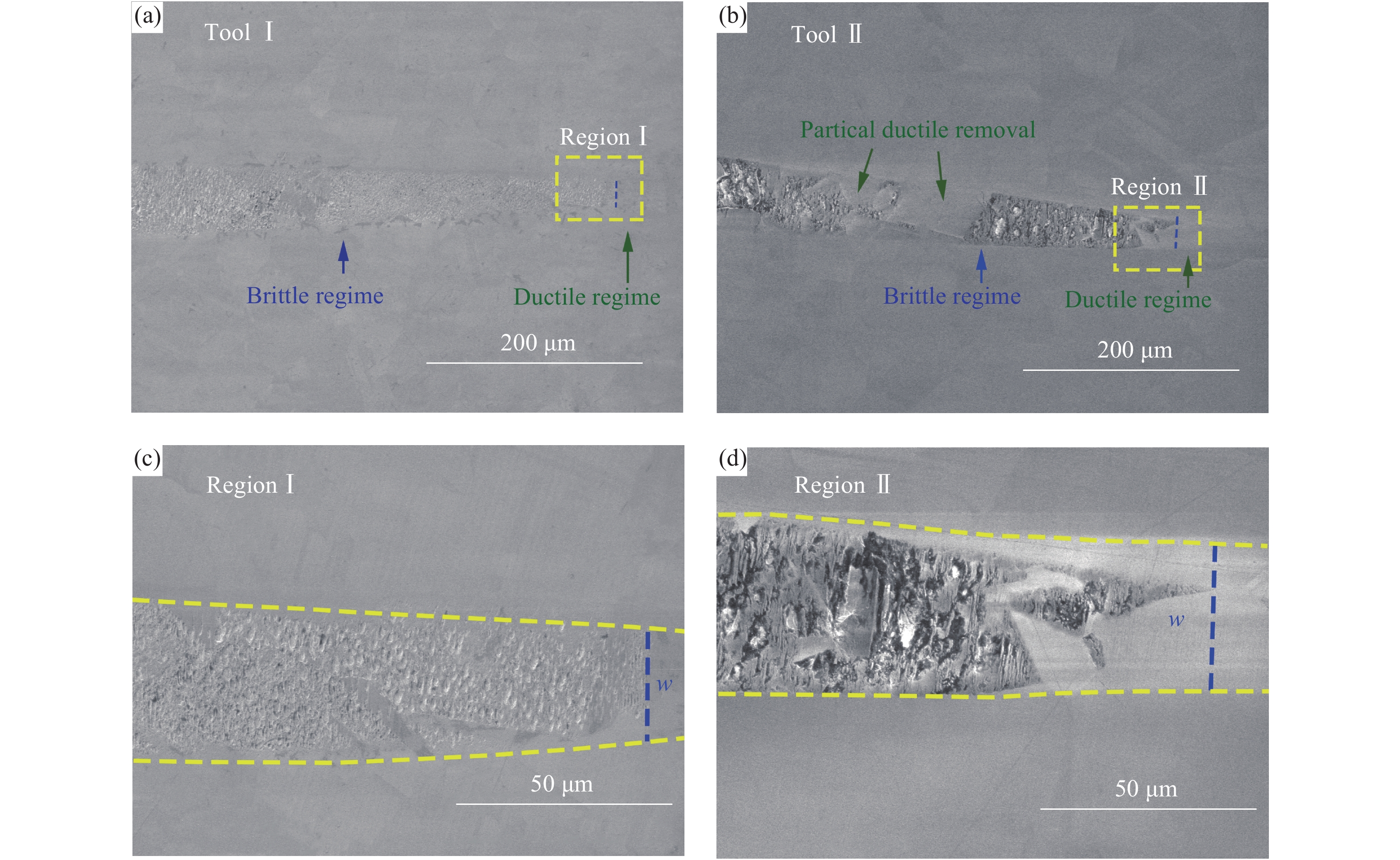
    Fig. 2. Typical FESEM image of ZnSe crystal machined groove by using. (a) tool I with 0° rank angle; (b) tool II with −25° rank angle; (c) Enlarged region I; (d) Enlarged region II
    Ductile-brittle transition depth by using tool I and tool II
    Fig. 3. Ductile-brittle transition depth by using tool I and tool II
    Schematic of the tool-workpiece contract in ultra-precision machining
    Fig. 4. Schematic of the tool-workpiece contract in ultra-precision machining
    2D counter plot of hmax vs depth of cut and feed rate
    Fig. 5. 2D counter plot of hmax vs depth of cut and feed rate
    FESEM image of surface morphology under different feed rates. (a) 2 μm/rev; (b) 1.5 μm/rev; (c) 1 μm/rev; (d) 0.5 μm/rev
    Fig. 6. FESEM image of surface morphology under different feed rates. (a) 2 μm/rev; (b) 1.5 μm/rev; (c) 1 μm/rev; (d) 0.5 μm/rev
    Mechanism of surface damage formation: (a) Step-liked cracks; (b) Micro-pits
    Fig. 7. Mechanism of surface damage formation: (a) Step-liked cracks; (b) Micro-pits
    3D surface morphany at different feed rates. (a) 2 μm/rev; (b) 1.5 μm/rev; (c) 1 μm/rev; (d) 0.5 μm/rev
    Fig. 8. 3D surface morphany at different feed rates. (a) 2 μm/rev; (b) 1.5 μm/rev; (c) 1 μm/rev; (d) 0.5 μm/rev
    Surface roughness under different feed rates
    Fig. 9. Surface roughness under different feed rates
    Raman spectra of the machined surface under different feed rates
    Fig. 10. Raman spectra of the machined surface under different feed rates
    Raman spectra of the chips under different feed rates
    Fig. 11. Raman spectra of the chips under different feed rates
    MaterialZnSe
    Grain size (typical) /μm70
    Yang’s modulus /GPa79
    Hardness /GPa1.2
    Fracture toughness/MPa·m0.50.9
    Poisson ratio0.28
    Density /g·cm−35.3
    Table 1. Material properties of ZnSe crystal[21]
    No.ParametersValues
    1Nose radius/mm1.15 (tool Ⅰ), 1.12 (tool Ⅱ)
    2Rank angle/(°)−25 (tool Ⅰ), 0 (tool Ⅱ)
    3Clearance angle/(°)10 (tool Ⅰ, Ⅱ)
    4Clearance angle/(°)10 (tool Ⅰ, Ⅱ)
    5Cutting speed/m·s−18.3×10−3 (PCT), 2.88 (FTT)
    6Depth of cut/μm0-2 (PCT), 3 (FTT)
    7Feed rate/μm·rev−10.5, 1, 1.5 and 2 (FTT)
    Table 2. Cutting tool parameters and experimental condition
    Ruiwen Geng, Qiming Xie, Wanqing Zhang, Jie Kang, Yueqing Liang, Xiaojing Yang, Rui Li. Study on the material removal mechanism of ZnSe crystal via ultra-precision diamond turning[J]. Infrared and Laser Engineering, 2021, 50(6): 20200403
    Download Citation