
Dongsheng Yang, Shusheng Bi, Yueri Cai, Chang Yuan. Wide-Area Monocular Plane Measurement Based on Calibration on a Parallel Plane Using Multiple Targets[J]. Acta Optica Sinica, 2017, 37(10): 1015001
- Acta Optica Sinica
- Vol. 37, Issue 10, 1015001 (2017)
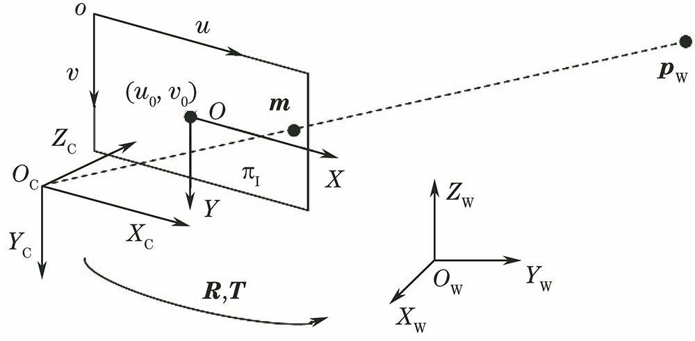
Fig. 1. Camera model
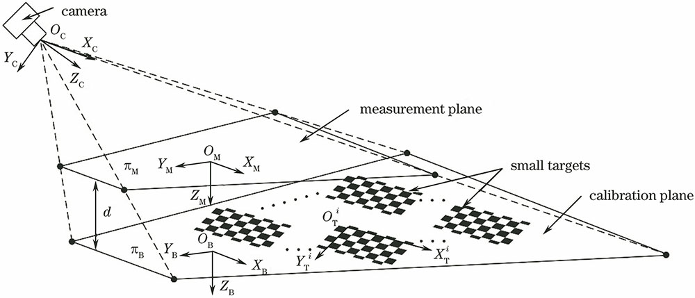
Fig. 2. Schematic of calibration principle
Fig. 3. Geometrical relationship of plane measurement
Fig. 4. (a) Distribution of measurement precision of different positions in the measuring area; (b) distribution of measurement precision versus xM, when yM=-500 mm; (c) distribution of measurement precision versus yM, when xM=0 mm
Fig. 5. Measurement precision versus camera angles
Fig. 6. Experimental setup
Fig. 7. Target images. (a) First group; (b) second group
Fig. 8. Schematic of precision measurement experiment. (a) Measuring planes; (b) positions of small targets; (c) feature point intervals of a small target
Fig. 9. Measurement error of different positions on 0 mm plane. (a) Absolute error; (b) relative error
Fig. 10. Measurement error of different positions on 100 mm plane. (a) Absolute error; (b) relative error
Fig. 11. Measurement error of different positions on 200 mm plane. (a) Absolute error; (b) relative error
Fig. 12. Relationship between total measurement error and distance of different planes using multi-target method. (a) Absolute error; (b) relative error
Fig. 13. Measurement error distribution of different planes using multi-target method. (a) Absolute error; (b) relative error
Fig. 14. Error of XM and YM axes in different positions on the 50 mm plane. (a) Absolute error; (b) relative error
|
Table 1. Parameters for precision analysis
|
Table 2. Calibration results

Set citation alerts for the article
Please enter your email address
© Copyright 2018-2021 | Chinese Laser Press. All Rights Reserved 沪ICP备15018463号-20