José A. Rodrigo, Mercedes Angulo, Tatiana Alieva, "All-optical motion control of metal nanoparticles powered by propulsion forces tailored in 3D trajectories," Photonics Res. 9, 1 (2021)
Copy Citation Text
Increasing interest has been drawn to optical manipulation of metal (plasmonic) nanoparticles due to their unique response on electromagnetic radiation, prompting numerous applications in nanofabrication, photonics, sensing, etc. The familiar point-like laser tweezers rely on the exclusive use of optical confinement forces that allow stable trapping of a single metal nanoparticle in 3D. Simultaneous all-optical (contactless) confinement and motion control of single and multiple metal nanoparticles is one of the major challenges to be overcome. This article reports and provides guidance on mastering a sophisticated manipulation technique harnessing confinement and propulsion forces, enabling simultaneous all-optical confinement and motion control of nanoparticles along 3D trajectories. As an example, for the first time to our knowledge, programmable transport of gold and silver nanospheres with a radius of 50 and 30 nm, respectively, along 3D trajectories tailored on demand, is experimentally demonstrated. It has been achieved by an independent design of both types of optical forces in a single-beam laser trap in the form of a reconfigurable 3D curve. The controlled motion of multiple nanoparticles, far away from chamber walls, allows studying induced electrodynamic interactions between them, such as plasmonic coupling, observed in the presented experiments. The independent control of optical confinement and propulsion forces provides enhanced flexibility to manipulate matter with light, paving the way to new applications involving the formation, sorting, delivery, and assembling of nanostructures.
1. INTRODUCTION
Optical trapping of nanoparticles (further referred to as NPs) is an active research field driven by the need to achieve precise manipulation and versatile control of nanostructures [1–5]. In this context, it is crucial to investigate the physics of single or multiple particle interaction with light without any interfering substrate. Such studies require all-optical manipulation tools provided by a three-dimensional (3D) optical trap. In the current state of the art, 3D trapping of NPs has been only achieved by using the well-known optical tweezers (a point-like laser trap) [6–10]. The trapping arises from an optical force proportional to the intensity gradient of a laser beam strongly focused by using a high numerical aperture () microscope objective lens. This intensity-gradient force scales with the particle polarizability [1,2]. For stable 3D optical trapping, the intensity-gradient force must overcome the light’s radiation pressure, arising from scattering and absorption, and pointing in the beam propagation direction.
For practical applications, the metal NPs (silver and gold, among others) are of the most interest [1–3]. Metal NPs have significantly higher polarizability and offer improved trapping stability compared to dielectric NPs [7–9]. The 3D trapping of Rayleigh gold NPs, whose dimensions are significantly smaller than the trapping wavelength (e.g., with being the radius of a spherical particle), was reported for the first time by Svoboda et al. [7]. In particular, it has been shown that the trapping efficiency of a Rayleigh gold NP is 7 times better than that of a similar-sized dielectric particle [7]. An NP with plasmon resonance near the trapping laser wavelength is released from the trap due to optothermal escape forces caused by the enhanced heating of the particle [7–9]. Thus, a trapping laser beam with off-resonant wavelength is one condition for stable 3D optical trapping of a metal NP [7–9]. Note that metal NPs exhibit plasmonic resonances tuned by the particle’s size and shape [1,11], as well as by the surrounding medium (e.g., an aqueous solution).
Another crucial condition for stable 3D trapping of an NP is to minimize the spherical aberration in the trapping laser beam, which can significantly degrade the axial trapping strength. This can be achieved by using a microscope’s immersion oil of high refractive index (e.g., ) that allows obtaining axial trapping strength improved to a factor at a trapping depth of about 5–10 μm [8]. The enhanced trapping efficiency also implies significantly less optical heating of the particles because less laser power is required [8]. Stable 3D optical trapping of metal NPs has been characterized by studying the scaling of trapping strength with the particle size (in Rayleigh regime), with the example of gold nanospheres of radius 5–50 nm [7–9] and silver nanospheres of radius 20 nm [10].
Sign up for Photonics Research TOC. Get the latest issue of Photonics Research delivered right to you!Sign up now
Optical trapping of multiple metal NPs has also been investigated by using a point-like trap. It has been shown that the trapping stability is influenced by the time evolution of the coupled plasmon resonance of the NPs [10]. Specifically, the trapped metal NPs (silver spheres, 20 nm radius) display a gradual redshift of the coupled plasmon resonance because with time more particles are trapped, reducing the interparticle separation distances [10]. Such plasmonic coupling dynamics exhibited by confined metal NPs has been studied by using dark-field imaging and spectroscopy in several works [10,12,13]. When the coupled plasmon becomes resonant with the trapping laser wavelength, the NPs are released from the trap due to optothermal escape forces caused by the plasmonic-enhanced heating (strong light absorption) [10].
An NP confined by optical tweezers can be moved by shifting the trapping beam. In the case of a Rayleigh NP, the effects of the optical confinement force are separated from the action of the optical propulsion force arising from transverse phase gradients [14,15], which can be tailored in structured trapping beams (e.g., in the form of a curve) [15,16]. For Rayleigh NPs, the confinement force is proportional to the real part of the particle polarizability, whereas the propulsion force is proportional to its imaginary part [3,17]. A proper design of the optical propulsion force allows driving the NP motion without the need to shift the trapping beam.
A laser trap providing simultaneous optical confinement and transport of NPs is of high interest. Recent works have shown that the transverse phase-gradient propulsion force of a structured trapping beam can be applied for transport of metal NPs in 2D by using an optical vortex trap [18–21] or an optical trap in the form of an arbitrary 2D curve providing robotic motion planning [22]. Interesting electrodynamic interactions between the transported NPs have been observed apart from plasmonic coupling [18,19,21]. In particular, it has been found that interacting pairs of identical silver NPs (homodimer of two NPs, 75 nm radius each) experience a net driving force modulated by a separation-dependent interference effect arising from optical binding for a small phase-gradient propulsion force [21]. For large transverse phase gradients, the symmetry of the interaction between the particles is broken, and the distances at which optical binding [23] occurs change. Therefore, the tuning of the phase gradient of the trapping laser beam can also be applied to enhance the versatility of optical binding as a tool for particle assembly and formation of optical matter arrays [21]. Let us underline that the previously reported studies [18–22,24–27] have been limited to 2D particle motion in contact with a surface (the coverslip) in order to provide the axial particle confinement.
Here, for the first time, we experimentally demonstrate that all-optical confinement and motion control of metal Rayleigh NPs is possible, using the example of programmable transport along 3D trajectories on demand. This has been achieved by using a single-beam trap in the form of a diffraction-limited curve (a freestyle laser trap) that combines a high-intensity-gradient confinement force and a propulsion phase-gradient force independently prescribed along an arbitrary curve [16,28]. We have used an off-resonant trapping wavelength of 1064 nm to manipulate gold and silver nanospheres with a radius of 50 and 30 nm, respectively. The optical transport of these metal NPs is demonstrated at a trapping depth of μ, far away from the chamber walls (e.g., microscope’s coverslip glass), avoiding any interfering substrate effects. Different configurations of the driving optical force are studied to transport single and multiple metal NPs. Plasmonic coupling between the transported NPs is revealed by the observed color-change dynamics in the scattered light analyzed by using dark-field imaging.
The article is organized as follows. In Section 2, we summarize the fundamentals underlying the optical manipulation of NPs achieved by using the freestyle laser trap and describe its experimental implementation. The experimental results are presented and discussed in Section 3. Finally, concluding remarks and future perspectives are discussed.
2. FUNDAMENTALS
A. Optical Manipulation of NPs
Here, we consider all-optical manipulation of colloidal NPs to achieve their 3D confinement and transport along arbitrary curved trajectories. Thus, the optical forces exerted on the NP have been properly designed according to the desired trajectory and velocity of the particle transport. In the dipole approximation, the time-averaged force induced by a monochromatic optical field is given by [3,17,29] where is an electric field vector with components and the gradient operator is expressed in the chosen coordinate system, with being a placeholder for the spatial coordinates. Note that is the permittivity of vacuum, is the relative permittivity of the surrounding medium (often assumed as a real parameter), and is the particle polarizability. The expression Eq. (1) corresponds to the electric dipole force valid for a Rayleigh particle with radius of , with and being the light’s wavelength and wave vector in the medium, respectively. Note that the magnetic response of metal (gold and silver) Rayleigh NPs is negligible at optical frequencies [30], and this leaves us only with the electric field contribution. The NPs considered in our study satisfy this condition: , , and .
The first term in Eq. (1) can be rewritten as , where is the irradiance (intensity) of the incident wave in the medium and is the speed of light in vacuum. Depending on the sign of the real part of polarizability, , this intensity-gradient force pulls the particle toward the position of the intensity maximum or minimum . Here, we will consider the case that corresponds to our experimental conditions. The second term, determined by phase gradients of the field components, arises from the light absorption and scattering by the particle, and further, it will be referred to as radiation force, . It depends on the imaginary part of the polarizability , which is always positive and can be expressed as . Note that , , and are the particle cross sections for extinction, absorption, and scattering, correspondingly. The extinction cross section depends on the relative permittivity (which is a function of the wavelength) of the particle as well as on its form, size, and the proximity of other particles if the plasmonic coupling takes place. The cross sections of a single spherical NP are and , where stands for the static Clausius–Mossotti polarizability.
In the case of two identical plasmonic-coupled metal NPs, a homodimer separated by a distance , the effective polarizability, has to be used instead of for the calculation of the cross sections of this dimer. Here and for the dimer’s longitudinal and transverse plasmon modes, correspondingly [13]. It has been shown [13] that the dimer’s scattering cross section for circularly polarized light is given by . We consider only the dimer formation observed in the experiments presented in the next section. Let us recall that the light scattered by a plasmonic dimer is gradually redshifted as the interparticle distance decreases [13]. Other coupling configurations of plasmonic NPs such as trimers are also possible [11].
Both intensity-gradient and radiation forces are important for the optical manipulation of the particle. The intensity-gradient force allows trapping single or multiple particles in a highly focused laser in the form of a point or a curve. Strong transverse confinement is relatively easy to achieve; however, stable all-optical confinement (axial) far away from the chamber walls is more challenging. Indeed, in the latter case, the axial component of intensity-gradient force has to compensate for the axial component of the radiation force in the direction of trapping beam propagation. Note that the radiation force critically increases if a near-resonance wavelength is used, making impossible 3D optical particle manipulation. In such a case, the particles can be pushed against a substrate (a glass coverslip) to achieve 2D optical manipulation. Therefore, a proper off-resonant laser wavelength has to be chosen to achieve stable all-optical 3D NP manipulation. The radiation force also plays a crucial role in the particle optical transport. Indeed, a proper design of transverse phase gradient along the desired trajectory (a highly focused laser curve) allows moving the particles using a static beam. The particle movement using intensity-gradient force is also possible just by shifting the position of the laser beam (dynamic beam), as is done with optical tweezers. The combination of both optical transport approaches is also attractive and could increase the functionality of the optical manipulation tools, as we will show further with the example of dynamic morphing of optical traps as vibrating curves [22,28].
To achieve 3D optical transport of the NPs along an arbitrary curve, we use a freestyle laser trap [22,28] that exerts a propulsion optical force (arising from the beam’s phase gradients), providing controlled movement of the particles independent of the curve shape. Let us now introduce this kind of laser trap and the associated optical forces. The freestyle laser trap, in the form of a parametric 3D curve written in cylindrical coordinates with , is generated by focusing the polymorphic beam [16,31], where are spatial coordinates in the objective’s back focal plane (input) and is the circular polarization vector. The function is a complex valued weight ( with the dimension of the electric field, V/m) of the spherical waves described in paraxial approximation comprising the beam. The parameter stands for the maximum value of the azimuth angle describing the curve. The normalization constant corresponds to the focal distance of the objective lens used to create the 3D laser curve around its rear focal plane. We underline that the numerical computation of the polymorphic beam is straightforward; see Appendix A.
The high-intensity gradients normal to the curve confine the particles inside it, while the function determines the intensity and phase distribution along the curve and therefore the tangential components of the and forces: and , correspondingly. In particular, the intensity distribution is uniform along the curve, and therefore, if with . In this case, the phase of the function is responsible for the particle propulsion along the created curved trajectory. This function, which is related to the field phase distribution along the curve, is expressed for convenience as , where is an arbitrary real function. For example, in the case of an arbitrary curve contained in the transverse plane, , the phase distribution along it can be uniform if and the parameter coincides with the phase accumulation (number of phase shifts) along the entire curve [16,31]. For closed curves, the phase accumulation is , and corresponds to the vortex topological charge, ; see Ref. [32].
The direction of the phase gradient coincides with the curve tangent and then , where . Therefore, the particle transport controlled by the tangential component of radiation force, further referred to as optical propulsion force, is given by where the dimensionless function describes the strength of the phase gradient. The function is useful for proper comparison between different configurations of the optical propulsion force along the curve . An optical trap in the form of an arbitrary curve with constant and variable propulsion force prescribed along it will be further referred to as -trap and -trap, respectively. In particular, for the case of a curve and uniform intensity distribution [], the resulting optical propulsion force is defined by the phase-gradient strength . For example, a ring trap [a circle of radius ] has a constant propulsion force with , which is obtained when . A linearly increasing propulsion force is easily created with , which is a particular type of ring trap.
Note that a circularly polarized trapping beam can induce spinning of the confined particle. The induced rotation (spinning) dynamics can be measured by using polarized photon correlation spectroscopy (PPCS), experimentally demonstrated by the example of a gold nanosphere (200 nm radius) and a nanorod (with length 173 nm and width 65 nm) trapped by optical tweezers [33]. The circularly polarized light can also induce torque in an electrodynamically bound NP dimer with interparticle separation perpendicular to it. The caused rotation of the dimer as a rigid body induced by a focused circularly polarized Gaussian beam has been observed in Ref. [34]. In our case, the dimer is strongly confined in the normal direction to the laser-beam curve that could hinder dimer spinning, which could also be studied by using the PPCS technique [33], but it is outside the scope of this work.
The optical force, Eq. (1), acting upon the NP, induces dynamics described by the Langevin equation of motion [35–37], where is the position of the NP of mass , is the speed of the particle, is the Stokes drag friction coefficient, and is the stochastic thermal noise term (responsible for Brownian motion of the particle). The noise term follows a Gaussian probability distribution such that , where is the Boltzmann’s constant, the temperature of the thermal bath, the angle brackets denote an average over time, is a Kronecker delta function over the coordinate indices, and is a delta function of time [38]. The drag friction coefficient is given by the expression , where is the dynamic viscosity of the medium (water in our case). It is often assumed that the motion of the NP is overdamped, ; thus the well-known relation for ensemble average holds if the optical force is stiff. In our case, the NP experiences a strong confinement in the normal direction to the curve, which supports the assumed one-dimensional NP transport motion along the curve with speed . If the optical propulsion force is not applied or is too weak, then the confined particle undergoes Brownian fluctuations (stochastic thermal noise), yielding a random motion in the azimuthal direction () to the curve.
In this work, we first experimentally demonstrate 3D optical transport of single and multiple NPs governed only by the optical propulsion force (radiation force) in distinct configurations. Then we demonstrate that the combination of both intensity-gradient and radiation forces allows for fast reconfigurable trajectories for all-optical transport of multiple NPs, for example, in the form of a vibrating string.
B. Experimental Setup
Our experimental setup consists of an inverted dark-field microscope, a programmable reflective phase-only spatial light modulator (SLM) (Meadowlark Optics, HSP1920-600-1300-HSP8, LCOS, 8-bit phase level, pixel size of 9.2 μm), and a high-speed color complementary metal-oxide-semiconductor (CMOS) camera (Thorlabs CS505CU, 12-bit level, pixel size of 3.45 μm). To generate the trapping beam, a phase-only hologram addressed onto the SLM modulates an input collimated CW laser beam (Azurlight Systems, ALS-IR-1064-10-I-CP-SF, , maximum optical power of 10 W, power stability of , pointing stability μ, linear-polarized), which is then projected (with a Keplerian telescope) into the input back aperture of the microscope objective lens (Nikon CFI Plan Apochromat Lambda , 1.45 NA, oil immersion); see Appendix A. The polymorphic beam has been encoded in this SLM as a phase-only hologram by using a well-known beam-shaping technique [39]. Let us underline that the phase stability of our SLM (liquid-cooled) is , and its display has been corrected (by the manufacturer) from spatial aberrations (mostly defocus) arising from deviation flatness. Both the considered SLM and CW laser devices provide high beam stability well suited for optical manipulation applications. The trapping beam is circularly polarized by using a quarter-wave plate. To minimize the spherical aberration in the trapping laser beam, we have used a microscope’s immersion with refractive index (Cargille Labs, Series A), as has been proved in Ref. [8] for a laser wavelength of 1064 nm and an objective lens of 1.32 NA. This allows obtaining a significantly improved axial trapping strength at trapping depth of about 5–10 μm in our case (objective lens of 1.45 NA and the same wavelength).
The gold NPs (Cytodiagnostics, citrate-stabilized spheres with ) and silver NPs (Nanocomposix, citrate-stabilized spheres with ) have been observed under white-light illumination (high-power LED, 6000 K, SugarCube Ultra) by using an oil immersion dark-field condenser (Nikon, 1.43 NA). The sample has been sandwiched between two glass coverslips (#1.5H, μ thickness, Thorlabs CG15KH1) separated by a spacer μ thick. Note that the dark-field diaphragm (required for dark-field imaging) has been mounted in the imaging system placed outside the microscope (in front of the camera) instead of mounting it in the back aperture of the objective lens, thereby preventing the cutoff of the projected trapping beam; see Appendix A. The dark-field image of the NPs was recorded by the color CMOS camera at 200 fps (frames per second) with an exposure time of 5 ms. In all the considered experiments, the position tracking of the NPs was performed using a video recording at 200 fps. A notch filter (Semrock, dichroic beam splitter for 1064 nm) redirects the trapping beam into the objective lens, which prevents saturating the camera by backscattered laser light. We underline that the studied optical transport of NPs is stable, and it has been observed during hours in reproducible experiments. The position tracking of the particles has been performed by using open-source software [40]. To better observe the motion of NPs transported around a 3D curve structured in the axial direction (e.g., a tilted ring), the dark-field images focused at different axial distances (depth) have been acquired by using an electrically tunable lens (ETL, Optotune EL-10-30-C) mounted in front of the camera; see Appendix A. This varifocal lens allows for optical scanning of the sample without the need of mechanical axial movement of the microscope’s sample stage. Thus, it significantly helps in the 3D visualization of the optical transport experiment. This fast ETL system has been successfully applied for tomographic reconstruction of bacteria cells while they are optically transported by freestyle laser traps [41].
3. RESULTS AND DISCUSSIONS
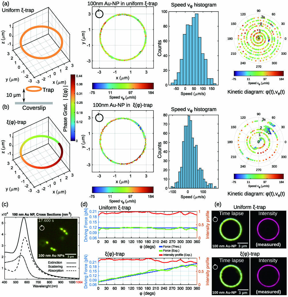
We investigate the optical transport of single and multiple metal NPs in several 3D traps operating at μ from the bottom coverslip glass (and μ from the top one), thus avoiding any interfering substrate effects. We start from the analysis of particle motion in a ring trap (radius μ and ) with two different phase-gradient profiles. The first case [see Fig. 1(a)] corresponds to the ring trap with phase-gradient strength , where the negative sign corresponds to clockwise rotation of the NP around the ring. The second example corresponds to a ring trap with linearly increasing phase-gradient strength and values ; see Fig. 1(b). The light power at the output aperture of the objective lens was , which corresponds to the intensity μ in the ring trap. The high-intensity gradients provide stable confinement of the NPs with positional radial stiffness of μ in both ring traps; see Appendix A.
Figure 1.(a) Ring trap (μ radius) with phase gradient strength induces clockwise NP (gold sphere of radius) transport motion around the ring. The next three plots in this row are used for NP motion analysis. The kinetic diagram represents the instantaneous tangential speed of the NP at the angular position . (b) The same as in (a) for ring trap with . The experimental results shown in (a) and (b) correspond to the NP motion observed in Visualization 1. (c) Cross sections of the considered gold NP; the inset dark-field image shows multiple gold NPs transported in the studied ring traps (Visualization 2); (d) predicted and estimated optical propulsion forces for each trap. The propulsion force has been estimated by using the measured intensity profile , red color plot (normalized intensity). (e) The time-lapse images (created from Visualization 1) coincide with the trapping beam’s shape (measured intensity) and confirm stable confinement and transport of the gold NP in the ring trap and trap.
Then we consider the transport of the NPs in a tilted ring trap where the optical propulsion force is able to move them evenly upstream, in the opposite direction to the trapping beam propagation. Finally, we show more sophisticated transport of NPs based on fast modification of the freestyle laser trap, using the example of a vibrating string trap.
A. Optical Transport of a Single Gold NP
Let us first study the motion of a single gold NP (); see Visualization 1. Its cross sections for extinction (), scattering (), and absorption () are displayed in Fig. 1(c) for a wavelength range between 400 nm and 1064 nm. The peak of at wavelength corresponds to the yellow color of the light scattered by the NP observed in Fig. 1(c) and Visualization 1. The extinction cross section at the trapping laser wavelength is , which is almost 70 times less than the maximum value of at the resonance wavelength. Such a relatively small value allows balancing the axial radiation and intensity-gradient forces providing the required all-optical confinement. Moreover, this value of the is still sufficient for NP propulsion along the ring trap due to the relatively large value of the intensity and transverse phase-gradient strength. The light absorption leads to a temperature increase of the NP [42], where is the thermal conductivity of water. We have observed that this temperature increase does not induce optothermal escape, enabling stable confinement and transport around the ring trap.
The estimated propulsion force profile, by using the measured intensity distribution and the predicted phase of the trapping beam, is almost constant, along the curve, as observed in Fig. 1(d). In Fig. 1(e), a time-lapse image of the NP motion and the measured intensity distribution of the ring trap clearly demonstrate the particle trajectory along the laser curve. The tracking of the NP position [see the second column of Fig. 1(a)] shows that the NP travels around the ring trap with a mean speed of μ, as observed in the corresponding speed histogram, which fits well to a Gaussian distribution with a standard deviation of 43 μm/s. The temporal evolution of the NP motion can be further analyzed using a kinetic diagram represented in polar coordinates, where the radial coordinate corresponds to time () and the polar angle corresponds to the angular position of the NP [see the fourth column of Fig. 1(a)]. The colored scale indicates the value of the instantaneous tangential speed . The kinetic diagram for the ring trap and the speed histogram, Fig. 1(a), indicate that the instantaneous speed of the NP fluctuates mostly due to random thermal force around the mean value according to the constant optical propulsion force.
In contrast, the ensemble averaged speed of the same gold NP changes during its transport around the ring trap. According to the prescribed phase-gradient strength , the propulsion force is [blue line plot in Fig. 1(d)], and therefore the NP speed should be . However, the intensity distribution of the experimental ring trap [see polar profile represented by the red line plot in Fig. 1(d)] is not completely constant, which leads to the force profile indicated by green color plot. The expected linear behavior of the speed is not exactly observed in the kinetic diagram displayed in Fig. 1(b). Specifically, the propulsion force decreased in the region and with respect to the theoretically predicted one. The minimum speed value is observed at , where the NP eventually swings back and forth in the azimuthal direction to the curve for a short time (maximum ) in some loops. We think that the thermal forces randomly acting upon the NP could be responsible for the motion fluctuations observed at . Residual (small) wavefront aberrations present in the trapping beam have not been completely compensated. They can cause a degradation of the optical confinement at and (see Appendix A) which is responsible for the deviation of the NP dynamics from the expected one in such locations of the ring trap. Note that the transported NP is more exposed to the randomly acting thermal forces in these regions than in the rest of the ring trap because of the diminished optical confinement, especially at . Thus, this fact explains the fluctuations of NP speed values measured at , as observed in the kinetic diagram for the ring () trap; see Fig. 1(b). However, qualitatively, the NP follows the expected speed regime: it reaches minimum and maximum values in the first and fourth quadrant, correspondingly, while the mean speed μ [see also the speed histogram in Fig. 1(b)] is close to the value obtained in the ring trap because the averaged propulsion force in both ring traps is similar.
B. Simultaneous Optical Transport of Multiple Metal NPs
The freestyle laser trap is well suited for optical transport of multiple particles, which is difficult to achieve by using a point-like trap. The dynamics of multiple gold NPs in the previously considered ring traps (see Visualization 2) is similar to what we have observed for the single NP. Their speed is almost constant in the ring trap, while it is notably changing in the ring trap, according to the optical propulsion force, while the electrodynamic interactions between metal NPs lead to plasmonic coupling. Indeed, we have observed a redshift change in the scattered illumination light due to the plasmonic coupling between two gold NPs forming a dimer. When these gold NPs are very close, the redshift falls in the infrared wavelength region, which cannot be observed with our color camera operating in the visible wavelength range.
In contrast, two silver NPs (e.g., radius ) can form a plasmonic dimer yielding a gradual redshift from blue to green [13], which we have studied by using the color camera. The corresponding cross sections for such silver NPs are displayed in Fig. 2(a). Since the resonance wavelength of a single silver NP is 433 nm, it strongly scatters blue light, as indicated in Fig. 2(a), while the cross sections at the trapping wavelength are and . A transported single silver NP experiences an estimated temperature increase of only , which is significantly less than for the considered gold NP.
Figure 2.(a) Calculated cross sections for a single silver NP ( radius) and for a dimer with interparticle distance and ; (b) measured dark-field images and time-lapse images illustrating the optical transport of the NPs around the considered ring traps (μ radius); see Visualization 3; (c) spectral response of the RGB camera along with the scattering cross sections for and . The corresponding predicted RGB color, shown in (d) for the case of a silver dimer with , is in good agreement with the experiment (measured RGB color) as displayed in the inset of (d).
The optical confinement and transport of the silver NPs are also stable in both types of ring traps (Visualization 3), as in the case of the previously considered gold NPs. Several frames of the recorded video (Visualization 3) are displayed in Fig. 2(b). In this experiment, the optical transport of multiple silver NPs starts with the ring trap (see the frames in the time interval ). During the first 2 s, the silver NPs travel as independent particles, and the scattered light used for NP visualization is blue (centered at 433 nm); see also the corresponding time-lapse image shown in Fig. 2(b). Due to the low value of (estimated propulsion force ), the measured mean speed of a single silver NP transported in the ring trap is μ. Nevertheless, as observed in Visualization 3 (for time ), the color of the scattered light exhibits a progressive redshifting due to the plasmonic coupling of the nearby silver NPs. Let us recall that the two nearby NPs, separated by a distance , form a homodimer, whose effective polarizability is given by Eq. (2). The calculated scattering cross section of this plasmonic dimer is shown in Fig. 2(a) for and . When the interparticle distance is , the resonance is shifted at the wavelength 460 nm and the corresponding dark-field image recorded by our camera shows a cyan color spot for this dimer. The spectral response of our 12-bit red–green–blue (RGB) camera (measured by the manufacturer) is shown in Fig. 2(c). Since the scattered light [proportional to ] collected by the camera is filtered according to its spectral response, it is possible to predict the RGB color image corresponding to the light scattered by the dimer, as shown in Fig. 2(d) for . According to this filtered light spectrum, the predicted cyan spot (RGB color code: 87, 189, 255) is similar to the one observed in the dark-field images [inset of Fig. 2(d)] associated with a silver NP dimer with . This procedure has been also applied to predict the color for dimers separated by distance , as observed in the inset image displayed in Fig. 2(a). Interestingly, two contacting silver NPs form a dimer (, with resonance wavelength at 493 nm) detected as a cyan–green spot (RGB color code: 104, 255, 205), also found in the dark-field images, as indicated in Fig. 2(b); see also Visualization 3 (e.g., for ). The measured mean speed of this dimer () is μ, which is 2.8 times faster than that of a single silver NP alone. This result is expected because such a dimer has , and therefore it experiences an optical propulsion force about 2.6 times stronger than the silver monomer. The confinement and transport of the dimers are also stable and fit well to the shape of the ring trap; see time-lapse image in Fig. 2(b). In the experiments, we have also observed optical transport of yellow and red light spots, probably corresponding to plasmonic trimers as reported in Ref. [11] (see Visualization 3). The silver NPs (both single NP and dimer) demonstrate a nonuniform motion driven by the optical propulsion force of the considered trap as expected; see Visualization 3 (e.g., ).
C. Transport of NPs in More Sophisticated Traps
In all the previous examples, the ring trap is contained in a plane transverse [e.g., ] to the trapping beam propagation. When the ring trap is tilted (e.g., by an angle ), its propulsion force is no longer constant because leads to a variable phase-gradient strength , as shown in Fig. 3(a). The silver NPs perform a downstream and upstream motion around the tilted ring trap; see Visualization 4 and Fig. 3(b). In this case, the NPs experience a maximum and minimum optical propulsion force at and , respectively. The NP cyclically travels (clockwise motion) around the tilted ring trap, reaching its maximum speed at in a downstream motion. In the angular position , the NP has a minimum speed value due to the weak propulsion force, as predicted by Eq. (4). The dark-field images displayed in Fig. 3(b) have been acquired by using the ETL focusing at the top and the bottom of tilted ring. Note that the phase gradient prescribed along the curve controls the direction of the local wave vector , which is normal to the light wavefronts, with one component in the propagation direction ( in our case) and the other component tangent to the curve. The radiation force associated with the first component is compensated for by the axial intensity-gradient force enabling stable trapping, whereas the force term associated with the tangential component [Eq. (4), optical propulsion force] can move the NP in both downstream and upstream (toward the light source) directions along the 3D curve. For example, in the case of a tilted ring, the phase gradient can be prescribed along it [see Fig. 3(a)] to move the confined particle upstream (pulling force action) and then downstream (pushing force action) in order to perform a clockwise rotation around the tilted ring, as observed in the experiment; see Fig. 3(b) and Visualization 4. Thus, the laser trap can work as a tractor beam that transports particles back to its source, opposite to the wave direction of propagation. The required retrograde (pulling) force arises when a particle scatters the wave’s momentum density downstream into the direction of propagation and then recoils upstream by conservation of momentum [43]. Up to now, this tractor beam behavior has been observed in the case of micrometer-sized dielectric particles; see, for example, Refs. [16,43,44]. Here, we have experimentally demonstrated that metal NPs can also be optically transported by a short-ranged tractor beam, described in the electric dipole approximation.
Figure 3.(a) Phase-gradient strength obtained when a ring trap (μ radius) is tilted by an angle ; (b) measured dark-field images and time-lapse image illustrating the optical transport of silver NPs ( radius) around the tilted ring trap (Visualization 4). The corresponding predicted and estimated optical propulsion forces are shown in (c). The maximum value of the phase-gradient force is obtained at ; its position is indicated by the arrow M in each case. (d) A trap in the form of a vibrating string can be created by using dynamic shape morphing. The experimental results shown in (e) correspond to the optical transport of the silver NPs in this vibrating string (first row); see Visualization 5. The second row displays the measured beam’s intensity of several optical traps comprising the vibrating string.
Let us recall that a freestyle laser trap can be easily shaped in any curve , even in the form of polygon comprising multiple corners [31]. To illustrate this fact, optical transport of silver NPs in a square trap is shown in the Appendix A as an example.
To study the 3D optical transport of multiple NPs around a more complex trap configuration, we finally considered the case of a trap whose shape is automatically changed to mimic a vibrating string (contained in the transverse plane), as sketched in Fig. 3(d). In this case, the silver NPs are simultaneously transported by the optical propulsion force and the intensity gradient force dragging the particles as the curve moves; see Visualization 5 and Fig. 3(e). This type of optical trap has been created by using a dynamic morphing technique reported in Ref. [28], where optical transport of dielectric particles (μ silica spheres) has been experimentally demonstrated.
Dynamic morphing allows programmable shape transformation of a 3D curved trap into a target shape (trajectory). Specifically, the particle trajectory is represented by using a set of linked Bézier splines that are easy and fast to compute [28]. In this example, we have used four Bézier splines linked by four knot points to create an initial shape in the form of a circle [Fig. 3(d)]. To obtain the vibrating string, the position of the knot points 1 and 3 can be shifted (e.g., randomly changed) while the position of the other knot points is fixed, as indicated in Fig. 3(e). In our case, the moving knot points describe a small circular trajectory (one clockwise and the other anticlockwise directions) in order to create the required curve shapes (strings). To create a smooth and progressive shape transformation between the initial and final string [extreme shapes shown in the last column of Fig. 3(e)] we have used 15 intermediate string shapes. The holograms encoding the corresponding polymorphic beams are precalculated (computation time of 5 s each; see Appendix A), and then they are displayed into the SLM at a frame rate of 25 Hz (switching time of 40 ms) to generate the optical traps working as a vibrating string. The considered example of optical trap (in the form of a vibrating string) demonstrates that the combination of both intensity-gradient and radiation forces allows achieving fast reconfigurable trajectories for all-optical transport of multiple NPs; see Visualization 5. An open string can be easily created just by removing one or several Bézier splines if needed. Dynamic morphing of the freestyle laser trap can also be applied for obstacle avoidance necessary in multiparticle transport operations such as programmable particle delivery [22,28,45]. The considered examples illustrate that 3D optical transport of plasmonic NPs is indeed possible, even in complex configurations.
4. CONCLUSIONS AND PERSPECTIVES
The presented results have fundamental and practical significance in the field of optical manipulation of nanostructures; this is particularly of interest in photonics, nanofabrication, sensing, etc. For the first time, 3D all-optical transport of Rayleigh metal NPs driven by a tailored phase-gradient force propelling the particles along target trajectories has been demonstrated. This has been achieved by using a freestyle laser trap, which is a structured single-beam trap in the form of a diffraction-limited arbitrary curve [16,28]. The transport of single and multiple noble metal NPs for different configurations of the curved traps and the optical propulsion force has been investigated. The 3D confinement of the NPs is stable, and their transport speed can be controlled along the target trajectory by using a constant or variable phase-gradient propulsion force on demand. It has been also shown that the trajectory’s shape and the propulsion force exerted on the NPs can be independently controlled, enabling programmable transport even in sophisticated optical trap configurations such as a tilted ring and a vibrating string. We expect that optical transport of multiple NPs in knot circuits or networks exhibiting multiple crossing points could be also possible, as has been experimentally demonstrated in Ref. [45] with the example of dielectric microspheres (μ silica spheres).
In previous studies, it has been pointed out the importance of a transverse phase-gradient force to induce electrodynamic interactions [18,19,21] between metal NPs such as tunable optical binding (e.g., useful for assembly of NPs and optical matter control) [21] as well as plasmonic coupling (e.g., useful in biosensing and nanophotonics) when they approach each other. Such electrodynamic interactions have been previously investigated by using a vortex trap settled in contact with the chamber wall to achieve axial NPs confinement. Here, we have used a freestyle laser trap that allows studying these as well as other particle interactions far away from all the chamber walls, thus avoiding their interfering effects. In particular, we have observed plasmonic coupling of silver NPs (forming dimers) induced by the propulsion phase-gradient force around the optical trap. The experimental results show a tunable color-change dynamics in the scattered light due to plasmonic coupling, as expected [10,12,13]. The electrodynamic interaction between two proximal NPs is responsible for their plasmonic coupling and dimer formation. The transport of two NPs with different velocities is in favor of their encounters and therefore of the dimer formation. When one-directional phase gradient is used, as in the studied ring trap, the dimer formation is more probable in the regions of low propulsion force where stochastic NP motion is dominant. Alternatively, the curved laser trap can be designed with phase gradients oriented in opposite directions in a localized region of interest [31], thereby increasing the encounter of the transported NPs. Thus, the proper design of the phase gradient of the trapping beam allows controlling the dimer formation in a certain location.
While these experiments have been conducted with metal nanospheres, the results can be applicable to other nanostructures. Plasmonic NPs and nanostructures are of high interest in optics and photonics technologies. We envision a further development of nanophotonics applications based on the reported achievements.
APPENDIX A
Experimental Setup
Our experimental setup, sketched in Fig.?4, consists of an inverted dark-field microscope, a programmable reflective phase-only SLM (Meadowlark Optics, HSP1920-600-1300-HSP8, LCOS, 8-bit phase level, pixel size of 9.2?μm), and a high-speed color CMOS camera (Thorlabs CS505CU, 12-bit level, pixel size of 3.45?μm). To generate the trapping beam, a phase-only hologram addressed onto the SLM modulates an input-collimated CW laser beam (Azurlight Systems, ALS-IR-1064-10-I-CP-SF, , maximum optical power of 10?W, power stability , pointing stability μ, linear-polarized), which is then projected [with a Keplerian telescope comprising two relay lenses (RLs)] into the input back aperture of the microscope objective lens (Nikon CFI Plan Apochromat Lambda , 1.45 NA, oil immersion). The trapping beam is circularly polarized by using a quarter-wave plate (QWP in Fig.?4). The RLs and the tube lens of the microscope have a focal length of 200?mm; see Fig.?4. Note that the dark-field diaphragm (required for dark-field imaging of the NPs) has been mounted in this imaging system placed outside the microscope Fig.?4 instead of mounting it in the back aperture of the objective lens, thereby preventing the cutoff of the projected trapping beam.
Figure 4.Sketch of the experimental setup used for 3D all-optical transport of NPs. The inverted dark-field microscope (comprising the condenser and objective lenses) has incorporated into two systems: the measurement setup required for visualization and position tracking of the NPs as well as the setup for shaping the laser traps (SLM and the laser device). The laser beam modulated by the SLM is relayed onto the back aperture of the objective lens by using a set of two identical convergent lenses (focal length of 200 mm) working as a Keplerian telescope. Both the microscope’s tube lens (with focal length ) and the RL () are achromatic convergent lenses. The ETL (placed at from the camera) allows for optical scanning of the sample [41].
Figure 5.Result of pmrf calculated from measured NP positions. This corresponds to an effective radial trapping potential experienced by a single gold NP in the ring uniform (a) trap and (b) trap. The black arrows indicate the regions (at and ) of diminished radial trapping potential in the trap.
Figure 6.(a) Optical transport of silver NPs in a square trap; see Visualization 6; (b) time-lapse images of the NPs motion during 10 and 6 s, respectively. The pink color observed in the first time-lapse image indicates the presence of a trimer [red color spot in image (a), at time 0.76 s] confined for a time of 4 s; then it escapes from the trap due to strong absorption of light (of the laser trapping beam). The shape of the time-lapse images coincides with the trapping beam’s intensity distribution shown in (b), as expected.
José A. Rodrigo, Mercedes Angulo, Tatiana Alieva, "All-optical motion control of metal nanoparticles powered by propulsion forces tailored in 3D trajectories," Photonics Res. 9, 1 (2021)