• Opto-Electronic Advances
  • Vol. 3, Issue 2, 190024-1 (2020)
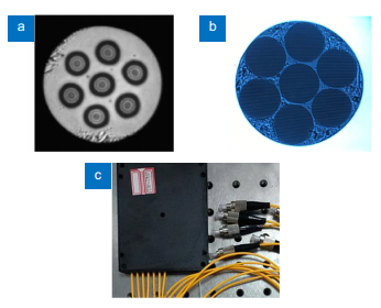
Zhiyong Zhao1, Ming Tang2、*, and Chao Lu1
Author Affiliations
  • 1Photonics Research Centre, Department of Electronic and Information Engineering, The Hong Kong Polytechnic University, Kowloon, Hong Kong
  • 2National Engineering Laboratory of Next Generation Internet Access Networks, School of Optical and Electronic Infor-mation, Huazhong University of Science and Technology, Wuhan 430074, China
  • show less
    DOI: 10.29026/oea.2020.190024 Cite this Article
    Zhiyong Zhao, Ming Tang, Chao Lu. Distributed multicore fiber sensors[J]. Opto-Electronic Advances, 2020, 3(2): 190024-1 Copy Citation Text show less
    (a) Cross-sectional view of the fabricated 7-core fiber. (b) Endview of the 7-SMF bundle. (c) The packaged MCF fan-in/out coupler. Figure reproduced from ref.22, Optical Society of America.
    Fig. 1. (a) Cross-sectional view of the fabricated 7-core fiber. (b) Endview of the 7-SMF bundle. (c) The packaged MCF fan-in/out coupler. Figure reproduced from ref.22, Optical Society of America.
    Schematic diagram of the bent MCF with a bending radius of R. Core A and Core B represent the elongated outer side core and the compressed inner side core, respectively.Figure reproduced from ref.24, Optical Society of America.
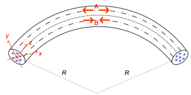
    Fig. 2. Schematic diagram of the bent MCF with a bending radius of R. Core A and Core B represent the elongated outer side core and the compressed inner side core, respectively.Figure reproduced from ref.24, Optical Society of America.
    The transversal spatial distribution of cores of a seven-core fiber, showing the definitions of some important geometrical parameters.Figure reproduced from ref.25, Optical Society of America.
    Fig. 3. The transversal spatial distribution of cores of a seven-core fiber, showing the definitions of some important geometrical parameters.Figure reproduced from ref.25, Optical Society of America.
    An example of multicore fiber-based shape measurement. Figure reproduced from ref.26, Optical Society of America.
    Fig. 4. An example of multicore fiber-based shape measurement. Figure reproduced from ref.26, Optical Society of America.
    Strain measurements in a multicore fiber by using co-located fiber Bragg grating arrays for shape sensing.
    Fig. 5. Strain measurements in a multicore fiber by using co-located fiber Bragg grating arrays for shape sensing.
    Illustration of shape sensing using helical multicore optical fiber.(a) Microscope view of the four-core sensing fiber, sensing triad in red. (b) Illustration of helical cores along length of fiber. Figure reproduced from ref.40, SPIE.
    Fig. 6. Illustration of shape sensing using helical multicore optical fiber.(a) Microscope view of the four-core sensing fiber, sensing triad in red. (b) Illustration of helical cores along length of fiber. Figure reproduced from ref.40, SPIE.
    (a) Reel-to-reel array inscription apparatus allowing continuous fabrication of gratings in all cores through UV transparent coating. (b) End-view image of a seven-core fiber with coating removed.(c) Twisted multicore fiber schematic showing UV transparent coating (right). Bare glass region (left) shown to highlight twisted multicore continuous gratings. Figure reproduced from ref.44, IEEE.
    Fig. 7. (a) Reel-to-reel array inscription apparatus allowing continuous fabrication of gratings in all cores through UV transparent coating. (b) End-view image of a seven-core fiber with coating removed. (c) Twisted multicore fiber schematic showing UV transparent coating (right). Bare glass region (left) shown to highlight twisted multicore continuous gratings. Figure reproduced from ref.44, IEEE.
    Top view of the Brillouin gain pectrum in an off-center core of the MCF showing bound random BFS variations resulting from bending due to fiber coiling. Figure reproduced from ref.46, IEEE.
    Fig. 8. Top view of the Brillouin gain pectrum in an off-center core of the MCF showing bound random BFS variations resulting from bending due to fiber coiling. Figure reproduced from ref.46, IEEE.
    (a) Extracted Brillouin frequency shift for different bending radii. (b) Dependence of BFS on curvature measured along an outer core of the MCF. The error intervals on the curvature and the measured BFS are marked in green and purple triangle dots, respectively. Figure reproduced from ref.25, Optical Society of America.
    Fig. 9. (a) Extracted Brillouin frequency shift for different bending radii. (b) Dependence of BFS on curvature measured along an outer core of the MCF. The error intervals on the curvature and the measured BFS are marked in green and purple triangle dots, respectively. Figure reproduced from ref.25, Optical Society of America.
    (a) Three O-shapes made for validating the ability of distributed curvature and shape sensing based on BOTDA in MCF. (b) The measured BFS profiles as a function of distance along three cores around the 3 O-shape regions. (c) Retrieved bending angle for the 3 O-shape regions. (d) Retrieved curvature for the 3 O-shape regions. Figure reproduced from ref.25, Optical Society of America.
    Fig. 10. (a) Three O-shapes made for validating the ability of distributed curvature and shape sensing based on BOTDA in MCF. (b) The measured BFS profiles as a function of distance along three cores around the 3 O-shape regions. (c) Retrieved bending angle for the 3 O-shape regions. (d) Retrieved curvature for the 3 O-shape regions. Figure reproduced from ref.25, Optical Society of America.
    Experimental setup of the MCF based SDM ROTDR and BOTDR hybrid system. LD: Laser diode; PC: polarization controller; SOA: semiconductor optical amplifier; MZM: Mach-Zehnder modulator; EDFA: erbium-doped fiber amplifier; PS: polarization switch; BPF: bandpass filter; BPD: balanced photodetector; Att.: tunable attenuator; APD: avalanche photodiode; ESA: electrical spectrum analyzer; OSc.: oscilloscope; the inset shows the cross-section view of the used MCF in the experiment. Figure reproduced from ref.53, Optical Society of America.
    Fig. 11. Experimental setup of the MCF based SDM ROTDR and BOTDR hybrid system. LD: Laser diode; PC: polarization controller; SOA: semiconductor optical amplifier; MZM: Mach-Zehnder modulator; EDFA: erbium-doped fiber amplifier; PS: polarization switch; BPF: bandpass filter; BPD: balanced photodetector; Att.: tunable attenuator; APD: avalanche photodiode; ESA: electrical spectrum analyzer; OSc.: oscilloscope; the inset shows the cross-section view of the used MCF in the experiment. Figure reproduced from ref.53, Optical Society of America.
    (a) Cross-sectional view of the heterogeneous MCF, whose outer six cores are made from the same preform but the central core is made from another preform. (b) Relative index profile of the heterogeneous MCF. Figure reproduced from ref.56, Optical Society of America.
    Fig. 12. (a) Cross-sectional view of the heterogeneous MCF, whose outer six cores are made from the same preform but the central core is made from another preform. (b) Relative index profile of the heterogeneous MCF. Figure reproduced from ref.56, Optical Society of America.
    The measured BGS of a heterogeneous MCF. (a) The central core with peak at ~10.81 GHz. (b) The outer core with peak at ~10.74 GHz. Figure reproduced from ref.56, Optical Society of America.
    Fig. 13. The measured BGS of a heterogeneous MCF. (a) The central core with peak at ~10.81 GHz. (b) The outer core with peak at ~10.74 GHz. Figure reproduced from ref.56, Optical Society of America.
    The measured BFS of two symmetrical outer cores when the MCF was spooled with random orientations; the green trace is the averaged BFS of two symmetrical outer cores. Figure reproduced from ref.56, Optical Society of America.
    Fig. 14. The measured BFS of two symmetrical outer cores when the MCF was spooled with random orientations; the green trace is the averaged BFS of two symmetrical outer cores. Figure reproduced from ref.56, Optical Society of America.
    Experimental setup of the MCF SDM ROTDR and φ-OTDR hybrid sensor. LD: Laser diode; PC: polarization controller; SOA: semiconductor optical amplifier; PG: pulse generator; EDFA: erbium-doped fiber amplifier; BPF: band-pass filter; OC: optical coupler; Att.: tunable attenuator; APD: avalanche photodiode; PD: photodetector; OSc.: oscilloscope; the inset shows the cross sectional view of the seven-core MCF. Figure reproduced from ref.61, IEEE.
    Fig. 15. Experimental setup of the MCF SDM ROTDR and φ-OTDR hybrid sensor. LD: Laser diode; PC: polarization controller; SOA: semiconductor optical amplifier; PG: pulse generator; EDFA: erbium-doped fiber amplifier; BPF: band-pass filter; OC: optical coupler; Att.: tunable attenuator; APD: avalanche photodiode; PD: photodetector; OSc.: oscilloscope; the inset shows the cross sectional view of the seven-core MCF. Figure reproduced from ref.61, IEEE.
    Experimental setup for the SDM reflectometer and interferometer hybrid sensor. LD: Laser diode; OC: optical coupler; PC: polarization controller; Att.: tunable attenuator; EOM: electro-optic modulator; PG: pulse generator; EDFA: erbium-doped fiber amplifier; BPF: band-pass filter; PD: photodetector; OSc.: oscilloscope. Figure reproduced from ref.63, IEEE.
    Fig. 16. Experimental setup for the SDM reflectometer and interferometer hybrid sensor. LD: Laser diode; OC: optical coupler; PC: polarization controller; Att.: tunable attenuator; EOM: electro-optic modulator; PG: pulse generator; EDFA: erbium-doped fiber amplifier; BPF: band-pass filter; PD: photodetector; OSc.: oscilloscope. Figure reproduced from ref.63, IEEE.
    Experimental setup of the MCF based SDM hybrid BOTDA and φ-OTDR sensing system. LD: Laser diode; PC: polarization controller; SOA: semiconductor optical amplifier; MZM: Mach-Zehnder modulator; EDFA: erbium-doped fiber amplifier; PS: polarization switch; Att.: attenuator; PD: photodetector; Fan-in: fan-in coupler; Fan-out: fan-out coupler. Figure reproduced from ref.67, Optical Society of America.
    Fig. 17. Experimental setup of the MCF based SDM hybrid BOTDA and φ-OTDR sensing system. LD: Laser diode; PC: polarization controller; SOA: semiconductor optical amplifier; MZM: Mach-Zehnder modulator; EDFA: erbium-doped fiber amplifier; PS: polarization switch; Att.: attenuator; PD: photodetector; Fan-in: fan-in coupler; Fan-out: fan-out coupler. Figure reproduced from ref.67, Optical Society of America.
    Zhiyong Zhao, Ming Tang, Chao Lu. Distributed multicore fiber sensors[J]. Opto-Electronic Advances, 2020, 3(2): 190024-1
    Download Citation